EP0871232A1 - Wiederaufladbare Lithium-Ionen-Zelle - Google Patents
Wiederaufladbare Lithium-Ionen-Zelle Download PDFInfo
- Publication number
- EP0871232A1 EP0871232A1 EP98102315A EP98102315A EP0871232A1 EP 0871232 A1 EP0871232 A1 EP 0871232A1 EP 98102315 A EP98102315 A EP 98102315A EP 98102315 A EP98102315 A EP 98102315A EP 0871232 A1 EP0871232 A1 EP 0871232A1
- Authority
- EP
- European Patent Office
- Prior art keywords
- cell
- electrode
- electrolyte
- cover
- electrode plates
- Prior art date
- Legal status (The legal status is an assumption and is not a legal conclusion. Google has not performed a legal analysis and makes no representation as to the accuracy of the status listed.)
- Granted
Links
Images

Classifications
-
- H—ELECTRICITY
- H01—ELECTRIC ELEMENTS
- H01M—PROCESSES OR MEANS, e.g. BATTERIES, FOR THE DIRECT CONVERSION OF CHEMICAL ENERGY INTO ELECTRICAL ENERGY
- H01M10/00—Secondary cells; Manufacture thereof
- H01M10/04—Construction or manufacture in general
- H01M10/0413—Large-sized flat cells or batteries for motive or stationary systems with plate-like electrodes
-
- H—ELECTRICITY
- H01—ELECTRIC ELEMENTS
- H01M—PROCESSES OR MEANS, e.g. BATTERIES, FOR THE DIRECT CONVERSION OF CHEMICAL ENERGY INTO ELECTRICAL ENERGY
- H01M50/00—Constructional details or processes of manufacture of the non-active parts of electrochemical cells other than fuel cells, e.g. hybrid cells
- H01M50/10—Primary casings, jackets or wrappings of a single cell or a single battery
- H01M50/102—Primary casings, jackets or wrappings of a single cell or a single battery characterised by their shape or physical structure
- H01M50/103—Primary casings, jackets or wrappings of a single cell or a single battery characterised by their shape or physical structure prismatic or rectangular
-
- H—ELECTRICITY
- H01—ELECTRIC ELEMENTS
- H01M—PROCESSES OR MEANS, e.g. BATTERIES, FOR THE DIRECT CONVERSION OF CHEMICAL ENERGY INTO ELECTRICAL ENERGY
- H01M50/00—Constructional details or processes of manufacture of the non-active parts of electrochemical cells other than fuel cells, e.g. hybrid cells
- H01M50/10—Primary casings, jackets or wrappings of a single cell or a single battery
- H01M50/116—Primary casings, jackets or wrappings of a single cell or a single battery characterised by the material
- H01M50/117—Inorganic material
- H01M50/119—Metals
-
- H—ELECTRICITY
- H01—ELECTRIC ELEMENTS
- H01M—PROCESSES OR MEANS, e.g. BATTERIES, FOR THE DIRECT CONVERSION OF CHEMICAL ENERGY INTO ELECTRICAL ENERGY
- H01M50/00—Constructional details or processes of manufacture of the non-active parts of electrochemical cells other than fuel cells, e.g. hybrid cells
- H01M50/10—Primary casings, jackets or wrappings of a single cell or a single battery
- H01M50/116—Primary casings, jackets or wrappings of a single cell or a single battery characterised by the material
- H01M50/124—Primary casings, jackets or wrappings of a single cell or a single battery characterised by the material having a layered structure
-
- H—ELECTRICITY
- H01—ELECTRIC ELEMENTS
- H01M—PROCESSES OR MEANS, e.g. BATTERIES, FOR THE DIRECT CONVERSION OF CHEMICAL ENERGY INTO ELECTRICAL ENERGY
- H01M50/00—Constructional details or processes of manufacture of the non-active parts of electrochemical cells other than fuel cells, e.g. hybrid cells
- H01M50/10—Primary casings, jackets or wrappings of a single cell or a single battery
- H01M50/172—Arrangements of electric connectors penetrating the casing
- H01M50/174—Arrangements of electric connectors penetrating the casing adapted for the shape of the cells
- H01M50/176—Arrangements of electric connectors penetrating the casing adapted for the shape of the cells for prismatic or rectangular cells
-
- H—ELECTRICITY
- H01—ELECTRIC ELEMENTS
- H01M—PROCESSES OR MEANS, e.g. BATTERIES, FOR THE DIRECT CONVERSION OF CHEMICAL ENERGY INTO ELECTRICAL ENERGY
- H01M50/00—Constructional details or processes of manufacture of the non-active parts of electrochemical cells other than fuel cells, e.g. hybrid cells
- H01M50/30—Arrangements for facilitating escape of gases
- H01M50/342—Non-re-sealable arrangements
- H01M50/3425—Non-re-sealable arrangements in the form of rupturable membranes or weakened parts, e.g. pierced with the aid of a sharp member
-
- H—ELECTRICITY
- H01—ELECTRIC ELEMENTS
- H01M—PROCESSES OR MEANS, e.g. BATTERIES, FOR THE DIRECT CONVERSION OF CHEMICAL ENERGY INTO ELECTRICAL ENERGY
- H01M50/00—Constructional details or processes of manufacture of the non-active parts of electrochemical cells other than fuel cells, e.g. hybrid cells
- H01M50/50—Current conducting connections for cells or batteries
- H01M50/543—Terminals
- H01M50/547—Terminals characterised by the disposition of the terminals on the cells
- H01M50/55—Terminals characterised by the disposition of the terminals on the cells on the same side of the cell
-
- H—ELECTRICITY
- H01—ELECTRIC ELEMENTS
- H01M—PROCESSES OR MEANS, e.g. BATTERIES, FOR THE DIRECT CONVERSION OF CHEMICAL ENERGY INTO ELECTRICAL ENERGY
- H01M50/00—Constructional details or processes of manufacture of the non-active parts of electrochemical cells other than fuel cells, e.g. hybrid cells
- H01M50/50—Current conducting connections for cells or batteries
- H01M50/543—Terminals
- H01M50/552—Terminals characterised by their shape
- H01M50/553—Terminals adapted for prismatic, pouch or rectangular cells
-
- H—ELECTRICITY
- H01—ELECTRIC ELEMENTS
- H01M—PROCESSES OR MEANS, e.g. BATTERIES, FOR THE DIRECT CONVERSION OF CHEMICAL ENERGY INTO ELECTRICAL ENERGY
- H01M50/00—Constructional details or processes of manufacture of the non-active parts of electrochemical cells other than fuel cells, e.g. hybrid cells
- H01M50/50—Current conducting connections for cells or batteries
- H01M50/572—Means for preventing undesired use or discharge
- H01M50/584—Means for preventing undesired use or discharge for preventing incorrect connections inside or outside the batteries
- H01M50/586—Means for preventing undesired use or discharge for preventing incorrect connections inside or outside the batteries inside the batteries, e.g. incorrect connections of electrodes
-
- H—ELECTRICITY
- H01—ELECTRIC ELEMENTS
- H01M—PROCESSES OR MEANS, e.g. BATTERIES, FOR THE DIRECT CONVERSION OF CHEMICAL ENERGY INTO ELECTRICAL ENERGY
- H01M50/00—Constructional details or processes of manufacture of the non-active parts of electrochemical cells other than fuel cells, e.g. hybrid cells
- H01M50/50—Current conducting connections for cells or batteries
- H01M50/572—Means for preventing undesired use or discharge
- H01M50/584—Means for preventing undesired use or discharge for preventing incorrect connections inside or outside the batteries
- H01M50/59—Means for preventing undesired use or discharge for preventing incorrect connections inside or outside the batteries characterised by the protection means
- H01M50/593—Spacers; Insulating plates
-
- H—ELECTRICITY
- H01—ELECTRIC ELEMENTS
- H01M—PROCESSES OR MEANS, e.g. BATTERIES, FOR THE DIRECT CONVERSION OF CHEMICAL ENERGY INTO ELECTRICAL ENERGY
- H01M10/00—Secondary cells; Manufacture thereof
- H01M10/05—Accumulators with non-aqueous electrolyte
- H01M10/052—Li-accumulators
- H01M10/0525—Rocking-chair batteries, i.e. batteries with lithium insertion or intercalation in both electrodes; Lithium-ion batteries
-
- Y—GENERAL TAGGING OF NEW TECHNOLOGICAL DEVELOPMENTS; GENERAL TAGGING OF CROSS-SECTIONAL TECHNOLOGIES SPANNING OVER SEVERAL SECTIONS OF THE IPC; TECHNICAL SUBJECTS COVERED BY FORMER USPC CROSS-REFERENCE ART COLLECTIONS [XRACs] AND DIGESTS
- Y02—TECHNOLOGIES OR APPLICATIONS FOR MITIGATION OR ADAPTATION AGAINST CLIMATE CHANGE
- Y02E—REDUCTION OF GREENHOUSE GAS [GHG] EMISSIONS, RELATED TO ENERGY GENERATION, TRANSMISSION OR DISTRIBUTION
- Y02E60/00—Enabling technologies; Technologies with a potential or indirect contribution to GHG emissions mitigation
- Y02E60/10—Energy storage using batteries
-
- Y—GENERAL TAGGING OF NEW TECHNOLOGICAL DEVELOPMENTS; GENERAL TAGGING OF CROSS-SECTIONAL TECHNOLOGIES SPANNING OVER SEVERAL SECTIONS OF THE IPC; TECHNICAL SUBJECTS COVERED BY FORMER USPC CROSS-REFERENCE ART COLLECTIONS [XRACs] AND DIGESTS
- Y02—TECHNOLOGIES OR APPLICATIONS FOR MITIGATION OR ADAPTATION AGAINST CLIMATE CHANGE
- Y02P—CLIMATE CHANGE MITIGATION TECHNOLOGIES IN THE PRODUCTION OR PROCESSING OF GOODS
- Y02P70/00—Climate change mitigation technologies in the production process for final industrial or consumer products
- Y02P70/50—Manufacturing or production processes characterised by the final manufactured product
Definitions
- the invention relates to a rechargeable lithium-ion cell.
- Rechargeable lithium-ion cells especially cells that have energy levels of 20 Can store up to 100 Ah require safety devices and a constructive one Designing the cell to prevent the cells from losing electrolyte, penetrating Water and / or electrical insulation problems may be damaged. Also the Cell heating due to high internal resistance when exposed to high loads Streaming is problematic. There are a number of rechargeable lithium-ion cells known that one or the other of the problems mentioned in the operation of the cells should decrease. Especially when using high-capacity cells to build However, battery modules for the use of electric road vehicles are the requirements the safety and reliability of the lithium-ion cells used high.
- the object of the invention is to provide rechargeable lithium-ion cells, that meet the special requirements in battery modules of electric road vehicles satisfy.
- the entirety of the constructive features of the lithium-ion cell according to the invention carries the special requirements regarding safety and mechanical Loads on cells when used in electric road vehicles. So is due pressure stability and security against mechanical destruction of the cells a stainless steel cell housing is preferred. Since metallic cell housings are conductive, the cell housing is often used as an electrode pole. However, this also increases Danger of a short circuit, because a slight contact of the counter electrode with the Cell wall is sufficient for short-circuiting. According to the invention, the inner and external insulation of the cell housing produces a high short-circuit protection.
- the This encloses, nested, electrolyte-resistant electrodes Half shells made of a non-conductive material, such as polyvinylidene difluoride (PVdF) electrically isolated from the housing walls.
- PVdF polyvinylidene difluoride
- a protective lacquer coating ensures or an insulating shrink tube film that is up to 10 mm below the upper edge of the Reach the cell vessel and a cover that is placed over the lid of the cell Insulation material such as polyethylene terephthalate (PET) for the external insulation of the invention Cell.
- the positive electrode pole made of titanium or aluminum-coated Copper and the negative electrode pole made of copper. So that is ensures a very good electrochemical resistance of the lithium-ion cell and on the other hand the electrical resistance is kept low. Advantageously thus the heating of the cell and thus the irreversible at high current loads Reduced energy consumption.
- the positive current conductors are ultrasonically welded with a Connected aluminum rivet and this by riveting, especially wobble riveting connected to the positive electrode pole.
- the copper arrester flags of the negative Electrode plates are welded with a copper rivet and to the negative electrode pole riveted.
- the proposed connection of the electrode plates with the Electrode poles leads on the one hand to the removal of the resistance-increasing oxide layers, on the other hand by one that does not damage the surface of the electrode poles Connection to a cell that can withstand currents of 10 to 300 amperes. i.e. against the vibrations occurring in vehicle operation, is stable.
- the rechargeable lithium-ion cells according to the invention are thereby furthermore characterized that it is above the electrolyte level of the cells in their normal position Own bursting membrane. In the event of damage to the bursting membrane occurs solely through the Gravity no electrolyte.
- the electrode poles are advantageously designed as ceramic metal bushings.
- the prefabricated feed-through elements are made of VA material with their welding collar welded to the collar drawn into the cell cover from the same material.
- the electrode plates are encased with the insulating half-shells and in the cell housing inserted.
- the cells are actually closed, for example thanks to the laser welding of the lid and cell container. It becomes hermetic tightly sealed cell in which the lifetime-reducing penetration of water is avoided.
- the proposed cell and the method allows to simplify assembly, cost-effective manufacture by reducing the number of components required and increasing the safety of the Cells and their manufacture.
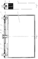
- Figures 1 and 2 show sectional views of the cell 1 according to the invention the electrode poles 3, a bursting membrane 4 and the filling dome 5 are integrated in the cover 2.
- An anti-twist protection 6, the passages 10, extends over the inside of the cover 2. 11 to the bursting membrane 4 and to the filling dome 5.
- At the electrode poles 3 are Current collector tabs 7 of the electrode plates 8 fastened with rivets 9, the rivets 9 with the current conductor tabs 7 are connected by means of ultrasonic welding.
- the Current collector tabs 7 of the positive electrode plates 8 are preferably made of aluminum and are welded with an aluminum rivet 9 and by wobble riveting the positive electrode pole 3 coated with approx. 50 ⁇ m pure aluminum.
- the Current conductor tabs 7 of the negative electrode plates 8 preferably consist of Copper and are welded to a copper rivet 9 and to the negative electrode pole 3 riveted.
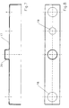
- Figures 3 and 4 show the sectional view and the top view of the anti-rotation device 6.
- the anti-rotation device 6 has passages 10, 11 to the bursting membrane 4 and the filling dome 5.
- the passages 10 to the bursting membrane 4 are arranged symmetrically to the section axis A - A. As a result, the assembly becomes a bursting membrane 4 in terms of orientation simplified.
- narrow cells 1, i.e. for cells 1, the electrode poles 3 of which are relatively dense stand together the passages 10 are omitted and the bursting membrane 4 in the Filling dome 5 welded in.
- the bursting membrane 4 is then only according to the invention filling cell 1 with electrolyte and after the subsequent commissioning cycles introduced into the bursting membrane dome 5.
- the anti-rotation device 6 also has a reinforced one Area 12 which is above the connection area of the current conductor tabs 7 extends to the electrode plates 8.
- the area 12 is reinforced with ribs 13 and becomes too the current collector tabs 7 lowered.
- the anti-rotation device 6 also has a between the current collector tabs 7 of the different polarities reaching section 14, the position of the Electrode plates 8 centered to each other, the filling with electrolyte allowed and the risk of short circuit reduced in the area of the current collector tabs 7.
- the cuts A - A, B - B and C - C show the respective designs of the anti-rotation cross section.
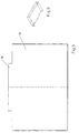
- Figures 5 and 6 show the half-shells 15, which are made of an electrolyte-resistant, electrically non-conductive material are made.
- the half shells 15 made of polyvinylidene difluoride or a copolymer with hexafluoropropylene.
- the half-shells 15 are nested one inside the other so that they enclose the electrode packet.
- the area of the connection of the current conductor tabs 7 is identified with the tab 16 to the electrode plates 8 protected from contact with the cell housing 21. Even when the separator is chafed through, the electrode plates 8 are through the half-shells 15 protected against contact with the cell housing 21.
- the electrical insulation of the cell 1 serves in addition to the anti-rotation 6 and the half-shells 15 protection formed inside the cell 1, an external electrical insulation of the Cell housing 21.
- the cell housing 21 is up to about 10 mm below the top Edge of the cell vessel 21 isolated with a protective lacquer coating.
- the cover 17 shown in Figures 7 and 8 is slipped.
- the cover hood 17 has openings 18, 19 for the electrode poles 3 and for the bursting membrane 4.
- the filling dome 5 is covered by the dome 20 of the cover 17. With those already mentioned narrow cells, in which the bursting membrane 4 is integrated into the filling dome 5 is accordingly the opening 19 in the dome 20 of the cover 17 is provided.
Abstract
Description
Claims (7)
- Wiederaufladbare Lithium-Ionen-Zelle prismatischer Gestalt mit einer Vielzahl von Elektrodenplatten, dadurch gekennzeichnet, daß die Zelle (1)a) ein metallisches Gehäuse (21) besitzt, welches innen durch zwei die Elektrodenplatten (8) und die Stromableiterfahnen (7) überdeckende Halbschalen (15) aus einem nichtleitenden Werkstoff und außen durch einen Isolationsüberzug elektrisch isoliert ist,b) eine Berstmembran (4) besitzt, welche sich über dem Elektrolytspiegel der Zelle (1) in ihrer Normallage befindet undc) einen sich über die gesamte Fläche des Deckels (2) erstreckenden Verdrehschutz (6) besitzt, welcher zusätzlich Zentrier- und Montagefunktionen für das aus den Elektrodenplatten (8) bestehende Elektrodenpaket aufweist.
- Zelle nach Anspruch 1, dadurch gekennzeichnet, daß die elektrische Isolation im Inneren Zelle (1) aus zwei ineinander geschachtelten Halbschalen (15) und dem Verdrehschutz (6) besteht, wobei der Verdrehschutz (6) zum Deckel hin Durchgänge (10,11) zur Berstmembran (4) und zum Befülldom (5) besitzt und die Zelle außen mit einem Schutzlacküberzug sowie einer Abdeckhaube (17) versehen ist.
- Zelle nach Anspruch 1, dadurch gekennzeichnet, daß die Elektrodenpole (3) aus Kupfer bestehen, wobei der positive Elektrodenpol (3) im Inneren der Zelle (1) mit Reinaluminium beschichtet ist.
- Zelle nach Anspruch 3, dadurch gekennzeichnet, daß die Elektrodenpole (3) durch eine Keramikmetalldurchführung elektrolytdicht mit dem Zellengehäuse verbunden sind.
- Verfahren zur Herstellung einer wiederaufladbaren Lithium-Ionen-Zelle gemäß Anspruch 1, dadurch gekennzeichnet, daßa) die Stromableiterfahnen (7) der positiven Elektrodenplatten (8) mit einem Aluminiumniet (9) verschweißt und an den positiven Elektrodenpol (3) und die Stromableiterfahnen (7) der negativen Elektrodenplatten (8) mit einem Kupferniet (9) verschweißt und an den negativen Elektrodenpol (3) angenietet werden,b) das aus den Elektrodenplatten (8) bestehende Elektrodenpaket mit den Halbschalen (15) umhüllt und in das Zellengefäß (21) eingeschoben,c) der Deckel (2) mit dem Zellengefäß (21) verschweißt,d) die Zelle (1) über den Befülldom (5) mit Elektrolyt befüllt und durch Zyklisieren in Betrieb gesetzt unde) der Befülldom (5) nach Inbetriebnahme der Zelle (1) elektrolytdicht verschlossen wird.
- Verfahren nach Anspruch 5, dadurch gekennzeichnet, daß der elektrolytdichte Verschluß der Zelle (1) mittels Laserverschweißung vorgenommen wird.
- Verwendung einer wiederaufladbaren Lithium-Ionen-Zelle gemäß einem oder mehreren der Ansprüche 1 bis 6 als Bordnetzbatterie für Kraftfahrzeuge.
Applications Claiming Priority (2)
| Application Number | Priority Date | Filing Date | Title |
|---|---|---|---|
| DE19714846 | 1997-04-10 | ||
| DE19714846A DE19714846A1 (de) | 1997-04-10 | 1997-04-10 | Wiederaufladbare Lithium-Ionen-Zelle |
Publications (2)
| Publication Number | Publication Date |
|---|---|
| EP0871232A1 true EP0871232A1 (de) | 1998-10-14 |
| EP0871232B1 EP0871232B1 (de) | 2000-12-06 |
Family
ID=7826035
Family Applications (1)
| Application Number | Title | Priority Date | Filing Date |
|---|---|---|---|
| EP98102315A Expired - Lifetime EP0871232B1 (de) | 1997-04-10 | 1998-02-11 | Wiederaufladbare Lithium-Ionen-Zelle |
Country Status (4)
| Country | Link |
|---|---|
| US (1) | US6007944A (de) |
| EP (1) | EP0871232B1 (de) |
| AT (1) | ATE198010T1 (de) |
| DE (2) | DE19714846A1 (de) |
Cited By (3)
| Publication number | Priority date | Publication date | Assignee | Title |
|---|---|---|---|---|
| DE102008025422A1 (de) * | 2008-05-27 | 2009-12-03 | Temic Automotive Electric Motors Gmbh | Absorber für aus einem Energiespeicher ausgetretenen Elektrolyt |
| DE102014201856A1 (de) | 2014-02-03 | 2015-08-06 | Robert Bosch Gmbh | Sondergehäuse für Batteriezellen |
| DE102016222488A1 (de) * | 2016-11-16 | 2018-05-17 | Robert Bosch Gmbh | Batteriezelle mit Sollbruchstelle |
Families Citing this family (20)
| Publication number | Priority date | Publication date | Assignee | Title |
|---|---|---|---|---|
| FR2756421B1 (fr) * | 1996-11-28 | 1998-12-24 | Accumulateurs Fixes | Generateur electrochimique etanche equipe d'une borne coupe circuit |
| KR100300499B1 (ko) * | 1997-07-14 | 2001-10-19 | 니시무로 타이죠 | 각형밀폐전지및그제조방법 |
| CN1320683C (zh) * | 2002-03-08 | 2007-06-06 | 居永明 | 可反复充放电的锂离子动力电池及其制造方法 |
| CN1320682C (zh) * | 2002-03-08 | 2007-06-06 | 居永明 | 可反复充放电的锂离子动力电池及其制造方法 |
| US8216717B2 (en) * | 2003-03-06 | 2012-07-10 | Fisher-Rosemount Systems, Inc. | Heat flow regulating cover for an electrical storage cell |
| US7512521B2 (en) | 2003-04-30 | 2009-03-31 | Fisher-Rosemount Systems, Inc. | Intrinsically safe field maintenance tool with power islands |
| DE102004003066B4 (de) * | 2004-01-21 | 2008-01-03 | Varta Automotive Systems Gmbh | Prismatischer Akkumulator und Verfahren zur Herstellung desselben |
| FR2875056B1 (fr) * | 2004-09-07 | 2007-03-30 | Accumulateurs Fixes | Accumulateur presentant deux bornes de sortie de courant sur une paroi de son conteneur |
| US7586736B2 (en) * | 2005-07-11 | 2009-09-08 | Micro Power Electronics Inc. | Electrical insulation system and method for electrical power storage component separation |
| US8252441B2 (en) * | 2007-08-31 | 2012-08-28 | Micro Power Electronics, Inc. | Spacers for fixing battery cells within a battery package casing and associated systems and methods |
| US7855011B2 (en) | 2008-08-28 | 2010-12-21 | International Battery, Inc. | Monoblock lithium ion battery |
| US20100233527A1 (en) * | 2009-03-13 | 2010-09-16 | International Battery, Inc. | Battery terminal |
| US20110236732A1 (en) * | 2010-03-23 | 2011-09-29 | International Battery, Inc. | Package for large format lithium ion cells |
| JP2014035894A (ja) * | 2012-08-09 | 2014-02-24 | Sanyo Electric Co Ltd | 非水電解質二次電池 |
| DE102012018129A1 (de) * | 2012-09-13 | 2014-03-13 | Daimler Ag | Einzelzelle für eine Batterie |
| US9614209B2 (en) * | 2013-02-25 | 2017-04-04 | The Boeing Company | Aircraft including mitigation system for rechargeable batteries |
| US9508970B2 (en) * | 2013-02-25 | 2016-11-29 | The Boeing Company | Enclosure for rechargeable batteries |
| US10734622B2 (en) * | 2013-02-25 | 2020-08-04 | The Boeing Company | Ventilation conduit for an aircraft |
| DE102014214619A1 (de) * | 2014-07-25 | 2016-01-28 | Robert Bosch Gmbh | Verfahren zur Herstellung einer prismatischen Batteriezelle |
| CN106252739B (zh) * | 2016-09-30 | 2018-11-09 | 上海空间电源研究所 | 一种一体化设计高功率锂离子蓄电池 |
Citations (4)
| Publication number | Priority date | Publication date | Assignee | Title |
|---|---|---|---|---|
| JPS63252362A (ja) * | 1987-04-08 | 1988-10-19 | Bridgestone Corp | 多層リチウム電池 |
| JPH0574423A (ja) * | 1991-09-09 | 1993-03-26 | Asahi Chem Ind Co Ltd | 高容量電池 |
| US5523178A (en) * | 1992-12-14 | 1996-06-04 | Nippondenso Co., Ltd. | Chemical cell |
| DE19536683A1 (de) * | 1995-09-30 | 1997-04-03 | Varta Batterie | Polbolzen für prismatische, galvanische Zellen |
Family Cites Families (1)
| Publication number | Priority date | Publication date | Assignee | Title |
|---|---|---|---|---|
| DE19536684A1 (de) * | 1995-09-30 | 1997-04-03 | Varta Batterie | Prismatische, galvanische Zelle |
-
1997
- 1997-04-10 DE DE19714846A patent/DE19714846A1/de not_active Withdrawn
-
1998
- 1998-02-11 EP EP98102315A patent/EP0871232B1/de not_active Expired - Lifetime
- 1998-02-11 AT AT98102315T patent/ATE198010T1/de not_active IP Right Cessation
- 1998-02-11 DE DE59800368T patent/DE59800368D1/de not_active Expired - Lifetime
- 1998-03-26 US US09/048,607 patent/US6007944A/en not_active Expired - Lifetime
Patent Citations (4)
| Publication number | Priority date | Publication date | Assignee | Title |
|---|---|---|---|---|
| JPS63252362A (ja) * | 1987-04-08 | 1988-10-19 | Bridgestone Corp | 多層リチウム電池 |
| JPH0574423A (ja) * | 1991-09-09 | 1993-03-26 | Asahi Chem Ind Co Ltd | 高容量電池 |
| US5523178A (en) * | 1992-12-14 | 1996-06-04 | Nippondenso Co., Ltd. | Chemical cell |
| DE19536683A1 (de) * | 1995-09-30 | 1997-04-03 | Varta Batterie | Polbolzen für prismatische, galvanische Zellen |
Non-Patent Citations (2)
| Title |
|---|
| PATENT ABSTRACTS OF JAPAN vol. 013, no. 068 (E - 716) 16 February 1989 (1989-02-16) * |
| PATENT ABSTRACTS OF JAPAN vol. 017, no. 393 (E - 1402) 22 July 1993 (1993-07-22) * |
Cited By (3)
| Publication number | Priority date | Publication date | Assignee | Title |
|---|---|---|---|---|
| DE102008025422A1 (de) * | 2008-05-27 | 2009-12-03 | Temic Automotive Electric Motors Gmbh | Absorber für aus einem Energiespeicher ausgetretenen Elektrolyt |
| DE102014201856A1 (de) | 2014-02-03 | 2015-08-06 | Robert Bosch Gmbh | Sondergehäuse für Batteriezellen |
| DE102016222488A1 (de) * | 2016-11-16 | 2018-05-17 | Robert Bosch Gmbh | Batteriezelle mit Sollbruchstelle |
Also Published As
| Publication number | Publication date |
|---|---|
| US6007944A (en) | 1999-12-28 |
| DE59800368D1 (de) | 2001-01-11 |
| ATE198010T1 (de) | 2000-12-15 |
| DE19714846A1 (de) | 1998-10-15 |
| EP0871232B1 (de) | 2000-12-06 |
Similar Documents
| Publication | Publication Date | Title |
|---|---|---|
| EP0871232B1 (de) | Wiederaufladbare Lithium-Ionen-Zelle | |
| EP2176917B1 (de) | Einzelzelle für eine batterie sowie verfahren zu deren herstellung | |
| DE102008059949B4 (de) | Batterie, Verfahren zur Herstellung einer Batterie und Verwendung der Batterie | |
| DE102012018344B3 (de) | Batteriemodul und Verfahren zu dessen Herstellung | |
| DE102007063184B4 (de) | Einzelzelle für eine Batterie zur elektrischen Kontaktierung | |
| DE102008010828A1 (de) | Batterie mit mehreren Einzelzellen | |
| WO2013023766A1 (de) | Gehäusedeckel für einen elektrochemischen energiespeicher mit einem becherförmigen gehäuse und verfahren zur herstellung des gehäusedeckels | |
| WO2014040734A2 (de) | Isolation von elektrochemischen energiespeichern | |
| EP3093905B1 (de) | Batteriezelle und verfahren zur steuerung eines ionenflusses innerhalb der batteriezelle | |
| DE102008059958B4 (de) | Einzelzelle und Batterie mit einer Mehrzahl elektrisch seriell und/oder parallel miteinander verbundener Einzelzellen | |
| DE102009035484A1 (de) | Galvanische Flachzelle für eine Batterie | |
| WO2016120358A1 (de) | Batteriezelle und batteriesystem | |
| DE102015218695A1 (de) | Batteriezelle | |
| EP2243179B1 (de) | Verfahren zur herstellung einer einzelzelle für eine batterie | |
| EP2606522A1 (de) | Elektrochemische zelle mit wenigstens einer druckentlastungsvorrichtung | |
| EP3096371A1 (de) | Batteriezelle | |
| EP3157077B1 (de) | Batteriezelle | |
| DE102013021203A1 (de) | Einzelzelle für eine Batterie und Batterie | |
| DE102011089700A1 (de) | Batterie mit pneumo-elektrischem Schalter | |
| WO2016120129A1 (de) | Batteriezelle und batteriesystem | |
| WO2015007459A1 (de) | Baugruppe zur absicherung einer elektrochemischen speicherzelle | |
| DE102008059951B4 (de) | Einzelzelle für eine Batterie, Verfahren zur Herstellung einer Einzelzelle und ihre Verwendung | |
| EP3128579B1 (de) | Batteriezelle | |
| DE102022106690A1 (de) | Batterie und Batteriestack mit Potentialausgleich zur Umhüllung | |
| DE102011110007A1 (de) | Elektrochemischer Energiespeicher und Verfahren zu seiner Herstellung |
Legal Events
| Date | Code | Title | Description |
|---|---|---|---|
| PUAI | Public reference made under article 153(3) epc to a published international application that has entered the european phase |
Free format text: ORIGINAL CODE: 0009012 |
|
| AK | Designated contracting states |
Kind code of ref document: A1 Designated state(s): AT CH DE DK FR GB IT LI NL SE |
|
| AX | Request for extension of the european patent |
Free format text: AL;LT;LV;MK;RO;SI |
|
| 17P | Request for examination filed |
Effective date: 19990215 |
|
| AKX | Designation fees paid |
Free format text: AT CH DE DK FR GB IT LI NL SE |
|
| GRAG | Despatch of communication of intention to grant |
Free format text: ORIGINAL CODE: EPIDOS AGRA |
|
| GRAG | Despatch of communication of intention to grant |
Free format text: ORIGINAL CODE: EPIDOS AGRA |
|
| GRAH | Despatch of communication of intention to grant a patent |
Free format text: ORIGINAL CODE: EPIDOS IGRA |
|
| RAP1 | Party data changed (applicant data changed or rights of an application transferred) |
Owner name: NBT GMBH |
|
| 17Q | First examination report despatched |
Effective date: 20000414 |
|
| GRAH | Despatch of communication of intention to grant a patent |
Free format text: ORIGINAL CODE: EPIDOS IGRA |
|
| GRAA | (expected) grant |
Free format text: ORIGINAL CODE: 0009210 |
|
| ITF | It: translation for a ep patent filed |
Owner name: BARZANO' E ZANARDO MILANO S.P.A. |
|
| AK | Designated contracting states |
Kind code of ref document: B1 Designated state(s): AT CH DE DK FR GB IT LI NL SE |
|
| PG25 | Lapsed in a contracting state [announced via postgrant information from national office to epo] |
Ref country code: SE Free format text: THE PATENT HAS BEEN ANNULLED BY A DECISION OF A NATIONAL AUTHORITY Effective date: 20001206 Ref country code: NL Free format text: LAPSE BECAUSE OF FAILURE TO SUBMIT A TRANSLATION OF THE DESCRIPTION OR TO PAY THE FEE WITHIN THE PRESCRIBED TIME-LIMIT Effective date: 20001206 |
|
| REF | Corresponds to: |
Ref document number: 198010 Country of ref document: AT Date of ref document: 20001215 Kind code of ref document: T |
|
| REG | Reference to a national code |
Ref country code: CH Ref legal event code: EP |
|
| ET | Fr: translation filed | ||
| GBT | Gb: translation of ep patent filed (gb section 77(6)(a)/1977) |
Effective date: 20001206 |
|
| REF | Corresponds to: |
Ref document number: 59800368 Country of ref document: DE Date of ref document: 20010111 |
|
| PG25 | Lapsed in a contracting state [announced via postgrant information from national office to epo] |
Ref country code: AT Free format text: LAPSE BECAUSE OF NON-PAYMENT OF DUE FEES Effective date: 20010211 |
|
| PG25 | Lapsed in a contracting state [announced via postgrant information from national office to epo] |
Ref country code: DK Free format text: LAPSE BECAUSE OF FAILURE TO SUBMIT A TRANSLATION OF THE DESCRIPTION OR TO PAY THE FEE WITHIN THE PRESCRIBED TIME-LIMIT Effective date: 20010306 |
|
| NLV1 | Nl: lapsed or annulled due to failure to fulfill the requirements of art. 29p and 29m of the patents act | ||
| PLBE | No opposition filed within time limit |
Free format text: ORIGINAL CODE: 0009261 |
|
| STAA | Information on the status of an ep patent application or granted ep patent |
Free format text: STATUS: NO OPPOSITION FILED WITHIN TIME LIMIT |
|
| 26N | No opposition filed | ||
| REG | Reference to a national code |
Ref country code: GB Ref legal event code: IF02 |
|
| PG25 | Lapsed in a contracting state [announced via postgrant information from national office to epo] |
Ref country code: LI Free format text: LAPSE BECAUSE OF NON-PAYMENT OF DUE FEES Effective date: 20020228 Ref country code: CH Free format text: LAPSE BECAUSE OF NON-PAYMENT OF DUE FEES Effective date: 20020228 |
|
| REG | Reference to a national code |
Ref country code: CH Ref legal event code: PL |
|
| PGFP | Annual fee paid to national office [announced via postgrant information from national office to epo] |
Ref country code: IT Payment date: 20080228 Year of fee payment: 11 Ref country code: GB Payment date: 20080222 Year of fee payment: 11 |
|
| GBPC | Gb: european patent ceased through non-payment of renewal fee |
Effective date: 20090211 |
|
| PG25 | Lapsed in a contracting state [announced via postgrant information from national office to epo] |
Ref country code: GB Free format text: LAPSE BECAUSE OF NON-PAYMENT OF DUE FEES Effective date: 20090211 |
|
| PG25 | Lapsed in a contracting state [announced via postgrant information from national office to epo] |
Ref country code: IT Free format text: LAPSE BECAUSE OF NON-PAYMENT OF DUE FEES Effective date: 20090211 |
|
| PGFP | Annual fee paid to national office [announced via postgrant information from national office to epo] |
Ref country code: FR Payment date: 20120221 Year of fee payment: 15 |
|
| PGFP | Annual fee paid to national office [announced via postgrant information from national office to epo] |
Ref country code: DE Payment date: 20120208 Year of fee payment: 15 |
|
| REG | Reference to a national code |
Ref country code: FR Ref legal event code: ST Effective date: 20131031 |
|
| REG | Reference to a national code |
Ref country code: DE Ref legal event code: R119 Ref document number: 59800368 Country of ref document: DE Effective date: 20130903 |
|
| PG25 | Lapsed in a contracting state [announced via postgrant information from national office to epo] |
Ref country code: FR Free format text: LAPSE BECAUSE OF NON-PAYMENT OF DUE FEES Effective date: 20130228 Ref country code: DE Free format text: LAPSE BECAUSE OF NON-PAYMENT OF DUE FEES Effective date: 20130903 |