EP0870121B1 - Rondelle de butee pour la retenue de roulements a aiguilles - Google Patents
Rondelle de butee pour la retenue de roulements a aiguilles Download PDFInfo
- Publication number
- EP0870121B1 EP0870121B1 EP96914566A EP96914566A EP0870121B1 EP 0870121 B1 EP0870121 B1 EP 0870121B1 EP 96914566 A EP96914566 A EP 96914566A EP 96914566 A EP96914566 A EP 96914566A EP 0870121 B1 EP0870121 B1 EP 0870121B1
- Authority
- EP
- European Patent Office
- Prior art keywords
- bearing
- thrust washer
- recited
- needles
- cup
- Prior art date
- Legal status (The legal status is an assumption and is not a legal conclusion. Google has not performed a legal analysis and makes no representation as to the accuracy of the status listed.)
- Expired - Lifetime
Links
- 239000000314 lubricant Substances 0.000 claims description 13
- 239000004677 Nylon Substances 0.000 claims description 3
- 238000000034 method Methods 0.000 claims description 3
- 229920001778 nylon Polymers 0.000 claims description 3
- 239000002184 metal Substances 0.000 description 11
- 239000004033 plastic Substances 0.000 description 4
- 239000004957 Zytel Substances 0.000 description 1
- 229920006102 Zytel® Polymers 0.000 description 1
- 238000005461 lubrication Methods 0.000 description 1
- 239000002923 metal particle Substances 0.000 description 1
- 238000012986 modification Methods 0.000 description 1
- 230000004048 modification Effects 0.000 description 1
- 239000002991 molded plastic Substances 0.000 description 1
Images
Classifications
-
- F—MECHANICAL ENGINEERING; LIGHTING; HEATING; WEAPONS; BLASTING
- F16—ENGINEERING ELEMENTS AND UNITS; GENERAL MEASURES FOR PRODUCING AND MAINTAINING EFFECTIVE FUNCTIONING OF MACHINES OR INSTALLATIONS; THERMAL INSULATION IN GENERAL
- F16D—COUPLINGS FOR TRANSMITTING ROTATION; CLUTCHES; BRAKES
- F16D3/00—Yielding couplings, i.e. with means permitting movement between the connected parts during the drive
- F16D3/16—Universal joints in which flexibility is produced by means of pivots or sliding or rolling connecting parts
- F16D3/26—Hooke's joints or other joints with an equivalent intermediate member to which each coupling part is pivotally or slidably connected
- F16D3/38—Hooke's joints or other joints with an equivalent intermediate member to which each coupling part is pivotally or slidably connected with a single intermediate member with trunnions or bearings arranged on two axes perpendicular to one another
- F16D3/382—Hooke's joints or other joints with an equivalent intermediate member to which each coupling part is pivotally or slidably connected with a single intermediate member with trunnions or bearings arranged on two axes perpendicular to one another constructional details of other than the intermediate member
- F16D3/385—Bearing cup; Bearing construction; Bearing seal; Mounting of bearing on the intermediate member
-
- F—MECHANICAL ENGINEERING; LIGHTING; HEATING; WEAPONS; BLASTING
- F16—ENGINEERING ELEMENTS AND UNITS; GENERAL MEASURES FOR PRODUCING AND MAINTAINING EFFECTIVE FUNCTIONING OF MACHINES OR INSTALLATIONS; THERMAL INSULATION IN GENERAL
- F16C—SHAFTS; FLEXIBLE SHAFTS; ELEMENTS OR CRANKSHAFT MECHANISMS; ROTARY BODIES OTHER THAN GEARING ELEMENTS; BEARINGS
- F16C17/00—Sliding-contact bearings for exclusively rotary movement
- F16C17/04—Sliding-contact bearings for exclusively rotary movement for axial load only
-
- F—MECHANICAL ENGINEERING; LIGHTING; HEATING; WEAPONS; BLASTING
- F16—ENGINEERING ELEMENTS AND UNITS; GENERAL MEASURES FOR PRODUCING AND MAINTAINING EFFECTIVE FUNCTIONING OF MACHINES OR INSTALLATIONS; THERMAL INSULATION IN GENERAL
- F16C—SHAFTS; FLEXIBLE SHAFTS; ELEMENTS OR CRANKSHAFT MECHANISMS; ROTARY BODIES OTHER THAN GEARING ELEMENTS; BEARINGS
- F16C17/00—Sliding-contact bearings for exclusively rotary movement
- F16C17/12—Sliding-contact bearings for exclusively rotary movement characterised by features not related to the direction of the load
- F16C17/18—Sliding-contact bearings for exclusively rotary movement characterised by features not related to the direction of the load with floating brasses or brushing, rotatable at a reduced speed
-
- F—MECHANICAL ENGINEERING; LIGHTING; HEATING; WEAPONS; BLASTING
- F16—ENGINEERING ELEMENTS AND UNITS; GENERAL MEASURES FOR PRODUCING AND MAINTAINING EFFECTIVE FUNCTIONING OF MACHINES OR INSTALLATIONS; THERMAL INSULATION IN GENERAL
- F16C—SHAFTS; FLEXIBLE SHAFTS; ELEMENTS OR CRANKSHAFT MECHANISMS; ROTARY BODIES OTHER THAN GEARING ELEMENTS; BEARINGS
- F16C21/00—Combinations of sliding-contact bearings with ball or roller bearings, for exclusively rotary movement
- F16C21/005—Combinations of sliding-contact bearings with ball or roller bearings, for exclusively rotary movement the external zone of a bearing with rolling members, e.g. needles, being cup-shaped, with or without a separate thrust-bearing disc or ring, e.g. for universal joints
-
- F—MECHANICAL ENGINEERING; LIGHTING; HEATING; WEAPONS; BLASTING
- F16—ENGINEERING ELEMENTS AND UNITS; GENERAL MEASURES FOR PRODUCING AND MAINTAINING EFFECTIVE FUNCTIONING OF MACHINES OR INSTALLATIONS; THERMAL INSULATION IN GENERAL
- F16C—SHAFTS; FLEXIBLE SHAFTS; ELEMENTS OR CRANKSHAFT MECHANISMS; ROTARY BODIES OTHER THAN GEARING ELEMENTS; BEARINGS
- F16C33/00—Parts of bearings; Special methods for making bearings or parts thereof
- F16C33/02—Parts of sliding-contact bearings
- F16C33/04—Brasses; Bushes; Linings
- F16C33/06—Sliding surface mainly made of metal
- F16C33/10—Construction relative to lubrication
- F16C33/1025—Construction relative to lubrication with liquid, e.g. oil, as lubricant
- F16C33/106—Details of distribution or circulation inside the bearings, e.g. details of the bearing surfaces to affect flow or pressure of the liquid
- F16C33/1065—Grooves on a bearing surface for distributing or collecting the liquid
-
- F—MECHANICAL ENGINEERING; LIGHTING; HEATING; WEAPONS; BLASTING
- F16—ENGINEERING ELEMENTS AND UNITS; GENERAL MEASURES FOR PRODUCING AND MAINTAINING EFFECTIVE FUNCTIONING OF MACHINES OR INSTALLATIONS; THERMAL INSULATION IN GENERAL
- F16C—SHAFTS; FLEXIBLE SHAFTS; ELEMENTS OR CRANKSHAFT MECHANISMS; ROTARY BODIES OTHER THAN GEARING ELEMENTS; BEARINGS
- F16C19/00—Bearings with rolling contact, for exclusively rotary movement
- F16C19/22—Bearings with rolling contact, for exclusively rotary movement with bearing rollers essentially of the same size in one or more circular rows, e.g. needle bearings
- F16C19/44—Needle bearings
- F16C19/46—Needle bearings with one row or needles
- F16C19/466—Needle bearings with one row or needles comprising needle rollers and an outer ring, i.e. subunit without inner ring
-
- F—MECHANICAL ENGINEERING; LIGHTING; HEATING; WEAPONS; BLASTING
- F16—ENGINEERING ELEMENTS AND UNITS; GENERAL MEASURES FOR PRODUCING AND MAINTAINING EFFECTIVE FUNCTIONING OF MACHINES OR INSTALLATIONS; THERMAL INSULATION IN GENERAL
- F16C—SHAFTS; FLEXIBLE SHAFTS; ELEMENTS OR CRANKSHAFT MECHANISMS; ROTARY BODIES OTHER THAN GEARING ELEMENTS; BEARINGS
- F16C2361/00—Apparatus or articles in engineering in general
- F16C2361/41—Couplings
-
- F—MECHANICAL ENGINEERING; LIGHTING; HEATING; WEAPONS; BLASTING
- F16—ENGINEERING ELEMENTS AND UNITS; GENERAL MEASURES FOR PRODUCING AND MAINTAINING EFFECTIVE FUNCTIONING OF MACHINES OR INSTALLATIONS; THERMAL INSULATION IN GENERAL
- F16D—COUPLINGS FOR TRANSMITTING ROTATION; CLUTCHES; BRAKES
- F16D3/00—Yielding couplings, i.e. with means permitting movement between the connected parts during the drive
- F16D3/16—Universal joints in which flexibility is produced by means of pivots or sliding or rolling connecting parts
- F16D3/26—Hooke's joints or other joints with an equivalent intermediate member to which each coupling part is pivotally or slidably connected
- F16D3/38—Hooke's joints or other joints with an equivalent intermediate member to which each coupling part is pivotally or slidably connected with a single intermediate member with trunnions or bearings arranged on two axes perpendicular to one another
- F16D3/40—Hooke's joints or other joints with an equivalent intermediate member to which each coupling part is pivotally or slidably connected with a single intermediate member with trunnions or bearings arranged on two axes perpendicular to one another with intermediate member provided with two pairs of outwardly-directed trunnions on intersecting axes
- F16D3/41—Hooke's joints or other joints with an equivalent intermediate member to which each coupling part is pivotally or slidably connected with a single intermediate member with trunnions or bearings arranged on two axes perpendicular to one another with intermediate member provided with two pairs of outwardly-directed trunnions on intersecting axes with ball or roller bearings
Definitions
- This invention relates to an improved thrust washer for use in universal joint bearing cups.
- Universal joints are widely used on modern vehicles.
- a cross-member having four shafts, or trunnions connects two drive shafts.
- Each drive shaft has a yoke connected to two of the trunnions.
- Bearings are received on the trunnions, and rotatably support the yokes on the trunnions.
- the two drive shafts rotate together through the universal joint to transmit rotation from a source of rotation to the drive axles of the vehicle.
- the prior art bearings include a bearing cup that houses a metallic thrust washer at the end of the trunnion. The thrust washer applies a force holding the bearing and trunnions at desired relative locations.
- a number of bearing needles extend between the thrust washer and a seal at the outer end of the bearing cup.
- the trunnion rotates relative to the bearing cup, resulting in metal to metal contact between the trunnion and the thrust washer.
- the metal to metal contact creates end galling or metal to metal rubbing, and may result in metal particles in the bearing area. Loose metal debris may shorten the life of the bearings and the universal joint.
- Thrust washers are typically very thin items, and the metal thrust washers could not be formed with complex surfaces and features and still maintain dimensional tolerances.
- a bearing assembly according to the first part of claim 1 is known from document DE-A-31 15 659, where a plastic thrust washer is utilized in a universal joint bearing cup.
- the use of the plastic thrust washer eliminates the metal to metal contact that has occurred with the prior art mentioned above.
- the thrust washer has a notch at its outer periphery that provides a support surface for an inner end of the bearing needles. Resilient members on the rear face of the thrust washer, in combination with the notch, ensure that the bearing needles are properly supported until they are mounted in yokes.
- the thrust washer is formed with a locator portion that allows the thrust washer to be mounted in only one orientation relative to the bearing cup. The location portion insures that the assembler will not place the thrust washer upside down in the bearing cup.
- lubricant grooves extend from a central bore in the thrust washer to radially outer ends on both faces of the thrust washer. Preferably, these lubricant grooves extend generally at a tangent to the central bore. The lubricant grooves ensure that lubricant is delivered to the end surfaces of the bearing cup.
- the front face of the thrust washer which contacts the trunnion, is formed at an angle such that a central portion extends further towards the trunnion than outer portions.
- the angle of the thrust washer is selected to be less than five degrees. In one exemplary embodiment, that angle is two degrees.
- the angled central portion insures that the contact between the trunnion and the thrust washer, and the majority of the force, is near the axis of rotation of the bearing. It is desirable to maintain the contact as close as possible to the center of rotation.
- the thrust washer is initially placed within the bearing cup. Needle bearings are then placed within the cup and the outer seal is placed within the cup. Resilient means bias the thrust washer outwardly against the bearing needles to bias the bearing needles against the seal. Thus, the bearing needles are held during shipment of the bearing prior to assembly within a yoke. Once the bearing is mounted in the yoke and the universal joint is fully assembled, the trunnion applies a force on the thrust washer compressing the resilient means. With the resilient means compressed, the thrust washer moves axially away from the inner end of the bearing needles.
- the bearing needles have axial clearance between the thrust washer and the seal, such that the bearings support relative rotation between the bearing cup and the trunnion.
- the resilient means do not affect the operation of the bearing, only insuring that the bearing needles do not fall radially inwardly prior to complete assembly.
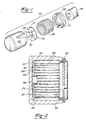
- Figure 1 is an exploded view of a bearing for a universal joint according to the present invention.
- Figure 2 is a cross-sectional view of a bearing prior to being assembled.
- Figure 3 shows the inventive bearing when fully assembled.
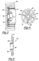
- Figure 4 is an end view of the inventive thrust washer.
- Figure 5 is a cross-sectional view along line 5-5 as shown in Figure 4.
- Figure 1 shows a bearing assembly 20 for use in a universal joint.
- a bearing cup 22 supports a trunnion 24.
- a seal 26 is received at an outer end of bearing cup 22.
- Bearing needles 28 extend between seal 26 and the inner end of bearing cup 22.
- Thrust washer 30 is disposed at an inner end of bearing cup 22.
- An inner face of thrust washer 30 has lubricant grooves 31 extending radially outwardly at a tangent to a central bore 32. Lubricant flows along a central bore 33 in trunnion 24, through central bore 32, and then may flow radially outwardly through grooves 31. As will be explained below, similar grooves are formed on an outer face of thrust washer 30. A plurality of nibs 34 are formed on the rear face of thrust washer 30. Nibs 34 maintain bearing needles in position until the universal joint is fully assembled, as will be explained below.
- FIG. 2 shows bearing 20 prior to being fully assembled into the universal joint. Trunnion 24 is not mounted within the bearing cup 22.
- the thrust washer 30 is shown biased away from the inner wall 35 of the bearing cup 22 by nibs 34. As shown, a trough 34t surrounds the nib 34.
- a locator member 36 is formed about central bore 32. Locator 36 insures that an assembler will not place thrust washer 30 within bearing cup 22 in the improper orientation. That is, should the assembler place thrust washer 30 within bearing cup 22 such that the nibs 34 face outwardly, rather than as shown in this figure, locator 36 prevents further assembly. The assembler thus is notified that the thrust washer 30 has been improperly assembled.
- a notch 38 is formed at a radially outer portion of the thrust washer 30.
- Notch 38 supports an inner end 40 of bearing needles 28.
- An outer end 42 of the bearing needles 28 is supported in a lip 44 of seal 26.
- Nibs 34 bias the thrust washer 30 away from an inner face 35 of bearing cup 22 against bearing needles 28. Bearing needles 28 are thus supported on notch 38 and seal 26, as shown.
- Nibs 34 eliminate this concern.
- Figure 3 shows the bearing 20 now having been fully assembled in a universal joint yoke 45.
- Trunnion 24 compresses thrust washer 30.
- Nibs 34 no longer bias thrust washer 30 away from end wall 35. Instead, the nibs 34 are collapsed and have expanded into trough 34t.
- the bearing needles 28 are no longer caught between notch 38 and lip 44.
- Trunnion 24 is now received within the bearing cup 22, and the bearing needles 28 can no longer fall radially inwardly.
- the inventive thrust washer is formed of a molded plastic, this rubbing will not lead to metal debris within the bearing 20.
- the thrust washer is molded of a plastic, tighter dimensional controls may be maintained on the thrust washer, and the above-described features may be designed into the thrust washer.
- Figure 4 is a view of an outer face of thrust washer 30.
- Lubricant grooves 31 on the inner face and nibs 34 are shown in phantom.
- lubricant grooves 46 extend radially outwardly and generally tangent to bore 32.
- Lubricant grooves 46 extend radially from a central groove 48 which communicates the lubricant to the grooves 46.
- the use of the angled lubricant grooves on each face of the thrust washer insures adequate lubrication to bearing assembly 20.
- the central portion 50 of thrust washer 30 extends further towards the trunnion than radially outer portions. In this way, thrust washer 30 insures that the majority of the contact between the trunnion and the thrust washer is adjacent to the axis of rotation. It is desirable to maintain the bulk of the contact as close as possible to the axis of rotation.
- the front face is angled at a small angle A. Preferably, angle A is less than five degrees. In one specific embodiment, angle A was two degrees.
- Bearing cup 22 is initially assembled by placing thrust washer 30 within the bearing cup.
- Bearing needles 28 are then placed within bearing cup 22, as is seal 26.
- Nibs 34 ensure that thrust washer 30 is biased outwardly such that the bearing needles 28 are caught between notch 38 and lip 44.
- the universal joint is then assembled as is known.
- Trunnion 24 is mounted within the bearing 22, and the bearing is mounted in yoke 45.
- Nibs 34 are compressed and thrust washer 30 moves away from the position where it had captured the bearing needles 28.
- Bearing needles 28 are now provided with some axial freedom of movement, and can function properly.
- the thrust washer is preferably molded from a strong plastic.
- a glass-reinforced nylon was utilized to form the thrust washer.
- a nylon available under the trade name Zytel from DuPont may be used.
- the nibs are relatively small, and in one application were .015 inch for a thrust washer having an approximate thickness of.097 inch at areas other than the nibs.
Landscapes
- Engineering & Computer Science (AREA)
- General Engineering & Computer Science (AREA)
- Mechanical Engineering (AREA)
- Chemical & Material Sciences (AREA)
- Oil, Petroleum & Natural Gas (AREA)
- Sliding-Contact Bearings (AREA)
- Rolling Contact Bearings (AREA)
Claims (18)
- Ensemble formant palier pour joint à cardan comportant :caractérisé en ce qu'une entaille (38) est formée en une partie radialement extérieure d'une face externe de ladite rondelle de butée supportant ladite extrémité intérieure de ladite pluralité d'aiguilles de roulement et pousse ladite pluralité d'aiguilles de roulement radialement vers l'extérieur vers ladite paroi cylindrique de ladite cloche de palier.une cloche de palier (22) définissant une paroi d'extrémité et une paroi cylindrique définissant un espace de logement intérieur de palier,une pluralité d'aiguilles de roulement (28) logées à l'intérieur dudit espace de logement de palier,un joint d'étanchéité (26) disposé à une extrémité extérieure de ladite cloche de palier ; etune rondelle de butée (30) disposée entre ladite paroi d'extrémité de ladite cloche de palier et une extrémité intérieure de ladite pluralité d'aiguilles de roulement,
- Ensemble formant palier selon la revendication 1, caractérisé en ce que lesdites aiguilles de roulement (28) sont poussées de plus dans la structure dudit joint d'étanchéité (26) afin de supporter lesdites aiguilles de roulement à l'intérieur de ladite cloche de palier (22).
- Ensemble formant palier selon la revendication 1, dans lequel ladite rondelle de butée (30) est caractérisée en ce qu'elle comporte, en outre, des organes élastiques (34) formés sur une face intérieure de ladite rondelle de butée, lesdits organes élastiques poussant ladite rondelle de butée en l'éloignant de ladite paroi d'extrémité.
- Ensemble formant palier selon la revendication 1, caractérisé en ce que ladite rondelle de butée (30) est moulée à partir de nylon.
- Ensemble formant palier selon la revendication 1, caractérisé en ce qu'une face extérieure de ladite rondelle de butée (30) est munie d'une structure (36) empêchant que la rondelle de butée soit montée dans ladite cloche de palier (22) avec ladite face extérieure en regard de ladite paroi d'extrémité de ladite cloche de palier.
- Ensemble formant palier selon la revendication 5, caractérisé en ce que ladite structure (36) comporte un dôme s'étendant en s'éloignant de ladite face extérieure de ladite rondelle de butée.
- Ensemble formant palier selon la revendication 1, caractérisé en ce que ladite rondelle de butée (30) est munie d'une pluralité de gorges de lubrification (31, 46) s'étendant vers l'extérieur d'un alésage central (32) de ladite rondelle de butée, à la fois sur les surfaces internes et externes de ladite rondelle de butée.
- Ensemble formant palier selon la revendication 7, caractérisé en ce que ledit alésage central (32) permet le passage d'un lubrifiant et lesdites gorges (31, 46) s'étendent globalement selon une tangente audit alésage central.
- Ensemble formant palier selon la revendication 1, caractérisé en ce qu'une face extérieure de ladite rondelle de butée est formée de telle sorte qu'elle présente une partie globalement centrale (50) s'étendant davantage axialement vers l'extérieur que les parties radialement extérieures.
- Ensemble formant palier selon la revendication 9, caractérisé en ce que ladite face extérieure s'étend en avant de ladite partie radialement extérieure, vers ladite partie centrale (50), généralement suivant un angle (A).
- Ensemble formant palier selon la revendication 10, caractérisé en ce que ledit angle (A) est inférieur à 5 degrés.
- Ensemble formant palier selon la revendication 3, caractérisé en ce que lesdits organes élastiques (34) sont comprimés lorsque ledit ensemble formant palier (20) est monté dans un joint à cardan, de telle sorte que ladite rondelle de butée (30) ne pousse pas ladite pluralité d'aiguilles de roulement (28) contre ledit joint d'étanchéité (26) quand le joint à cardan est complètement assemblé.
- Ensemble formant palier selon la revendication 12, caractérisé en ce que ladite face extérieure de ladite rondelle de butée (30) est formée avec une structure (36) empêchant que ladite rondelle de butée soit montée dans ladite cloche de palier (22) avec ladite face extérieure en regard de ladite paroi d'extrémité de ladite cloche de palier.
- Ensemble formant palier selon la revendication 13, caractérisé en ce que ladite face extérieure de ladite rondelle de butée comporte des parties radialement extérieures ne s'étendant pas aussi loin, à partir de ladite paroi d'extrémité, que la partie centrale (50) de la face extérieure de ladite rondelle de butée qui vient au contact d'un tourillon (24) lorsque le joint à cardan est assemblé.
- Ensemble formant palier selon la revendication 14, caractérisé en ce que ladite face extérieure s'étend généralement suivant un angle (A) à partir d'une partie radialement extérieure jusqu'à ladite partie centrale (50).
- Ensemble formant palier selon la revendication 15, caractérisé en ce que ledit angle (A) est inférieur à 5 degrés.
- Procédé d'assemblage d'un palier pour joint à cardan comportant les étapes consistant à :prévoir une cloche de palier (22),prévoir une rondelle de butée (30) munie d'une entaille ayant une surface de support de palier (38) au voisinage d'une partie radialement extérieure et des organes élastiques (34) sur une face arrière de ladite rondelle de butée,monter ladite rondelle de butée dans ladite cloche de palier,monter une pluralité d'aiguilles de roulement (28) dans ladite cloche de palier,monter un joint d'étanchéité (26) à une extrémité extérieure de ladite cloche de palier, monter lesdits organes élastiques (34) sur ladite rondelle de butée poussant ladite surface de support de palier (38) sur ladite rondelle de butée contre ladite pluralité d'aiguilles de roulement (28), et poussant ladite pluralité d'aiguilles de roulement axialement vers l'extérieur contre ledit joint d'étanchéité de telle sorte que ladite pluralité d'aiguilles de roulement soit supportée à l'intérieur de ladite cloche de palier, etmonter ledit palier dans une arcade, et monter un tourillon (24) dans ladite cloche de palier, lesdits organes élastiques étant comprimés par ledit tourillon de telle sorte que ladite rondelle de butée ne pousse plus ladite pluralité d'aiguilles de roulement dans ledit joint d'étanchéité.
- Rondelle de butée destinée à être utilisée dans un ensemble formant palier, caractérisé en ce qu'elle comporte :une face extérieure ayant une extension (36) s'étendant axialement vers l'extérieur à une partie généralement centrale de ladite rondelle de butée (30) et une entaille avec une surface de support de palier adajcente à une partie radialement extérieure de ladite rondelle de butée, etune face intérieure munie d'une pluralité d'organes élastiques (34) s'étendant généralement en s'éloignant de ladite face intérieure, grâce à quoi ladite surface (38) de support de palier, de ladite rondelle de butée (30), pousse une pluralité d'aiguilles de roulement (28) dans une direction radiale vers l'extérieur contre une surface intérieure d'une cloche de palier (22) qui reçoit ladite rondelle de butée (30).
Applications Claiming Priority (3)
| Application Number | Priority Date | Filing Date | Title |
|---|---|---|---|
| US434376 | 1989-11-09 | ||
| US08/434,376 US5813916A (en) | 1995-05-03 | 1995-05-03 | Retained needle thrust washer |
| PCT/US1996/006084 WO1996035059A1 (fr) | 1995-05-03 | 1996-05-01 | Rondelle de butee pour la retenue de roulements a aiguilles |
Publications (2)
| Publication Number | Publication Date |
|---|---|
| EP0870121A1 EP0870121A1 (fr) | 1998-10-14 |
| EP0870121B1 true EP0870121B1 (fr) | 1999-11-24 |
Family
ID=23723973
Family Applications (1)
| Application Number | Title | Priority Date | Filing Date |
|---|---|---|---|
| EP96914566A Expired - Lifetime EP0870121B1 (fr) | 1995-05-03 | 1996-05-01 | Rondelle de butee pour la retenue de roulements a aiguilles |
Country Status (5)
| Country | Link |
|---|---|
| US (1) | US5813916A (fr) |
| EP (1) | EP0870121B1 (fr) |
| AU (1) | AU5788896A (fr) |
| DE (1) | DE69605324T2 (fr) |
| WO (1) | WO1996035059A1 (fr) |
Families Citing this family (20)
| Publication number | Priority date | Publication date | Assignee | Title |
|---|---|---|---|---|
| US6095925A (en) * | 1997-10-10 | 2000-08-01 | Dana Corporation | Seal assembly and seal guard for a universal joint |
| US6059663A (en) * | 1998-07-13 | 2000-05-09 | Neapco Inc. | One-piece sealing system for a universal joint assembly |
| US6129634A (en) * | 1998-11-13 | 2000-10-10 | Dana Corporation | Thrust washer for universal joint |
| US6336868B1 (en) | 1999-04-06 | 2002-01-08 | American Axle & Manufacturing, Inc. | Universal joint with thrust washer |
| US20030035603A1 (en) * | 2001-08-15 | 2003-02-20 | V.W. Kaiser Engineering, Inc. | Thrust bushing for steering kingpin assembly |
| DE10155761A1 (de) * | 2001-11-14 | 2004-05-19 | Spicer Gelenkwellenbau Gmbh & Co. Kg | Lagerungsanordnung für einen Zapfen, insbesondere eines Zapfenkreuzes eines Kreuzgelenkes |
| DE10204563B4 (de) * | 2002-02-04 | 2010-07-08 | Aktiebolaget Skf | Verfahren zum Einführen eines Zapfens in eine Lagerbüchse |
| GB2394437A (en) | 2002-10-23 | 2004-04-28 | Black & Decker Inc | Hammer including a piston with wear-reducing washers |
| US6827649B2 (en) * | 2003-03-12 | 2004-12-07 | American Axle & Manufacturing, Inc. | Universal joint with friction fit and bearing cup retainer |
| US6994627B2 (en) * | 2003-04-14 | 2006-02-07 | American Axle & Manufacturing, Inc. | Universal joint |
| US6855059B2 (en) * | 2003-04-14 | 2005-02-15 | American Axle & Manufacturing, Inc. | Universal joint with bearing cup retention thrust washer |
| US6893350B2 (en) * | 2003-05-08 | 2005-05-17 | American Axle & Manufacturing, Inc. | Universal joint with torsionally-compliant spider assembly |
| US7037199B2 (en) * | 2004-01-16 | 2006-05-02 | Federal-Mogul World Wide, Inc. | Universal joint washer baffle |
| DE202004006818U1 (de) * | 2004-04-28 | 2005-09-08 | Ab Skf | Lagerbüchse zur drehbaren Lagerung eines Zapfens |
| US7338378B1 (en) * | 2004-08-03 | 2008-03-04 | Torque-Traction Technologies Llc | Retainer for universal joint bearing cups |
| JP2007321944A (ja) * | 2006-06-05 | 2007-12-13 | Jtekt Corp | 十字軸継手の製造方法 |
| US7887422B2 (en) | 2007-08-02 | 2011-02-15 | American Axle & Manufacturing, Inc. | Universal joint with bearing cup retention mechanism |
| JP5348365B2 (ja) * | 2007-10-12 | 2013-11-20 | Nok株式会社 | ユニバーサルジョイント用密封装置 |
| US8490986B1 (en) | 2012-05-16 | 2013-07-23 | Arvinmeritor Technology, Llc | Steering knuckle assembly having a kingpin |
| US10156266B2 (en) | 2016-08-30 | 2018-12-18 | Arvinmeritor Technology, Llc | Universal joint having a retainer ring |
Family Cites Families (15)
| Publication number | Priority date | Publication date | Assignee | Title |
|---|---|---|---|---|
| US3070980A (en) * | 1960-09-21 | 1963-01-01 | Cleveland Steel Products Corp | Universal couplings |
| FR2033202A1 (fr) * | 1968-12-05 | 1970-12-04 | Gelenkwellenbau Gmbh | |
| GB1451482A (en) * | 1973-11-09 | 1976-10-06 | Gkn Transmissions Ltd | Hookes joints |
| AT364204B (de) * | 1975-12-11 | 1981-10-12 | Gelenkwellenbau Gmbh | Stirnanlaufscheibe fuer die lagerzapfen des zapfenkreuzes eines kreuzgelenkes |
| GB1477910A (en) * | 1975-12-11 | 1977-06-29 | Gkn Transmissions Ltd | Hookes type universal joints |
| DE2616020A1 (de) * | 1976-04-12 | 1977-10-20 | Schaeffler Ohg Industriewerk | Lagerbuechse fuer kreuzgelenkzapfen |
| FR2459899A1 (fr) * | 1979-06-27 | 1981-01-16 | Nadella | Palier combine a rondelle deformable |
| GB2082287A (en) * | 1980-08-19 | 1982-03-03 | Brd Co Ltd | Hookes Universal Joints |
| US4445875A (en) * | 1980-12-03 | 1984-05-01 | Matsui Universal Joint Manufacturing Company | Universal joint |
| DE3115659A1 (de) * | 1981-04-18 | 1982-11-04 | Gelenkwellenbau Gmbh, 4300 Essen | "stirnanlaufscheibe" |
| SU1211492A1 (ru) * | 1982-04-19 | 1986-02-15 | Волжское объединение по производству легковых автомобилей | Карданный шарнир |
| DE3337602A1 (de) * | 1983-10-15 | 1985-04-25 | FAG Kugelfischer Georg Schäfer KGaA, 8720 Schweinfurt | Bodenplatte fuer eine ueber waelzkoerper auf einem zapfen gelagerte buechse |
| FR2566071B1 (fr) * | 1984-06-15 | 1989-03-10 | Glaenzer Spicer Sa | Dispositif d'etancheite pour joint de cardan |
| DE3622657A1 (de) * | 1986-07-05 | 1988-01-14 | Skf Gmbh | Mit einer anlaufscheibe versehene lagerbuechse, insbesondere fuer kreuzgelenkzapfen |
| DE8709201U1 (fr) * | 1987-07-03 | 1987-08-20 | Skf Gmbh, 8720 Schweinfurt, De |
-
1995
- 1995-05-03 US US08/434,376 patent/US5813916A/en not_active Expired - Lifetime
-
1996
- 1996-05-01 DE DE69605324T patent/DE69605324T2/de not_active Expired - Fee Related
- 1996-05-01 AU AU57888/96A patent/AU5788896A/en not_active Abandoned
- 1996-05-01 EP EP96914566A patent/EP0870121B1/fr not_active Expired - Lifetime
- 1996-05-01 WO PCT/US1996/006084 patent/WO1996035059A1/fr active IP Right Grant
Also Published As
| Publication number | Publication date |
|---|---|
| WO1996035059A1 (fr) | 1996-11-07 |
| EP0870121A1 (fr) | 1998-10-14 |
| DE69605324D1 (de) | 1999-12-30 |
| AU5788896A (en) | 1996-11-21 |
| DE69605324T2 (de) | 2000-05-31 |
| US5813916A (en) | 1998-09-29 |
Similar Documents
| Publication | Publication Date | Title |
|---|---|---|
| EP0870121B1 (fr) | Rondelle de butee pour la retenue de roulements a aiguilles | |
| US7025679B2 (en) | Universal joint with bearing cup retention thrust washer | |
| US5725431A (en) | Thrust washer for universal joint having preloading thrust surfaces | |
| US4207757A (en) | Double cardan universal joint | |
| EP1471276B1 (fr) | Joint universel avec joint d'étanchéité pour vider des gaz | |
| US4627826A (en) | Multi-segment, non-flexible boot for mechanical joint | |
| US6264566B1 (en) | Thrust washer for universal joint | |
| EP1620656B1 (fr) | Articulation universelle avec deflecteur a etancheite incorporee et ensemble bague d'arret | |
| JP2002539390A (ja) | 支承球欠体を備えた軸受け | |
| EP1469214B1 (fr) | Joint universel | |
| US6158991A (en) | Scroll-type fluid machine in which a movable scroll member is elastically urged towards a fixed scroll member | |
| JPH11198825A (ja) | 車両構成部品用のダンパ | |
| GB2100337A (en) | A ball-and-socket joint | |
| US20020082093A1 (en) | Dust guard and cross assembly for a universal joint | |
| EP0394683A1 (fr) | Palier avec dispositif d'étanchéité pour arbres de transmission de véhicules à moteur | |
| US4605235A (en) | High thrust capacity shaft seal assembly for fuel pumps | |
| EP0425220B1 (fr) | Joint universel | |
| EP1469216B1 (fr) | Joint universel comprenant un dispositif d'étanchéité pour la coupelle de palier de ce joint universel | |
| US20030040368A1 (en) | Cross member unit for universal joints | |
| EP3850232B1 (fr) | Ensemble joint à rotule | |
| WO1995033139A1 (fr) | Rotule d'articulation a chapeau solidaire | |
| US10954995B2 (en) | Socket assembly and method of making | |
| US10895280B2 (en) | Socket assembly and method of making | |
| US6386982B1 (en) | Cross member unit with centering element | |
| CN219827643U (zh) | 用于旋转轴的支架 |
Legal Events
| Date | Code | Title | Description |
|---|---|---|---|
| PUAI | Public reference made under article 153(3) epc to a published international application that has entered the european phase |
Free format text: ORIGINAL CODE: 0009012 |
|
| 17P | Request for examination filed |
Effective date: 19971128 |
|
| AK | Designated contracting states |
Kind code of ref document: A1 Designated state(s): DE GB IT |
|
| GRAG | Despatch of communication of intention to grant |
Free format text: ORIGINAL CODE: EPIDOS AGRA |
|
| 17Q | First examination report despatched |
Effective date: 19990212 |
|
| GRAG | Despatch of communication of intention to grant |
Free format text: ORIGINAL CODE: EPIDOS AGRA |
|
| GRAH | Despatch of communication of intention to grant a patent |
Free format text: ORIGINAL CODE: EPIDOS IGRA |
|
| GRAH | Despatch of communication of intention to grant a patent |
Free format text: ORIGINAL CODE: EPIDOS IGRA |
|
| GRAA | (expected) grant |
Free format text: ORIGINAL CODE: 0009210 |
|
| AK | Designated contracting states |
Kind code of ref document: B1 Designated state(s): DE GB IT |
|
| REF | Corresponds to: |
Ref document number: 69605324 Country of ref document: DE Date of ref document: 19991230 |
|
| ITF | It: translation for a ep patent filed |
Owner name: SOCIETA' ITALIANA BREVETTI S.P.A. |
|
| PLBE | No opposition filed within time limit |
Free format text: ORIGINAL CODE: 0009261 |
|
| STAA | Information on the status of an ep patent application or granted ep patent |
Free format text: STATUS: NO OPPOSITION FILED WITHIN TIME LIMIT |
|
| 26N | No opposition filed | ||
| REG | Reference to a national code |
Ref country code: GB Ref legal event code: IF02 |
|
| PGFP | Annual fee paid to national office [announced via postgrant information from national office to epo] |
Ref country code: GB Payment date: 20020424 Year of fee payment: 7 |
|
| PG25 | Lapsed in a contracting state [announced via postgrant information from national office to epo] |
Ref country code: GB Free format text: LAPSE BECAUSE OF NON-PAYMENT OF DUE FEES Effective date: 20030501 |
|
| GBPC | Gb: european patent ceased through non-payment of renewal fee |
Effective date: 20030501 |
|
| PG25 | Lapsed in a contracting state [announced via postgrant information from national office to epo] |
Ref country code: IT Free format text: LAPSE BECAUSE OF NON-PAYMENT OF DUE FEES Effective date: 20050501 |
|
| PGFP | Annual fee paid to national office [announced via postgrant information from national office to epo] |
Ref country code: DE Payment date: 20060427 Year of fee payment: 11 |
|
| PG25 | Lapsed in a contracting state [announced via postgrant information from national office to epo] |
Ref country code: DE Free format text: LAPSE BECAUSE OF NON-PAYMENT OF DUE FEES Effective date: 20071201 |