EP0868301B1 - Embossing and laminating machine with embossing cylinders having different rotational speed - Google Patents
Embossing and laminating machine with embossing cylinders having different rotational speed Download PDFInfo
- Publication number
- EP0868301B1 EP0868301B1 EP96941807A EP96941807A EP0868301B1 EP 0868301 B1 EP0868301 B1 EP 0868301B1 EP 96941807 A EP96941807 A EP 96941807A EP 96941807 A EP96941807 A EP 96941807A EP 0868301 B1 EP0868301 B1 EP 0868301B1
- Authority
- EP
- European Patent Office
- Prior art keywords
- embossing
- protuberances
- cylinders
- alignment
- laminating machine
- Prior art date
- Legal status (The legal status is an assumption and is not a legal conclusion. Google has not performed a legal analysis and makes no representation as to the accuracy of the status listed.)
- Expired - Lifetime
Links
Images


Classifications
-
- B—PERFORMING OPERATIONS; TRANSPORTING
- B31—MAKING ARTICLES OF PAPER, CARDBOARD OR MATERIAL WORKED IN A MANNER ANALOGOUS TO PAPER; WORKING PAPER, CARDBOARD OR MATERIAL WORKED IN A MANNER ANALOGOUS TO PAPER
- B31F—MECHANICAL WORKING OR DEFORMATION OF PAPER, CARDBOARD OR MATERIAL WORKED IN A MANNER ANALOGOUS TO PAPER
- B31F1/00—Mechanical deformation without removing material, e.g. in combination with laminating
- B31F1/07—Embossing, i.e. producing impressions formed by locally deep-drawing, e.g. using rolls provided with complementary profiles
-
- B—PERFORMING OPERATIONS; TRANSPORTING
- B31—MAKING ARTICLES OF PAPER, CARDBOARD OR MATERIAL WORKED IN A MANNER ANALOGOUS TO PAPER; WORKING PAPER, CARDBOARD OR MATERIAL WORKED IN A MANNER ANALOGOUS TO PAPER
- B31F—MECHANICAL WORKING OR DEFORMATION OF PAPER, CARDBOARD OR MATERIAL WORKED IN A MANNER ANALOGOUS TO PAPER
- B31F2201/00—Mechanical deformation of paper or cardboard without removing material
- B31F2201/07—Embossing
- B31F2201/0707—Embossing by tools working continuously
- B31F2201/0715—The tools being rollers
- B31F2201/0717—Methods and means for forming the embossments
-
- B—PERFORMING OPERATIONS; TRANSPORTING
- B31—MAKING ARTICLES OF PAPER, CARDBOARD OR MATERIAL WORKED IN A MANNER ANALOGOUS TO PAPER; WORKING PAPER, CARDBOARD OR MATERIAL WORKED IN A MANNER ANALOGOUS TO PAPER
- B31F—MECHANICAL WORKING OR DEFORMATION OF PAPER, CARDBOARD OR MATERIAL WORKED IN A MANNER ANALOGOUS TO PAPER
- B31F2201/00—Mechanical deformation of paper or cardboard without removing material
- B31F2201/07—Embossing
- B31F2201/0707—Embossing by tools working continuously
- B31F2201/0715—The tools being rollers
- B31F2201/0723—Characteristics of the rollers
- B31F2201/0733—Pattern
- B31F2201/0735—Pattern inclined with respect to the axis of the roller
-
- B—PERFORMING OPERATIONS; TRANSPORTING
- B31—MAKING ARTICLES OF PAPER, CARDBOARD OR MATERIAL WORKED IN A MANNER ANALOGOUS TO PAPER; WORKING PAPER, CARDBOARD OR MATERIAL WORKED IN A MANNER ANALOGOUS TO PAPER
- B31F—MECHANICAL WORKING OR DEFORMATION OF PAPER, CARDBOARD OR MATERIAL WORKED IN A MANNER ANALOGOUS TO PAPER
- B31F2201/00—Mechanical deformation of paper or cardboard without removing material
- B31F2201/07—Embossing
- B31F2201/0707—Embossing by tools working continuously
- B31F2201/0715—The tools being rollers
- B31F2201/0753—Roller supporting, positioning, driving means
-
- B—PERFORMING OPERATIONS; TRANSPORTING
- B31—MAKING ARTICLES OF PAPER, CARDBOARD OR MATERIAL WORKED IN A MANNER ANALOGOUS TO PAPER; WORKING PAPER, CARDBOARD OR MATERIAL WORKED IN A MANNER ANALOGOUS TO PAPER
- B31F—MECHANICAL WORKING OR DEFORMATION OF PAPER, CARDBOARD OR MATERIAL WORKED IN A MANNER ANALOGOUS TO PAPER
- B31F2201/00—Mechanical deformation of paper or cardboard without removing material
- B31F2201/07—Embossing
- B31F2201/0758—Characteristics of the embossed product
- B31F2201/0761—Multi-layered
- B31F2201/0769—Multi-layered the layers being shifted
-
- B—PERFORMING OPERATIONS; TRANSPORTING
- B31—MAKING ARTICLES OF PAPER, CARDBOARD OR MATERIAL WORKED IN A MANNER ANALOGOUS TO PAPER; WORKING PAPER, CARDBOARD OR MATERIAL WORKED IN A MANNER ANALOGOUS TO PAPER
- B31F—MECHANICAL WORKING OR DEFORMATION OF PAPER, CARDBOARD OR MATERIAL WORKED IN A MANNER ANALOGOUS TO PAPER
- B31F2201/00—Mechanical deformation of paper or cardboard without removing material
- B31F2201/07—Embossing
- B31F2201/0782—Layout of the complete embossing machine, of the embossing line
-
- Y—GENERAL TAGGING OF NEW TECHNOLOGICAL DEVELOPMENTS; GENERAL TAGGING OF CROSS-SECTIONAL TECHNOLOGIES SPANNING OVER SEVERAL SECTIONS OF THE IPC; TECHNICAL SUBJECTS COVERED BY FORMER USPC CROSS-REFERENCE ART COLLECTIONS [XRACs] AND DIGESTS
- Y10—TECHNICAL SUBJECTS COVERED BY FORMER USPC
- Y10T—TECHNICAL SUBJECTS COVERED BY FORMER US CLASSIFICATION
- Y10T156/00—Adhesive bonding and miscellaneous chemical manufacture
- Y10T156/10—Methods of surface bonding and/or assembly therefor
- Y10T156/1002—Methods of surface bonding and/or assembly therefor with permanent bending or reshaping or surface deformation of self sustaining lamina
- Y10T156/1007—Running or continuous length work
- Y10T156/1023—Surface deformation only [e.g., embossing]
Definitions
- the invention relates to an embossing and laminating machine comprising a first embossing cylinder with a surface provided with a first set of protuberances, a second embossing cylinder with a surface provided with a second set of protuberances, the said two embossing cylinders forming a nip, and a first and a second pressure roller interacting with the first and the second embossing cylinder respectively; and in which the protuberances of the said first and the said second sets are made in such a way that in the said nip some of the protuberances of the first set coincide with some protuberances of the second set, while other protuberances of the first set are out of phase with corresponding protuberances of the second set.
- Embossing machines are commonly used for the processing of paper layers in order to form a semi-finished product intended for the production of rolls of toilet paper, rolls of kitchen towels, tissues, paper serviettes, and the like.
- EP-B-0,370,972 describes an embossing machine in which the cylinders are completely symmetrical with respect to each other and the protuberances are aligned in lines, all of which are inclined with respect to the axes of the corresponding cylinders.
- the embossing cylinders of these known devices are symmetrical and must be perfectly in phase, in such a way that in the area of their closest approach, where they are virtually in contact with each other at the positions of their protuberances and where the two layers are joined by pressure and gluing, there is an exact correspondence between all the protuberances of one cylinder and the corresponding protuberances of the other cylinder.
- the protuberances of one cylinder are disposed in a right-hand spiral and the protuberances of the other are disposed in a left-hand spiral, the spirals having equal and opposite inclinations with respect to the axes of the corresponding cylinders.
- the two embossing cylinders are kept exactly in phase and are adjusted so as to keep the protuberances of one cylinder always exactly in phase with the protuberances of the other cylinder.
- the two cylinders are connected mechanically by means of a pair of gears with devices for the resetting of the play in their engagement.
- the adjustment of the embossing machine is an extremely lengthy and complex operation, particularly as a result of the very small dimensions of the protuberances, the machining tolerances, the static deformations due to the inherent weight and to the embossing stresses, and the thermal deformations due to the heat generated by the compression of the coating of the pressure rollers in normal operating conditions.
- embossing cylinders made to produce a strip material as described in EP-A-0,426,548 are subject to crushing in circumscribed areas (areas of contact) much more rapidly than conventional embossing cylinders designed to operate with exact coincidence between all the protuberances of one cylinder and all the corresponding protuberances of the other cylinder in the lamination area, and a consequent distribution of the stresses over a large surface area.
- the object of the present invention is to produce an embossing and laminating machine which requires no phase matching between the embossing cylinders and which at the same time eliminates the disadvantage of having the pressure concentrating on, and consequently crushing, the protuberances on the cylinders.
- a transmission system between the embossing cylinders which permits slippage between the cylinders and does not keep the cylinders in phase.
- This solution to the aforementioned problems is based on the recognition of the fact that if the protuberances of the cylinders correspond to each other in certain areas only, and not over the whole line of contact in the lamination nip between the two embossing cylinders, it is no longer necessary to keep the cylinders in phase with each other.
- the slippage may be of the order of 0.5-3 ⁇ .
- the use of a belt transmission has the further advantage of reducing the construction and maintenance costs of the transmission system.
- the lubrication problems typical of gear systems used hitherto for transmission of the motion are also avoided, and transmission noise is also reduced.
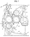
- Two embossing cylinders 3 and 5 disposed with parallel axes and having their surfaces provided with protuberances for embossing, are mounted on the frame of the machine 1. In the nip formed by the two cylinders 3 and 5, the protuberances (or rather some of them, as will be explained subsequently) are in contact with each other.
- the embossing cylinder 3 interacts with a pressure roller 7 which may also be provided with an embossed surface, or may be covered with a yielding material such as rubber or the like.
- the number 9 indicates a second pressure roller similar to the roller 7 and interacting with the embossing cylinder 5.
- the two pressure rollers 7 and 9 are mounted on corresponding moving elements 7A and 9A which are hinged and subject to an elastic force, for example through two cylinder and piston systems 7B, 9B which press the corresponding pressure rollers against the corresponding embossing cylinders 3 and 5.
- N3 and N5 indicate two layers of paper material or the like which are fed between the embossing cylinder 3 and the pressure roller 7 and between the embossing cylinder 5 and the pressure roller 9 respectively, so that they are embossed separately.
- the two embossed layers remain engaged with the corresponding embossing cylinders 3 and 5 and, after an adhesive has been applied by the unit 14 to the protuberances of the layer N3, are joined together in the nip between the two embossing cylinders 3 and 5, where the protuberances of one embossing cylinder move at a distance which is less than the combined thickness of the two layers N3 and N5 from the protuberances of the other embossing cylinder.
- the two embossing cylinders 3 and 5 are made with protuberances P3 and P5 distributed in such a way that, in the area where the layers are joined, only some of the protuberances P3 coincide with corresponding protuberances P5, while in the other areas there is no coincidence.
- the two embossing cylinders 3, 5 may be made in such a way that they have the same pattern embossed on both cylinders, but disposed at inclinations such that there is no superimposition, in other words correspondence, between all the protuberances of one cylinder and all the protuberances of the other cylinder, but there is superimposition or coincidence in certain areas.
- the protuberances P3 of the first set are aligned in a first and second direction of alignment indicated by Lx 3 and Ly 3 , forming between them an angle ⁇ other than zero.
- the protuberances P3 are disposed with the same interval along Lx 3 and along Ly 3 , but this need not be so.
- the direction Lx 3 forms an angle ⁇ 3 of 2° with the direction of the axis A3 of the first embossing cylinder 3.
- the protuberances P5 of the second set, on the embossing cylinder 5, are aligned in a third and fourth direction of alignment, indicated by Lx 5 and Ly 5 in Fig. 3.
- the directions of alignment Lx 5 and Ly 5 form between them the same angle ⁇ (or at least an angle very close to ⁇ , for example with a variation of approximately 1-3°), and are orientated in the same direction with respect to the axis A5 of the embossing cylinder 5.
- the direction Lx 5 is inclined downwards from left to right in Fig. 3, as is the direction Lx 3 in Fig. 2.
- the angle ⁇ 5 formed by the third direction of alignment Lx 5 with the axis A5 of the embossing cylinder 5 is, in this embodiment, different from the angle ⁇ 5 and is equal to 6°.
- Protuberances P3' and P5' are impressed on the two layers N3 and N5 in a pattern corresponding to that formed by the protuberances P3 and P5 on the two embossing cylinders 3 and 5 respectively. Consequently, after the two layers have been joined, there is no superimposition or coincidence of each protuberance of one layer with a corresponding protuberance of the other layer, but, as shown in Fig. 4, there is a correspondence in certain areas. The areas in which the protuberances coincide are separated from each other by areas in which the protuberances on one layer do not coincide with the protuberances of the other layer.
- the areas in which the protuberances P3' and P5' coincide are aligned in two alignments which are not parallel to the axes A3 and A5 of the two embossing cylinders 3 and 5. This means that, as the two layers N3 and N5 are joined, the protuberances P3 and P5 of the two embossing cylinders come into contact gradually in the area of lamination (in other words, of joining) of the strips, with an advantageous reduction in the vibration of the machine, mechanical stresses and noise.
- Lx 3 ', Ly 3 ' and Lx 5 ', Ly 5 ' indicate the directions of alignment of the protuberances P3' and P5' on the first and second layer respectively.
- the letter F indicates the direction of advance of the strip material leaving the embossing machine.
- Fig. 6 shows a schematic enlargement of Fig. 5, where the areas of coincidence of the protuberances P3' and P5' are clearly visible.
- protuberances of truncated pyramidal form which are the most common. These are easily produced using simple machining processes, for example by routing. In this case, the directions of alignment advantageously coincide with the directions of the diagonals of the quadrilateral bases of the truncated pyramids. However, different forms of protuberance are not excluded.
- the inclination characteristics described above of the directions of alignment of the protuberances may be uniform over the whole of the corresponding cylinder; in other words, the directions Lx 3 , Ly 3 , Lx 5 and Ly 5 may have the same inclination over the whole longitudinal development of the embossing cylinder 3 or 5 respectively.
- this is not essential, and the inclination of the directions of alignment may vary gradually along the axis of the cylinder, or may vary over successive sections of the cylinder.
- the embossing cylinders 3, 5 are made according to the illustrations in Figs. 2-6 and in the case in which they are made with protuberances P3, P5 disposed at different intervals so as to obtain contact between the protuberances in certain areas, in order to prevent deterioration of the embossing cylinders as a result of crushing in certain areas only, which would rapidly cause them to become unserviceable, according to the invention the cylinders are rotated by means of a transmission which permits slippage between the two cylinders and therefore permits the cylinders to move out of phase.
- Fig. 1 shows an example of an embodiment of this type of transmission, which uses a flat belt 53 running around a driving pulley 51.
- the flat belt 53 runs round a pulley 55 keyed to the axle of the cylinder 3 and round a pulley 57 keyed to the axle of the cylinder 5.
- the outer face of the belt runs round the pulley 55 and its inner face runs round the pulley 57.
- the number 59 indicates a tensioning pulley which allows the gap between the cylinders 3 and 5 to be adjusted.
- this type of transmission is not capable of maintaining the phase matching between the two pulleys 53, 55, and therefore slight slippages or movements out of phase are inevitable between the two cylinders. Whereas this phenomenon would be totally unacceptable in the embossing method using conventional tip-to-tip joining, according to the present invention it is precisely this characteristic of the transmission that is used to obtain the advantages and results described, namely the distribution of the crushing, increase in the service life of the cylinders, reduction in adjustment and maintenance operations, and the total elimination of the initial adjustment of the cylinders. A further advantage is the considerable reduction in transmission noise.
- the two embossing cylinders 3,5 To keep the contact pressure constant, it is possible for the two embossing cylinders 3,5 to be thermostatically controlled. It has been found that, by adjusting the embossing cylinders 3, 5 in such a way that they have a gap of 0.05 mm between them when the machine is cold, this gap is eliminated or considerably reduced after twenty minutes of operation, owing to the radial expansion of the embossing cylinders due to the rise in temperature during operation (caused by the interaction with the pressure rollers, which generates heat).
- thermostatic control system for example using a constant-temperature heat transfer fluid which circulates in the embossing cylinders 3, 5, it is possible to bring the temperature of the cylinders to a steady level before the start of the operating cycle, thereby setting the correct gap between the protuberances, which then remains unchanged throughout the operation.
- a system for controlling the pressure between the embossing cylinders 3, 5 which maintains this pressure at a constant level.
- This system is shown schematically in Fig. 1.
- the second embossing cylinder 5 and the second pressure roller 9 are carried by an oscillating moving element 16, pivoted at 16A on the structure of the machine and pressed by a cylinder and piston actuator 18 against a fixed stop 20.
- a movable and adjustable stop 22 carried by an extension 24 of the moving element 16 interacts with the fixed stop 20.
- the fixed stop is provided with a load cell which sends a signal proportional to the force exerted by the moving stop 22 to the control unit.
- the belt transmission between the embossing cylinders 3 and 5 has considerable advantages, as mentioned previously.
- the principal object of the present invention may also be achieved with a different type of transmission, for example a gear transmission constructed in such a way that the two embossing cylinders do not remain in phase, in other words in such a way that a slight difference in peripheral velocity, of the order of 1-2 ⁇ for example, is maintained between the cylinders 3 and 5.
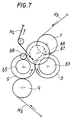
- Fig. 7 shows a gear transmission system capable of achieving this result.
- Two gear wheels 63 and 65 are keyed to the axles of the two cylinders 3 and 5 respectively.
- the two gear wheels 63, 65 do not engage directly, but have three further gear wheels 67, 68, 69 located between them, the last of which is an idle wheel, while the wheels 67, 68 are keyed to a single auxiliary axle.
- the idle wheel 68 allows the two cylinders 3 and 5 to rotate in opposite directions.
Applications Claiming Priority (3)
| Application Number | Priority Date | Filing Date | Title |
|---|---|---|---|
| IT95FI000249A IT1278803B1 (it) | 1995-12-05 | 1995-12-05 | Gruppo goffratore-laminatore, con cilindri goffratori non fasati e relativo metodo di goffratura |
| ITFI950249 | 1995-12-05 | ||
| PCT/IT1996/000238 WO1997020687A1 (en) | 1995-12-05 | 1996-12-02 | Embossing and laminating machine with embossing cylinders having different rotational speed |
Publications (2)
| Publication Number | Publication Date |
|---|---|
| EP0868301A1 EP0868301A1 (en) | 1998-10-07 |
| EP0868301B1 true EP0868301B1 (en) | 1999-10-13 |
Family
ID=11351429
Family Applications (1)
| Application Number | Title | Priority Date | Filing Date |
|---|---|---|---|
| EP96941807A Expired - Lifetime EP0868301B1 (en) | 1995-12-05 | 1996-12-02 | Embossing and laminating machine with embossing cylinders having different rotational speed |
Country Status (17)
| Country | Link |
|---|---|
| US (1) | US6053232A (pt) |
| EP (1) | EP0868301B1 (pt) |
| JP (1) | JP2000501348A (pt) |
| KR (1) | KR19990071899A (pt) |
| CN (1) | CN1203549A (pt) |
| AT (1) | ATE185515T1 (pt) |
| AU (1) | AU1108397A (pt) |
| BR (1) | BR9611684A (pt) |
| CA (1) | CA2239373A1 (pt) |
| DE (1) | DE69604696T2 (pt) |
| ES (1) | ES2138391T3 (pt) |
| GR (1) | GR3032216T3 (pt) |
| IL (1) | IL124775A (pt) |
| IT (1) | IT1278803B1 (pt) |
| PL (1) | PL327327A1 (pt) |
| RU (1) | RU2162415C2 (pt) |
| WO (1) | WO1997020687A1 (pt) |
Families Citing this family (42)
| Publication number | Priority date | Publication date | Assignee | Title |
|---|---|---|---|---|
| US6264872B1 (en) * | 1997-12-30 | 2001-07-24 | Kimberly-Clark Worldwide, Inc. | Method of forming thin, embossed, textured barrier films |
| BR9908459A (pt) | 1998-03-02 | 2000-11-14 | Perini Fabio Spa | Método e dispositivo para a produção de um material em manta gofrado e produto feito deste modo |
| EP1666241A2 (en) * | 1998-08-10 | 2006-06-07 | Hunt Technology Limited | Improvements relating to methods of thermal lamination |
| US6251207B1 (en) * | 1998-12-31 | 2001-06-26 | Kimberly-Clark Worldwide, Inc. | Embossing and laminating irregular bonding patterns |
| IT1307887B1 (it) | 1999-06-18 | 2001-11-19 | Perini Fabio Spa | Metodo e dispositivo di goffratura per la produzione di materialenastriforme multivelo, e prodotto cosi' ottenuto. |
| IT246987Y1 (it) * | 1999-08-06 | 2002-05-02 | C M G Costruzioni Meccaniche G | Macchina trasformabile per la alvorazione superficiale di carta |
| IT1313809B1 (it) * | 1999-11-02 | 2002-09-23 | Giovanni Gambini | Macchina goffratrice multiuso per produrre carta goffrata |
| DE10036292A1 (de) * | 2000-07-26 | 2002-02-07 | Jagenberg Papiertech Gmbh | Prägevorrichtung zur Erzeugung einer Haftung zwischen Lagen aus Tissue-Material |
| US6602577B1 (en) | 2000-10-03 | 2003-08-05 | The Procter & Gamble Company | Embossed cellulosic fibrous structure |
| ITFI20010223A1 (it) * | 2001-11-26 | 2003-05-26 | Perini Fabio Spa | Cilindro goffratore con camicia intercambiabile e con sistema di bloccaggio frontale della camicia, e gruppo goffratore comprendente detto |
| WO2003045680A1 (en) | 2001-11-26 | 2003-06-05 | Fabio Perini S.P.A. | Cylinder with interchangeable sleeve, method of manufacturing the same and associated unit |
| ITFI20020053A1 (it) | 2002-03-29 | 2003-09-29 | Perini Fabio Spa | Metodo e dispositivo per la produzione di un materiale nastriforme goffrato e manufatto ottenuto con detto metodo |
| ITFI20020061A1 (it) * | 2002-04-12 | 2003-10-13 | Perini Fabio Spa | Dispositivo e metodo di accoppiamento di veli per la formazione di manufatti in foglio e manufatti cosi'ottenuti |
| ITFI20020113A1 (it) * | 2002-06-26 | 2003-12-29 | Perini Fabio Spa | Dispositivo goffratore e laminatore con gruppo di cilindri goffratoriintercambiabile |
| ITFI20030015A1 (it) * | 2003-01-17 | 2004-07-18 | Fabio Perini | Dispositivo e metodo per eseguire l'unione di veli di carta |
| ITFI20030134A1 (it) | 2003-05-15 | 2004-11-16 | Perini Fabio Spa | Rullo a bombatura variabile per dispositivi di lavorazione di materiale nastriforme continuo e dispositivo comprendente detto rullo |
| KR100703116B1 (ko) * | 2005-12-09 | 2007-04-06 | 윤병현 | 복층 페이퍼 시트지 제조장치 |
| ITFI20060072A1 (it) * | 2006-03-15 | 2007-09-16 | Perini Fabio Spa | Rullo goffratore e relativo procedimento per la sua produzione |
| ITFI20060245A1 (it) | 2006-10-11 | 2008-04-12 | Delicarta Spa | Un materiale in carta con elevate caratteristiche detergenti e metodo per la sua produzione |
| ITFI20070048A1 (it) * | 2007-02-27 | 2008-08-28 | Perini Fabio Spa | Gruppo goffratore multi-funzione |
| ITFI20070162A1 (it) * | 2007-07-17 | 2009-01-18 | Futura Spa | Dispositivo per il trattamento di materiale cartaceo nastriforme. |
| ITFI20070163A1 (it) | 2007-07-18 | 2009-01-19 | Perini Fabio Spa | "materiale cartaceo goffrato, metodo e dispositivo per la sua produzione" |
| CN101804704A (zh) * | 2010-04-14 | 2010-08-18 | 全利机械股份有限公司 | 纤维制品压花装置 |
| US9220638B2 (en) | 2010-09-10 | 2015-12-29 | The Procter & Gamble Company | Deformed web materials |
| US9067357B2 (en) | 2010-09-10 | 2015-06-30 | The Procter & Gamble Company | Method for deforming a web |
| US8657596B2 (en) | 2011-04-26 | 2014-02-25 | The Procter & Gamble Company | Method and apparatus for deforming a web |
| US9452089B2 (en) | 2011-04-26 | 2016-09-27 | The Procter & Gamble Company | Methods of making absorbent members having density profile |
| US9452093B2 (en) | 2011-04-26 | 2016-09-27 | The Procter & Gamble Company | Absorbent members having density profile |
| US9028652B2 (en) | 2011-04-26 | 2015-05-12 | The Procter & Gamble Company | Methods of making bulked absorbent members |
| US9439815B2 (en) | 2011-04-26 | 2016-09-13 | The Procter & Gamble Company | Absorbent members having skewed density profile |
| US9440394B2 (en) | 2011-04-26 | 2016-09-13 | The Procter & Gamble Company | Methods of mechanically deforming materials |
| US9452094B2 (en) | 2011-04-26 | 2016-09-27 | The Procter & Gamble Company | Absorbent members having density profile |
| EP2701651B1 (en) | 2011-04-26 | 2016-07-20 | The Procter and Gamble Company | Bulked absorbent members |
| US9534325B2 (en) | 2011-04-26 | 2017-01-03 | The Procter & Gamble Company | Methods of making absorbent members having skewed density profile |
| US10011953B2 (en) | 2011-04-26 | 2018-07-03 | The Procter & Gamble Company | Bulked absorbent members |
| US9079739B2 (en) * | 2012-11-02 | 2015-07-14 | The Procter & Gamble Company | Apparatus for controlling the nip force/pressure between two rotating cylinders |
| US9073282B2 (en) | 2012-11-02 | 2015-07-07 | The Procter & Gamble Company | Process for controlling the nip force/pressure between two rotating cylinders |
| US20150298420A1 (en) * | 2012-11-16 | 2015-10-22 | Sca Hygiene Products Ab | Method for embossing a multi-ply paper product and an embossed multi-ply paper product |
| ITFI20130112A1 (it) | 2013-05-14 | 2014-11-15 | Perini Engraving S R L | Rullo goffratore, gruppo goffratore comprendente tale rullo, metodo di goffratura e prodotto ottenuto |
| ES2673602T3 (es) | 2014-10-13 | 2018-06-25 | Fabio Perini S.P.A. | Rodillo para procesar un material en banda continuo y dispositivo que comprende dicho rodillo |
| JP6689637B2 (ja) * | 2016-03-22 | 2020-04-28 | 大王製紙株式会社 | キッチンペーパー |
| JP2021532945A (ja) | 2018-08-22 | 2021-12-02 | ザ プロクター アンド ギャンブル カンパニーThe Procter & Gamble Company | 使い捨て吸収性物品 |
Family Cites Families (6)
| Publication number | Priority date | Publication date | Assignee | Title |
|---|---|---|---|---|
| US3414459A (en) * | 1965-02-01 | 1968-12-03 | Procter & Gamble | Compressible laminated paper structure |
| US3961119A (en) * | 1973-03-15 | 1976-06-01 | Kimberly-Clark Corporation | Embossed paper toweling and method of production |
| US4742968A (en) * | 1986-05-07 | 1988-05-10 | Young Engineering, Inc. | Beam winder and method of using same |
| IT1225324B (it) * | 1988-11-23 | 1990-11-06 | Perini Finanziaria Spa | Macchina per la trasformazione della carta con cilindri goffratori cooperanti per l'accoppiamento punta-punta di due nastri di carta da essi goffrati |
| FR2653793B1 (pt) * | 1989-10-30 | 1992-01-03 | Kaysersberg Sa | |
| MX9300424A (es) * | 1992-11-06 | 1994-05-31 | Kimberly Clark Co | Tela laminada fibrosa y metodo y aparato para la fabricacion de la misma. |
-
1995
- 1995-12-05 IT IT95FI000249A patent/IT1278803B1/it active IP Right Grant
-
1996
- 1996-12-02 IL IL12477596A patent/IL124775A/en not_active IP Right Cessation
- 1996-12-02 CN CN96198842A patent/CN1203549A/zh active Pending
- 1996-12-02 DE DE69604696T patent/DE69604696T2/de not_active Expired - Fee Related
- 1996-12-02 WO PCT/IT1996/000238 patent/WO1997020687A1/en active IP Right Grant
- 1996-12-02 PL PL96327327A patent/PL327327A1/xx unknown
- 1996-12-02 AT AT96941807T patent/ATE185515T1/de not_active IP Right Cessation
- 1996-12-02 US US09/077,230 patent/US6053232A/en not_active Expired - Fee Related
- 1996-12-02 ES ES96941807T patent/ES2138391T3/es not_active Expired - Lifetime
- 1996-12-02 AU AU11083/97A patent/AU1108397A/en not_active Abandoned
- 1996-12-02 BR BR9611684A patent/BR9611684A/pt not_active IP Right Cessation
- 1996-12-02 EP EP96941807A patent/EP0868301B1/en not_active Expired - Lifetime
- 1996-12-02 KR KR1019980704185A patent/KR19990071899A/ko active IP Right Grant
- 1996-12-02 RU RU98112271/12A patent/RU2162415C2/ru active
- 1996-12-02 CA CA002239373A patent/CA2239373A1/en not_active Abandoned
- 1996-12-02 JP JP9521134A patent/JP2000501348A/ja not_active Ceased
-
1999
- 1999-12-22 GR GR990403303T patent/GR3032216T3/el unknown
Also Published As
| Publication number | Publication date |
|---|---|
| IL124775A (en) | 2001-04-30 |
| RU2162415C2 (ru) | 2001-01-27 |
| EP0868301A1 (en) | 1998-10-07 |
| BR9611684A (pt) | 1999-03-02 |
| ITFI950249A0 (pt) | 1995-12-05 |
| PL327327A1 (en) | 1998-12-07 |
| IL124775A0 (en) | 1999-01-26 |
| WO1997020687A1 (en) | 1997-06-12 |
| US6053232A (en) | 2000-04-25 |
| IT1278803B1 (it) | 1997-11-28 |
| ATE185515T1 (de) | 1999-10-15 |
| CN1203549A (zh) | 1998-12-30 |
| GR3032216T3 (en) | 2000-04-27 |
| DE69604696T2 (de) | 2000-06-21 |
| ITFI950249A1 (it) | 1997-06-05 |
| KR19990071899A (ko) | 1999-09-27 |
| DE69604696D1 (de) | 1999-11-18 |
| CA2239373A1 (en) | 1997-06-12 |
| ES2138391T3 (es) | 2000-01-01 |
| JP2000501348A (ja) | 2000-02-08 |
| AU1108397A (en) | 1997-06-27 |
Similar Documents
| Publication | Publication Date | Title |
|---|---|---|
| EP0868301B1 (en) | Embossing and laminating machine with embossing cylinders having different rotational speed | |
| EP0868303B1 (en) | Embossing and laminating machine and method with cylinders with distributed contact areas | |
| EP0868302B1 (en) | Embossing and laminating machine for gluing embossed layers | |
| US6863107B2 (en) | Device for applying a spot embossing pattern to a web of multi-ply tissue paper | |
| EP1054764B1 (en) | Embossing and laminating device for web material | |
| JP2659118B2 (ja) | シート状材料,特に布帛を強化する方法およびその装置 | |
| KR100399866B1 (ko) | 2개이상의 플라이로 이루어진 웨브재료를 엠보싱 및 적층하는 장치 | |
| EP1434687B1 (en) | Device and method for applying a spot embossing pattern to a web of multi-ply tissue paper | |
| CN100340398C (zh) | 用于层压辊的间隙调整器 | |
| US6832546B2 (en) | Embossing device | |
| US6289960B1 (en) | Apparatus having a wrapped roll for making a single faced corrugated board | |
| US3129659A (en) | Embossing apparatus | |
| GB2308392A (en) | Single-faced corrugated cardboard sheet making machine | |
| GB2304124A (en) | Corrugating:single facer:pressing material onto fluted roll | |
| JP2004360827A (ja) | ダブルベルトマシーン用のベルト駆動装置と同駆動装置を備えたダブルベルトマシーン |
Legal Events
| Date | Code | Title | Description |
|---|---|---|---|
| PUAI | Public reference made under article 153(3) epc to a published international application that has entered the european phase |
Free format text: ORIGINAL CODE: 0009012 |
|
| 17P | Request for examination filed |
Effective date: 19980615 |
|
| AK | Designated contracting states |
Kind code of ref document: A1 Designated state(s): AT CH DE ES FI FR GB GR LI NL SE |
|
| GRAG | Despatch of communication of intention to grant |
Free format text: ORIGINAL CODE: EPIDOS AGRA |
|
| 17Q | First examination report despatched |
Effective date: 19981208 |
|
| GRAG | Despatch of communication of intention to grant |
Free format text: ORIGINAL CODE: EPIDOS AGRA |
|
| GRAH | Despatch of communication of intention to grant a patent |
Free format text: ORIGINAL CODE: EPIDOS IGRA |
|
| GRAH | Despatch of communication of intention to grant a patent |
Free format text: ORIGINAL CODE: EPIDOS IGRA |
|
| GRAA | (expected) grant |
Free format text: ORIGINAL CODE: 0009210 |
|
| AK | Designated contracting states |
Kind code of ref document: B1 Designated state(s): AT CH DE ES FI FR GB GR LI NL SE |
|
| REF | Corresponds to: |
Ref document number: 185515 Country of ref document: AT Date of ref document: 19991015 Kind code of ref document: T |
|
| REG | Reference to a national code |
Ref country code: CH Ref legal event code: EP |
|
| REG | Reference to a national code |
Ref country code: CH Ref legal event code: NV Representative=s name: BOVARD AG PATENTANWAELTE |
|
| REF | Corresponds to: |
Ref document number: 69604696 Country of ref document: DE Date of ref document: 19991118 |
|
| ET | Fr: translation filed | ||
| REG | Reference to a national code |
Ref country code: ES Ref legal event code: FG2A Ref document number: 2138391 Country of ref document: ES Kind code of ref document: T3 |
|
| PLBE | No opposition filed within time limit |
Free format text: ORIGINAL CODE: 0009261 |
|
| STAA | Information on the status of an ep patent application or granted ep patent |
Free format text: STATUS: NO OPPOSITION FILED WITHIN TIME LIMIT |
|
| 26N | No opposition filed | ||
| PGFP | Annual fee paid to national office [announced via postgrant information from national office to epo] |
Ref country code: SE Payment date: 20001108 Year of fee payment: 5 |
|
| PGFP | Annual fee paid to national office [announced via postgrant information from national office to epo] |
Ref country code: GR Payment date: 20001130 Year of fee payment: 5 |
|
| PGFP | Annual fee paid to national office [announced via postgrant information from national office to epo] |
Ref country code: CH Payment date: 20001207 Year of fee payment: 5 |
|
| PGFP | Annual fee paid to national office [announced via postgrant information from national office to epo] |
Ref country code: FI Payment date: 20001222 Year of fee payment: 5 |
|
| PGFP | Annual fee paid to national office [announced via postgrant information from national office to epo] |
Ref country code: AT Payment date: 20001229 Year of fee payment: 5 |
|
| PGFP | Annual fee paid to national office [announced via postgrant information from national office to epo] |
Ref country code: NL Payment date: 20001231 Year of fee payment: 5 |
|
| PG25 | Lapsed in a contracting state [announced via postgrant information from national office to epo] |
Ref country code: FI Free format text: LAPSE BECAUSE OF NON-PAYMENT OF DUE FEES Effective date: 20011202 Ref country code: AT Free format text: LAPSE BECAUSE OF NON-PAYMENT OF DUE FEES Effective date: 20011202 |
|
| PG25 | Lapsed in a contracting state [announced via postgrant information from national office to epo] |
Ref country code: SE Free format text: LAPSE BECAUSE OF NON-PAYMENT OF DUE FEES Effective date: 20011203 |
|
| PG25 | Lapsed in a contracting state [announced via postgrant information from national office to epo] |
Ref country code: LI Free format text: LAPSE BECAUSE OF NON-PAYMENT OF DUE FEES Effective date: 20011231 Ref country code: CH Free format text: LAPSE BECAUSE OF NON-PAYMENT OF DUE FEES Effective date: 20011231 |
|
| REG | Reference to a national code |
Ref country code: GB Ref legal event code: IF02 |
|
| PG25 | Lapsed in a contracting state [announced via postgrant information from national office to epo] |
Ref country code: NL Free format text: LAPSE BECAUSE OF NON-PAYMENT OF DUE FEES Effective date: 20020701 |
|
| PG25 | Lapsed in a contracting state [announced via postgrant information from national office to epo] |
Ref country code: GR Free format text: LAPSE BECAUSE OF NON-PAYMENT OF DUE FEES Effective date: 20020708 |
|
| EUG | Se: european patent has lapsed |
Ref document number: 96941807.8 |
|
| REG | Reference to a national code |
Ref country code: CH Ref legal event code: PL |
|
| NLV4 | Nl: lapsed or anulled due to non-payment of the annual fee |
Effective date: 20020701 |
|
| PGFP | Annual fee paid to national office [announced via postgrant information from national office to epo] |
Ref country code: ES Payment date: 20051121 Year of fee payment: 10 |
|
| PGFP | Annual fee paid to national office [announced via postgrant information from national office to epo] |
Ref country code: GB Payment date: 20051130 Year of fee payment: 10 |
|
| PGFP | Annual fee paid to national office [announced via postgrant information from national office to epo] |
Ref country code: FR Payment date: 20051216 Year of fee payment: 10 |
|
| PGFP | Annual fee paid to national office [announced via postgrant information from national office to epo] |
Ref country code: DE Payment date: 20051227 Year of fee payment: 10 |
|
| PG25 | Lapsed in a contracting state [announced via postgrant information from national office to epo] |
Ref country code: DE Free format text: LAPSE BECAUSE OF NON-PAYMENT OF DUE FEES Effective date: 20070703 |
|
| GBPC | Gb: european patent ceased through non-payment of renewal fee |
Effective date: 20061202 |
|
| REG | Reference to a national code |
Ref country code: FR Ref legal event code: ST Effective date: 20070831 |
|
| PG25 | Lapsed in a contracting state [announced via postgrant information from national office to epo] |
Ref country code: GB Free format text: LAPSE BECAUSE OF NON-PAYMENT OF DUE FEES Effective date: 20061202 |
|
| REG | Reference to a national code |
Ref country code: ES Ref legal event code: FD2A Effective date: 20061204 |
|
| PG25 | Lapsed in a contracting state [announced via postgrant information from national office to epo] |
Ref country code: FR Free format text: LAPSE BECAUSE OF NON-PAYMENT OF DUE FEES Effective date: 20070102 Ref country code: ES Free format text: LAPSE BECAUSE OF NON-PAYMENT OF DUE FEES Effective date: 20061204 |