EP0867054B1 - Koaxialer steckverbinder für die kommunikationstechnik insbesondere in fahrzeugen - Google Patents
Koaxialer steckverbinder für die kommunikationstechnik insbesondere in fahrzeugen Download PDFInfo
- Publication number
- EP0867054B1 EP0867054B1 EP96939106A EP96939106A EP0867054B1 EP 0867054 B1 EP0867054 B1 EP 0867054B1 EP 96939106 A EP96939106 A EP 96939106A EP 96939106 A EP96939106 A EP 96939106A EP 0867054 B1 EP0867054 B1 EP 0867054B1
- Authority
- EP
- European Patent Office
- Prior art keywords
- plug
- coupler
- fingers
- connector according
- sleeve
- Prior art date
- Legal status (The legal status is an assumption and is not a legal conclusion. Google has not performed a legal analysis and makes no representation as to the accuracy of the status listed.)
- Expired - Lifetime
Links
- 238000004891 communication Methods 0.000 title claims abstract description 6
- 238000005516 engineering process Methods 0.000 title abstract description 4
- 239000004020 conductor Substances 0.000 claims abstract description 49
- 230000013011 mating Effects 0.000 claims 5
- 238000007373 indentation Methods 0.000 claims 2
- 238000003780 insertion Methods 0.000 abstract 2
- 230000037431 insertion Effects 0.000 abstract 2
- 238000011161 development Methods 0.000 description 3
- 230000018109 developmental process Effects 0.000 description 3
- 238000001746 injection moulding Methods 0.000 description 3
- 238000002788 crimping Methods 0.000 description 2
- 230000000694 effects Effects 0.000 description 2
- 238000010079 rubber tapping Methods 0.000 description 2
- 230000001427 coherent effect Effects 0.000 description 1
- 238000010276 construction Methods 0.000 description 1
- 230000001419 dependent effect Effects 0.000 description 1
- 230000002349 favourable effect Effects 0.000 description 1
- 238000007667 floating Methods 0.000 description 1
- 238000009434 installation Methods 0.000 description 1
- 238000009413 insulation Methods 0.000 description 1
- 238000004519 manufacturing process Methods 0.000 description 1
- 239000002184 metal Substances 0.000 description 1
- 238000003825 pressing Methods 0.000 description 1
- 238000003892 spreading Methods 0.000 description 1
- 230000007704 transition Effects 0.000 description 1
Images


Classifications
-
- H—ELECTRICITY
- H01—ELECTRIC ELEMENTS
- H01R—ELECTRICALLY-CONDUCTIVE CONNECTIONS; STRUCTURAL ASSOCIATIONS OF A PLURALITY OF MUTUALLY-INSULATED ELECTRICAL CONNECTING ELEMENTS; COUPLING DEVICES; CURRENT COLLECTORS
- H01R24/00—Two-part coupling devices, or either of their cooperating parts, characterised by their overall structure
- H01R24/38—Two-part coupling devices, or either of their cooperating parts, characterised by their overall structure having concentrically or coaxially arranged contacts
- H01R24/40—Two-part coupling devices, or either of their cooperating parts, characterised by their overall structure having concentrically or coaxially arranged contacts specially adapted for high frequency
-
- H—ELECTRICITY
- H01—ELECTRIC ELEMENTS
- H01R—ELECTRICALLY-CONDUCTIVE CONNECTIONS; STRUCTURAL ASSOCIATIONS OF A PLURALITY OF MUTUALLY-INSULATED ELECTRICAL CONNECTING ELEMENTS; COUPLING DEVICES; CURRENT COLLECTORS
- H01R13/00—Details of coupling devices of the kinds covered by groups H01R12/70 or H01R24/00 - H01R33/00
- H01R13/62—Means for facilitating engagement or disengagement of coupling parts or for holding them in engagement
- H01R13/627—Snap or like fastening
- H01R13/6271—Latching means integral with the housing
- H01R13/6273—Latching means integral with the housing comprising two latching arms
-
- H—ELECTRICITY
- H01—ELECTRIC ELEMENTS
- H01R—ELECTRICALLY-CONDUCTIVE CONNECTIONS; STRUCTURAL ASSOCIATIONS OF A PLURALITY OF MUTUALLY-INSULATED ELECTRICAL CONNECTING ELEMENTS; COUPLING DEVICES; CURRENT COLLECTORS
- H01R2103/00—Two poles
-
- H—ELECTRICITY
- H01—ELECTRIC ELEMENTS
- H01R—ELECTRICALLY-CONDUCTIVE CONNECTIONS; STRUCTURAL ASSOCIATIONS OF A PLURALITY OF MUTUALLY-INSULATED ELECTRICAL CONNECTING ELEMENTS; COUPLING DEVICES; CURRENT COLLECTORS
- H01R24/00—Two-part coupling devices, or either of their cooperating parts, characterised by their overall structure
- H01R24/38—Two-part coupling devices, or either of their cooperating parts, characterised by their overall structure having concentrically or coaxially arranged contacts
- H01R24/40—Two-part coupling devices, or either of their cooperating parts, characterised by their overall structure having concentrically or coaxially arranged contacts specially adapted for high frequency
- H01R24/52—Two-part coupling devices, or either of their cooperating parts, characterised by their overall structure having concentrically or coaxially arranged contacts specially adapted for high frequency mounted in or to a panel or structure
Definitions
- the invention is based on a coaxial connector with the in the preamble of claim 1 specified physical features.
- a Connector is known for communications technology applications "IEC connector” known (IEC 169-16).
- IEC connector is the outer conductor of the coupler, which is also referred to as a socket, conical inside and takes the longitudinally slotted sleeve of the plug on, which by a union nut provided on the connector, which on an external thread of the coupler is rotated, pulled into the coupler is under elastic constriction of the sleeve of the plug.
- IEC connector has proved its worth.
- the present invention has for its object to meet the need for inexpensive, easy-to-lock and easy-to-unlock and yet firmly held connectors for wiring in vehicles.
- plugs and couplers are different from the IEC connector not screwed to each other, but to each other by a catch spring locked.
- This detent spring is attached to the connector housing, and preferably set in an annular groove, which is on the outside on the Housing of the plug is located.
- the ring groove takes the detent spring around the thru axle of the plug rotatable but immovable in the longitudinal direction of the axis on. It is conveniently located near the in the connector housing provided insulation support at the transition from the rear part of the connector housing to the sleeve forming the front part of the connector housing. From the groove at least one finger extends along the outer surface of the sleeve.
- the outer conductor of the coupler also known as a socket, takes the sleeve of the plug, then the fingers extend on the outer surface of the sleeve along preferably up to the front end of the sleeve and can with their projection on the sleeve. If in this case the plug is in the Outer conductor of the coupler is pushed, the fingers are lifted by it, slide along the outer conductor of the coupler and finally snap behind the intended locking means.
- the sleeve of the Plug the outer conductor of the coupler, then the fingers extend along the circumferential surface of the sleeve preferably up to its front edge addition, one at the protruding end of the at least one finger the axis of the plug directed projection is provided.
- the protrusions of the fingers move on the outside along the coupler until it connects to one on the outside of the coupler intended incision or projection, in particular hit a collar; as the connector is pushed further onto the coupler, the fingers by sliding onto the waistband, bent radially outward, and as soon as the protrusions of the fingers have overcome the collar, they spring radially inwards and effect the locking.
- the connector according to the invention in contrast to the IEC connector allows the sleeve of the plug to be pushed over the outer conductor of the coupler a particularly compact connector.
- the outside diameter of the coaxial cable to which the connector is attached are located there minimal external dimensions essentially firm, both in terms of the rear Part of the connector housing, which is mounted on the jacket of the coaxial cable is, as well as with respect to the front part of the connector housing, which as Sleeve is formed and coaxially surrounds the inner conductor contact pin.
- the coupler interacting with the plug can be scaled down more easily, especially if it is a device socket on the housing an electrical or electronic device is provided; with a Coupler, which is inserted into the sleeve of the connector, is a miniaturization of the coaxial connector is easiest possible.
- the fingers are used to unlock and disconnect the connector going beyond the point (preferably a groove) at which the detent spring is set to extend backwards to form levers which are extended by the Shell surface of the rear housing part of the connector have a distance, so that they can be pressed against the outer surface of the rear housing part. If you do that, swing your fingers outwards and give a depression, into which they were locked, or a ledge, especially one Bund, behind which they were locked, free.
- the detent spring is preferably made of plastic and is made by injection molding manufactured.
- the catch spring has a ring or a bracket Brace which one or which in the groove on the outside of the connector housing is engaged and from which or from which in one direction the fingers and in the other direction the levers for operating the fingers going out.
- Unilateral Fingers are particularly useful in an advantageous development of the invention, in which the clip provided for snapping onto the fingers to accommodate several connector housings next to each other as a multiple clamp is trained. This measure is advantageous primarily because this way several coaxial connectors side by side to a coherent Group can be summarized. This will not only Bring order into an otherwise possible tangle of cables; handle group of plugs bound together in this way, with a handle on the associated coupler and the lock The different plugs and couplers can be connected by a single common Part. This embodiment of the invention is favorable in With regard to small dimensions, easy handling and inexpensive production. The plugs can be kept floating in the multiple clip.
- the clip is preferably part of the entirety of the connector housing encompassing frame or the entirety of the connector housing encompassing half-shell, creating the entirety of the connector housing more support and easier handling.
- the frame or on this half-shell is preferably not only seen as a multiple clamp in front, but two multiple brackets, which in the direction of The longitudinal axis of the connector have a distance from one another; also this measure contributes to easier handling of the plug as a whole in and enables the arrangement of several fingers side by side, which have a common lever for their operation to have.
- a bracket with detent spring that fits on a whole group of plugs be made in one piece by injection molding from plastic. You put them with double, triple or quadruple brackets, then you can use one single type of single plugs as required very easily double, triple or Form quad connector.
- the attachment of the connector to a coaxial cable can be known Way.
- the rear housing part of the plug is designed as a crimp sleeve and is crimped onto the cable jacket.
- a crimp connection can be produced faster than a screw connection and offers Adequate tensile strength in automotive conditions
- the inner conductor contact pin is preferably also designed as a crimp sleeve to the inner conductor of the coaxial cable with sufficiently secure contact to be able to connect the inner conductor contact pin of the plug.
- Figure 1 shows a coaxial connector 1, the one-piece housing 2 as an outer conductor is formed and has a rear part 3, which has a coaxial cable 4th takes up, and has a front part 5, which is designed as a sleeve and in coaxial arrangement surrounding a serving as inner conductor pin 6, which is designed as a hollow pin and the inner conductor of the coaxial cable, not shown 4 records.
- a central housing section 7 which has a inside Insulating support 8 carries, in which the contact pin 6 is inserted, and which on the Outside has an annular groove 9 into which one is made by injection molding from plastic manufactured locking spring 10 is inserted.
- the detent spring 10 consists of a Ring groove 9 engaging ring 11, from which two fingers 12 and 13 forward go out, which are arranged diametrically with respect to the axis 14, the Bearing surface of the sleeve 5 and protrude beyond the front edge 15.
- the fingers 12 have in the section projecting beyond the edge 15 and 13 each have a projection 16 directed against the axis 14, on which followed by a ramp 17.
- a lever 18 or 19 In the flight of fingers 12 and 13 goes from the ring 11 in the rearward direction a lever 18 or 19, which extends at a distance from the rear part 3 of the connector housing.
- the rear part 3 of the connector housing is designed as a crimp sleeve.
- To the Attaching connector 1 to coaxial cable 3 is first a piece of the cable jacket removed, thereby exposing the outer cable 20, which is shown in the Example consists of a metal mesh.
- the outer cable 20 is after folded over at the back so that it comes to rest on the cable sheath, which is from Cable outer conductor freed cable dielectric is removed and in this way a piece of the inner cable is exposed and the cable prepared in this way from behind inserted into the connector 1 until it stops and the rear part 3 of the connector housing by crimping on the cable jacket and the cable outer conductor 20 and the inner cable by crimping in the hollow inner contact pin 6 set.
- the coupler 21 shown in Figure 2 is shown as a device socket, the one-piece Housing forms the outer conductor and with a housing wall 22 of the device in question is connected.
- An annular collar 27 is located on the outside of the coupler 21.
- the slides Sleeve 5 over the outer conductor of the coupler 21 and at the same time the contact pin 6 inserted into the inner conductor contact socket 25, which is elastic expands.
- the sleeve 5 should preferably be designed in this way be that it can be expanded elastically, be it that it is correspondingly thin-walled, be it in that it is slit lengthways is.
- FIG. 4 shows a particular advantage of the invention clear: The fact that the connector 1 by pressing the levers 18 and 19 can be unlocked, it is possible to reset the coupler 21 and thereby protected to accommodate in a recess 28 of the housing 29.
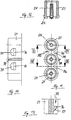
- FIGS. 5 to 10 Three plugs 1, similar to those shown in Figure 1, can be made using one they overlap common locking device 10 to a triple connector can be summarized as shown in Figure 5. Details of a such locking device 10 result from FIGS. 5 to 10.
- the locking device 10 has a frame which is approximately in plan view is rectangular and has two triple clips 31 on its two long sides and 32, which receive the three connectors 1 in parallel next to each other.
- the connector 1 is engaged with its annular groove 9 or clipped into the other triple clamp 32 which is attached to the connector housing subsequent crimp sleeve 3 or the coaxial cable emerging therefrom snapped in or clipped in.
- the locking device 10 holds the three Plug 1 in this way into a manageable unit.
- the Locking device 10 is also in this embodiment as a detent spring trained and for this purpose has two fingers 12 and 13, which are parallel run to each other and from that leg of the frame of the locking device 10 go out, which forms the back of the triple bracket 31.
- the levers 18 used to operate the two fingers 12 and 13 are through a web 33 connected to each other so that the two fingers 12 and 13 through Pressure on the web 33 can be operated together.
- the web 33 is in the Area of a window 34 provided in the frame.
- the associated couplers 21 are - as shown in Figures 11 to 14 - to a triple coupler with an integrally cast outer conductor.
- On one side of the triple coupler are in the gussets 35, which exist between adjacent couplers 21, projections 36, which however are not so high that they protrude from the gussets 35.
- the projections 36 have inclined surfaces 37 on which the fingers 12 and 13 when plugging together the connector 1 with the couplers 21 slide on until they protrude 16 snap behind the projections 36 and a positive lock cause.
- the outer conductor of the triple coupler is preferably made of die cast.
- Of the middle coupler 21 is on the outer conductor with a longitudinal rib 38 provided which serves as a carrier for coding.
Landscapes
- Coupling Device And Connection With Printed Circuit (AREA)
- Details Of Connecting Devices For Male And Female Coupling (AREA)
Abstract
Description
- Figur 1
- zeigt einen erfindungsgemäßen Stecker halb in einer Seitenansicht und halb im Längsschnitt,
- Figur 2
- zeigt einen zu dem Stecker in Figur 1 passenden Kuppler halb in einer Seitenansicht und halb in einem Längsschnitt,
- Figur 3
- zeigt den in Figur 1 und Figur 2 dargestellten Steckverbinder zusammengesteckt in einer Seitenansicht, an einer Gehäusewand angebracht,
- Figur 4
- zeigt den in den Figuren 1 und 2 dargestellten Steckverbinder zusammengesteckt in einer Seitenansicht, wobei der Kuppler zurückgesetzt in einer Vertiefung einer Gehäusewand angeordnet ist,
- Figur 5
- zeigt eine Rastfeder mit Dreifachklammern zur Aufnahme von drei Steckern,
- Figur 6
- zeigt die Rastfeder aus Figur 5 in einer Ansicht auf ihre Unterseite,
- Figur 7
- zeigt den Schnitt VII-VII gemäß Figur 6,
- Figur 8
- zeigt den Schnitt VIII-VIII gemäß Figur 6,
- Figur 9
- zeigt die Ansicht der Rastfeder in Blickrichtung des Pfeil IX in Figur 6,
- Figur 10
- zeigt die Ansicht der Rastfeder in Blickrichtung des Pfeils X in Figur 6,
- Figur 11
- zeigt einen koaxialen Dreifach-Kuppler in einer Vorderansicht, passend zu der Gruppe von Steckern in Figur 5,
- Figur 12
- zeigt den Schnitt XII-XII gemäß Figur 11,
- Figur 13
- zeigt den Schnitt XIII-XIII gemäß Figur 11, und
- Figur 14
- zeigt die Draufsicht mit Blickrichtung gemäß Pfeil 14 auf den Dreifach-Kuppler gemäß Figur 11.
Claims (21)
- Koaxialer Steckverbinder mit Schnappverriegelung für die Kommunikationstechnik, insbesondere in Fahrzeugen,dadurch gekennzeichnet, daß die Verriegelungseinrichtung (10) eine Rastfeder ist, welche an einer Stelle (9) in der Nähe der Isolierstütze (8) auf dem Gehäuse (2) des Steckers (1) angebracht ist, sich mit mindestens einem Finger (12, 13) an der Hülse (5) entlang erstreckt und an der Spitze des Fingers (12, 13) einen gegen die Steckachse (14) gerichteten Vorsprung (16) hat,bestehend aus einem Stecker (1) mit einem den Außenleiter des Steckers bildenden, einstückigen Gehäuse (2), welches mittels einer Isolierstütze (8) einen den Innenleiter des Steckers bildenden Kontakt (6) hält und hinter der Isolierstütze (8) einen hinteren Teil (3) zur Befestigung auf dem Mantel eines koaxialen Kabels (4) sowie vor der Isolierstütze (8) eine den Kontakt (6) koaxial umgebende Hülse (5) aufweist und außen eine Verriegelungseinrichtung (10) trägt,und aus einem Kuppler (21) mit Außenleiter und mit einer koaxial darin angeordneten und durch eine Isolierstütze (23) gehaltenen, den Innenleiter des Kupplers (21) bildenden Gegenkontakt (25) sowie mit Verriegelungsmitteln (27) auf der Außenseite des Kupplers (21),wobei nach der in Richtung einer Steckachse (14) erfolgten Steckverbindung einerseits die Hülse (5) des Steckers (1) und der Außenleiter des Kupplers (21) und andererseits die Verriegelungseinrichtung (10) und die Verriegelungsmittel (27) ineinandergreifen und hinsichtlich des Innenleiters der Kontakt (6) und der Gegenkontakt (25) in gegenseitigem Eingriff stehen,daß die Finger (12, 13) über jene Stelle (9) hinaus nach hinten verlängert sind zur Bildung von Hebeln (18, 19), welche in Richtung gegen den hinteren Teil (3) des Gehäuses (2) gedrückt werden können, wodurch die Finger (12, 13) elastisch nach außen schwenken,daß die Verriegelungsmittel (27) an dem Kuppler (21) durch einen äußeren Vorsprung oder durch einen Einschnitt gebildet sind, hinter welchen bzw. in welchen die Finger (12, 13) mit ihrem Vorsprung (16) einrasten,und daß die Rastfeder (10) einen Ring (11) hat, mit welchem sie auf der Außenseite des Steckgehäuses (2) festgelegt ist und von welchem einerseits die Finger (12, 13) und andererseits die Hebel (18, 19) zu ihrer Betätigung ausgehen.
- Koaxialer Steckverbinder mit Schnappverriegelung für die Kommunikationstechnik, insbesondere in Fahrzeugen,dadurch gekennzeichnet, daß die Verriegelungseinrichtung (10) eine Rastfeder ist, welche an einer Stelle (9) in der Nähe der Isolierstütze (8) auf dem Gehäuse (2) des Steckers (1) angebracht ist, sich mit mindestens einem Finger (12, 13) an der Hülse (5) entlang erstreckt und an der Spitze des Fingers (12, 13) einen gegen die Steckachse (14) gerichteten Vorsprung (16) hat,bestehend aus einem Stecker (1) mit einem den Außenleiter des Steckers bildenden, einstückigen Gehäuse (2), welches mittels einer Isolierstütze (8) einen den Innenleiter des Steckers bildenden Kontakt (6) hält und hinter der Isolierstütze (8) einen hinteren Teil (3) zur Befestigung auf dem Mantel eines koaxialen Kabels (4) sowie vor der Isolierstütze (8) eine den Kontakt (6) koaxial umgebende Hülse (5) aufweist und außen eine Verriegelungseinrichtung (10) trägt,und aus einem Kuppler (21) mit Außenleiter und mit einer koaxial darin angeordneten und durch eine Isolierstütze (23) gehaltenen, den Innenleiter des Kupplers (21) bildenden Gegenkontakt (25) sowie mit Verriegelungsmitteln (27) auf der Außenseite des Kupplers (21),wobei nach der in Richtung einer Steckachse (14) erfolgten Steckverbindung einerseits die Hülse (5) des Steckers (1) und der Außenleiter des Kupplers (21) und andererseits die Verriegelungseinrichtung (10) und die Verriegelungsmittel (27) ineinandergreifen und hinsichtlich des Innenleiters der Kontakt (6) und der Gegenkontakt (25) in gegenseitigem Eingriff stehen,daß die Finger (12, 13) über jene Stelle (9) hinaus nach hinten verlängert sind zur Bildung von Hebeln (18, 19), welche in Richtung gegen den hinteren Teil (3) des Gehäuses (2) gedrückt werden können, wodurch die Finger (12, 13) elastisch nach außen schwenken,daß die Verriegelungsmittel (27) an dem Kuppler (21) durch einen äußeren Vorsprung oder durch einen Einschnitt gebildet sind, hinter welchen bzw. in welchen die Finger (12, 13) mit ihrem Vorsprung (16) einrasten,und daß die Rastfeder (10) eine Klammer (31, 32) hat, mit welcher sie auf der Außenseite des Steckergehäuses (2) festgelegt ist.
- Steckverbinder nach Anspruch 1 oder 2, dadurch gekennzeichnet, daß die Hülse (5) des Steckers (1) den Außenleiter des Kupplers (2) aufnimmt.
- Steckverbinder nach Anspruch 3, dadurch gekennzeichnet, daß die Verriegelungsmittel (27) an dem Kuppler (21) durch einen Bund gebildet sind.
- Steckverbinder nach Anspruch 4, dadurch gekennzeichnet, daß die Rastfeder (10) in einer auf der Außenseite des Steckergehäuses (2) vorgesehenen Ringnut (9) festgelegt ist.
- Steckverbinder nach einem der vorstehenden Ansprüche, dadurch gekennzeichnet, daß genau zwei Finger (12, 13) und zwei Hebel (18, 19) vorgesehen sind und diese einander paarweise diametral gegenüberliegen.
- Steckverbinder nach Anspruch 2, dadurch gekennzeichnet, daß die Kammer (31, 32) als Mehrfachklammer ausgebildet ist zur Aufnahme mehrerer Steckergehäuse (2) nebeneinander.
- Steckverbinder nach Anspruch 7, dadurch gekennzeichnet, daß die Klammer (31, 32) Bestandteil eines die Gesamtheit der Steckergehäuse (2) umgreifenden Rahmens (Figur 5) oder einer Halbschale ist.
- Steckverbinder nach Anspruch 8, dadurch gekennzeichnet, daß am Rahmen (Figur 5) bzw. an der Halbschale zwei in Richtung der Längsachse (14) des Steckverbinders einen Abstand aufweisende Klammem bzw. Mehrfachklammern (31, 32) vorgesehen sind.
- Steckverbinder nach einem der Ansprüche 7 bis 9, dadurch gekennzeichnet, daß mehrere Finger (12, 13) nebeneinander vorgesehen sind, welche einen gemeinsamen Hebel (18) zu ihrer Betätigung haben.
- Steckverbinder nach einem der Ansprüche 7 bis 10, dadurch gekennzeichnet, daß die Finger (12, 13) in Bezug auf die Mehrfachklammern (31, 32) so angeordnet sind, daß sie in zwickelförmigen Lücken zwischen benachbarten Steckergehäusen (2) liegen,
und daß mehrere Kuppler (21) zu einer Baueinheit zusammengefaßt sind, bei welcher in den Zwickeln zwischen den Kupplern (21) die Vorsprünge (27) liegen, hinter denen die Finger (12, 13) einrasten. - Steckverbinder nach Anspruch 11, dadurch gekennzeichnet, daß die Kuppler (21) die Hülsen (5) der Stecker (1) aufnehmen.
- Steckverbinder nach einem der vorstehenden Ansprüche, dadurch gekennzeichnet, daß die Rastfeder (10) aus Kunststoff besteht.
- Steckverbinder nach einem der vorstehenden Ansprüche, dadurch gekennzeichnet, daß der hintere Teil (3) des Gehäuses (2) des Steckers (1) als Crimphülse ausgebildet ist.
- Steckverbinder nach einem der vorstehenden Ansprüche, dadurch gekennzeichnet, daß der Kontaktstift (6) des Steckers (1) in seinem hinteren Abschnitt als Crimphülse ausgebildet ist.
- Steckverbinder nach einem der vorstehenden Ansprüche, dadurch gekennzeich-net, daß die Hülse (5) und/oder der Kuppler (21) radial federnd ausgebildet sind.
- Steckverbinder nach einem der vorstehenden Ansprüche, dadurch gekennzeichnet, daß der Kontakt (6) ein hohler Kontaktstift und der Gegenkontakt (25) eine längs geschlitzte Kontaktbuchse ist.
- Steckverbinder nach einem der vorstehenden Ansprüche, dadurch gekennzeichnet, daß der Kuppler (21) eine Buchse mit starrem Außenleiter ist.
- Steckverbinder nach einem der vorstehenden Ansprüche, dadurch gekennzeichnet, daß der Außenleiter des Kupplers (21) die Hülse (5) des Steckers (1) aufnimmt und die Finger (12, 13) sich höchstens bis zum vorderen Ende der Hülse (5) des Steckers (1) erstrecken.
- Steckverbinder nach einem der Ansprüche 1 bis 18, dadurch gekennzeichnet, daß die Hülse (5) des Steckers (1) den Außenleiter des Kupplers (21) aufnimmt und sich die Finger (12, 13) bis über den vorderen Rand der Hülse (5) des Steckers (1) hinaus erstrecken.
- Koaxialer Stecker (1) nach einem der vorstehenden Ansprüchen zur Verwendung in einem Steckverbinder mit den in einem der vorstehenden Ansprüche enthaltenen Merkmalen.
Applications Claiming Priority (5)
| Application Number | Priority Date | Filing Date | Title |
|---|---|---|---|
| DE19543281 | 1995-11-20 | ||
| DE19543281 | 1995-11-20 | ||
| DE19609571A DE19609571A1 (de) | 1995-11-20 | 1996-03-12 | Koaxialer Steckverbinder für die Kommunikationstechnik in Automobilen |
| DE19609571 | 1996-03-12 | ||
| PCT/EP1996/005119 WO1997019496A1 (de) | 1995-11-20 | 1996-11-20 | Koaxialer steckverbinder für die kommunikationstechnik insbesondere in fahrzeugen |
Publications (2)
| Publication Number | Publication Date |
|---|---|
| EP0867054A1 EP0867054A1 (de) | 1998-09-30 |
| EP0867054B1 true EP0867054B1 (de) | 1999-08-18 |
Family
ID=26020527
Family Applications (1)
| Application Number | Title | Priority Date | Filing Date |
|---|---|---|---|
| EP96939106A Expired - Lifetime EP0867054B1 (de) | 1995-11-20 | 1996-11-20 | Koaxialer steckverbinder für die kommunikationstechnik insbesondere in fahrzeugen |
Country Status (4)
| Country | Link |
|---|---|
| US (1) | US6132234A (de) |
| EP (1) | EP0867054B1 (de) |
| ES (1) | ES2138386T3 (de) |
| WO (1) | WO1997019496A1 (de) |
Families Citing this family (46)
| Publication number | Priority date | Publication date | Assignee | Title |
|---|---|---|---|---|
| DE19849140C1 (de) * | 1998-10-23 | 2000-03-30 | Sihn Jr Kg Wilhelm | Codierungssystem für Steckverbinder |
| DE10012387C2 (de) * | 2000-03-14 | 2002-10-02 | Itt Mfg Enterprises Inc | Anordnung zum Verbinden eines Kabels mit einem Kraftfahrzeugbatteriepol |
| US6681458B2 (en) * | 2001-08-02 | 2004-01-27 | International Engine Intellectual Property Company, Llc | Spring clip |
| TW511801U (en) * | 2001-08-31 | 2002-11-21 | Hon Hai Prec Ind Co Ltd | Cable connector assembly |
| US6585536B1 (en) * | 2002-09-11 | 2003-07-01 | Hon Hai Precision Ind. Co., Ltd. | Cable end connector with locking member |
| US6585537B1 (en) * | 2002-10-24 | 2003-07-01 | Hon Hai Precision Ind. Co., Ltd. | Cable end connector with locking member |
| TW549667U (en) * | 2002-12-04 | 2003-08-21 | Hon Hai Prec Ind Co Ltd | Radio frequency connector assembly |
| CN100481630C (zh) * | 2003-02-21 | 2009-04-22 | Eta瑞士钟表制造股份有限公司 | 用于在便携式电子仪器和外部设备之间建立电连接、尤其用于对所述仪器的电池进行再充电的装置 |
| KR200322064Y1 (ko) * | 2003-05-19 | 2003-08-06 | 한국몰렉스 주식회사 | 케이블 접속용 커넥터 |
| DE202004007909U1 (de) * | 2004-05-17 | 2004-07-22 | Rosenberger Hochfrequenztechnik Gmbh & Co | Gehäusekuppler für einen Koaxialsteckverbinder |
| US7114990B2 (en) | 2005-01-25 | 2006-10-03 | Corning Gilbert Incorporated | Coaxial cable connector with grounding member |
| US7189097B2 (en) * | 2005-02-11 | 2007-03-13 | Winchester Electronics Corporation | Snap lock connector |
| US7322851B2 (en) * | 2006-01-27 | 2008-01-29 | Jeffrey Brookmire | Coaxial cable connector |
| US20080060922A1 (en) * | 2006-09-11 | 2008-03-13 | Benson Su | Modularized push button switch |
| FR2922053B1 (fr) * | 2007-10-08 | 2012-09-07 | Zedel | Dispositif de raccordement electrique entre un recepteur portatif et une source d'energie |
| US20100087086A1 (en) * | 2008-10-06 | 2010-04-08 | Acterna Llc | Female Quick Connect Clip For Coaxial Cable |
| EP2190078A1 (de) * | 2008-11-25 | 2010-05-26 | Mark Godovich | Techniken zum Schutz eines benutzerzugänglichen elektrischen Steckverbinders |
| US20100304579A1 (en) * | 2009-05-26 | 2010-12-02 | Brian Lyle Kisling | Low Resistance Connector For Printed Circuit Board |
| TWI549386B (zh) | 2010-04-13 | 2016-09-11 | 康寧吉伯特公司 | 具有防止進入及改良接地之同軸連接器 |
| BR112012029627B1 (pt) * | 2010-05-21 | 2020-11-10 | Cooper Technologies Company | adaptador e método para acoplamento em conjunto |
| US8888526B2 (en) | 2010-08-10 | 2014-11-18 | Corning Gilbert, Inc. | Coaxial cable connector with radio frequency interference and grounding shield |
| TWI558022B (zh) * | 2010-10-27 | 2016-11-11 | 康寧吉伯特公司 | 具有耦合器和固持及釋放機制的推入固定式纜線連接器 |
| MY191954A (en) * | 2011-03-28 | 2022-07-20 | Fishman Corp | System and method for releasably coupling a fluid dispenser to a dispensing system |
| US9190744B2 (en) | 2011-09-14 | 2015-11-17 | Corning Optical Communications Rf Llc | Coaxial cable connector with radio frequency interference and grounding shield |
| US20130072057A1 (en) | 2011-09-15 | 2013-03-21 | Donald Andrew Burris | Coaxial cable connector with integral radio frequency interference and grounding shield |
| US9136654B2 (en) | 2012-01-05 | 2015-09-15 | Corning Gilbert, Inc. | Quick mount connector for a coaxial cable |
| US9407016B2 (en) | 2012-02-22 | 2016-08-02 | Corning Optical Communications Rf Llc | Coaxial cable connector with integral continuity contacting portion |
| US9287659B2 (en) | 2012-10-16 | 2016-03-15 | Corning Optical Communications Rf Llc | Coaxial cable connector with integral RFI protection |
| US9147963B2 (en) | 2012-11-29 | 2015-09-29 | Corning Gilbert Inc. | Hardline coaxial connector with a locking ferrule |
| US9153911B2 (en) | 2013-02-19 | 2015-10-06 | Corning Gilbert Inc. | Coaxial cable continuity connector |
| US9172154B2 (en) | 2013-03-15 | 2015-10-27 | Corning Gilbert Inc. | Coaxial cable connector with integral RFI protection |
| US10290958B2 (en) | 2013-04-29 | 2019-05-14 | Corning Optical Communications Rf Llc | Coaxial cable connector with integral RFI protection and biasing ring |
| EP3000154B1 (de) | 2013-05-20 | 2019-05-01 | Corning Optical Communications RF LLC | Koaxialkabelverbinder mit integralem rfi-schutz |
| US9548557B2 (en) | 2013-06-26 | 2017-01-17 | Corning Optical Communications LLC | Connector assemblies and methods of manufacture |
| US9048599B2 (en) | 2013-10-28 | 2015-06-02 | Corning Gilbert Inc. | Coaxial cable connector having a gripping member with a notch and disposed inside a shell |
| WO2016073309A1 (en) | 2014-11-03 | 2016-05-12 | Corning Optical Communications Rf Llc | Coaxial cable connector with integral rfi protection |
| US10033122B2 (en) | 2015-02-20 | 2018-07-24 | Corning Optical Communications Rf Llc | Cable or conduit connector with jacket retention feature |
| US9590287B2 (en) | 2015-02-20 | 2017-03-07 | Corning Optical Communications Rf Llc | Surge protected coaxial termination |
| US10211547B2 (en) | 2015-09-03 | 2019-02-19 | Corning Optical Communications Rf Llc | Coaxial cable connector |
| US9525220B1 (en) | 2015-11-25 | 2016-12-20 | Corning Optical Communications LLC | Coaxial cable connector |
| CN105977723A (zh) * | 2016-07-29 | 2016-09-28 | 中航光电科技股份有限公司 | 一种连接器及使用该连接器的连接器组件 |
| CN109286100B (zh) * | 2017-07-21 | 2021-06-04 | 泰科电子(上海)有限公司 | 电连接器 |
| DE102017128604A1 (de) * | 2017-12-01 | 2019-06-06 | Neutrik Ag | Elektrische Steckverbindung zur Datenübertragung |
| CN110277705B (zh) * | 2019-07-05 | 2020-12-22 | 上海航天科工电器研究院有限公司 | 一种高容错性射频同轴连接器及组件 |
| EP3767750B1 (de) * | 2019-07-16 | 2022-03-02 | Rosenberger Hochfrequenztechnik GmbH & Co. KG | Elektrischer steckverbinder, isolierschutzelement und verfahren zur montage eines elektrischen steckverbinders |
| US12034264B2 (en) | 2021-03-31 | 2024-07-09 | Corning Optical Communications Rf Llc | Coaxial cable connector assemblies with outer conductor engagement features and methods for using the same |
Family Cites Families (11)
| Publication number | Priority date | Publication date | Assignee | Title |
|---|---|---|---|---|
| US1552346A (en) * | 1924-12-27 | 1925-09-01 | Walter A Riley | Electric coupling |
| US3544951A (en) * | 1968-06-28 | 1970-12-01 | Deutsch Co Elec Comp | Coupling with deflectable arms |
| US3694793A (en) * | 1969-08-18 | 1972-09-26 | Itt | Snap lock coaxial connector |
| US4376563A (en) * | 1981-03-20 | 1983-03-15 | General Motors Corporation | Electrical connector with mechanically assisted latch means |
| GB8403412D0 (en) * | 1984-02-09 | 1984-03-14 | Lucas Ind Plc | Electrical connectors |
| US4697859A (en) * | 1986-08-15 | 1987-10-06 | Amp Incorporated | Floating coaxial connector |
| US4801275A (en) * | 1987-11-30 | 1989-01-31 | Yazaki Corporation | Connector lock device |
| DE3740580A1 (de) * | 1987-11-30 | 1989-06-08 | Grote & Hartmann | Elektrischer steckverbinder |
| DE4100112C1 (en) * | 1991-01-04 | 1991-12-19 | Kabelwerke Reinshagen Gmbh, 5600 Wuppertal, De | Plug connector with two-arm lever locking arrangement - has engaging plate arranged at angle of 30 to 90 deg. w.r.t. direction of insertion |
| FR2715512A1 (fr) * | 1994-01-24 | 1995-07-28 | Pizon Ernest | Connecteur pour câble coaxial. |
| US5727963A (en) * | 1996-05-01 | 1998-03-17 | Lemaster; Dolan M. | Modular power connector assembly |
-
1996
- 1996-11-20 US US09/077,178 patent/US6132234A/en not_active Expired - Lifetime
- 1996-11-20 EP EP96939106A patent/EP0867054B1/de not_active Expired - Lifetime
- 1996-11-20 ES ES96939106T patent/ES2138386T3/es not_active Expired - Lifetime
- 1996-11-20 WO PCT/EP1996/005119 patent/WO1997019496A1/de not_active Ceased
Also Published As
| Publication number | Publication date |
|---|---|
| EP0867054A1 (de) | 1998-09-30 |
| WO1997019496A1 (de) | 1997-05-29 |
| US6132234A (en) | 2000-10-17 |
| ES2138386T3 (es) | 2000-01-01 |
Similar Documents
| Publication | Publication Date | Title |
|---|---|---|
| EP0867054A1 (de) | Koaxialer steckverbinder für die kommunikationstechnik insbesondere in fahrzeugen | |
| DE19609571A1 (de) | Koaxialer Steckverbinder für die Kommunikationstechnik in Automobilen | |
| DE602004011002T2 (de) | Wasserdichter Verbinder und Zusammenbauverfahren | |
| DE19500959C2 (de) | Elektrischer Steckverbinder | |
| EP1641085B1 (de) | Verriegelung für eine Steckverbindung | |
| DE3779702T2 (de) | In einer flachbaugruppe montierte dreiachsige steckverbindereinrichtung. | |
| DE69602306T2 (de) | Elektrischer Verbinder | |
| DE60001437T2 (de) | Elektrische Verbinderanordnung mit Abschirmung zur unmittelbaren Befestigung an Geräte | |
| EP0772261A2 (de) | Koaxial-Steckverbindung | |
| DE69809505T2 (de) | Verbindungsanordnung eines Verbinders | |
| DE19938068A1 (de) | Leistungsverteilungszentrum mit verbesserter Leistungsversorgungsverbindung | |
| DE102016120063A1 (de) | Steckverbindung | |
| DE69416079T2 (de) | Klemmverbinder | |
| EP3399599B1 (de) | Steckverbinder, stecker und steckverbindersystem | |
| DE7915035U1 (de) | Elektrische Anschlußvorrichtung | |
| DE19848289C2 (de) | Verriegelungsvorrichtung eines Kappenteils | |
| EP3782235A1 (de) | Direktsteckverbinder | |
| EP1671399B1 (de) | Schirmanbindung | |
| DE10159195C2 (de) | Verbinder und Verfahren zum Zusammenbauen eines Verbinders | |
| EP1154521B1 (de) | Steckverbinder und Verfahren zur Montage eines Steckverbinders | |
| DE4300759C2 (de) | Lampenfassung | |
| DE4410072A1 (de) | Koaxialkabel-Steckverbinderanordnung | |
| EP1720222B1 (de) | Steckverbinder, insbesondere für Airbag-Zündsysteme | |
| DE29521491U1 (de) | Elektrischer Steckverbinder | |
| DE19525801C2 (de) | Vorrichtung zum elektrisch leitenden Verbinden von zwei elektrischen Leitungen |
Legal Events
| Date | Code | Title | Description |
|---|---|---|---|
| PUAI | Public reference made under article 153(3) epc to a published international application that has entered the european phase |
Free format text: ORIGINAL CODE: 0009012 |
|
| 17P | Request for examination filed |
Effective date: 19980619 |
|
| AK | Designated contracting states |
Kind code of ref document: A1 Designated state(s): DE ES FR GB IT SE |
|
| GRAG | Despatch of communication of intention to grant |
Free format text: ORIGINAL CODE: EPIDOS AGRA |
|
| 17Q | First examination report despatched |
Effective date: 19981127 |
|
| GRAG | Despatch of communication of intention to grant |
Free format text: ORIGINAL CODE: EPIDOS AGRA |
|
| GRAH | Despatch of communication of intention to grant a patent |
Free format text: ORIGINAL CODE: EPIDOS IGRA |
|
| GRAH | Despatch of communication of intention to grant a patent |
Free format text: ORIGINAL CODE: EPIDOS IGRA |
|
| GRAA | (expected) grant |
Free format text: ORIGINAL CODE: 0009210 |
|
| AK | Designated contracting states |
Kind code of ref document: B1 Designated state(s): DE ES FR GB IT SE |
|
| REF | Corresponds to: |
Ref document number: 59602828 Country of ref document: DE Date of ref document: 19990923 |
|
| ITF | It: translation for a ep patent filed | ||
| GBT | Gb: translation of ep patent filed (gb section 77(6)(a)/1977) |
Effective date: 19991118 |
|
| ET | Fr: translation filed | ||
| REG | Reference to a national code |
Ref country code: ES Ref legal event code: FG2A Ref document number: 2138386 Country of ref document: ES Kind code of ref document: T3 |
|
| PLBE | No opposition filed within time limit |
Free format text: ORIGINAL CODE: 0009261 |
|
| STAA | Information on the status of an ep patent application or granted ep patent |
Free format text: STATUS: NO OPPOSITION FILED WITHIN TIME LIMIT |
|
| 26N | No opposition filed | ||
| REG | Reference to a national code |
Ref country code: GB Ref legal event code: IF02 |
|
| PGFP | Annual fee paid to national office [announced via postgrant information from national office to epo] |
Ref country code: DE Payment date: 20100927 Year of fee payment: 15 |
|
| PGFP | Annual fee paid to national office [announced via postgrant information from national office to epo] |
Ref country code: GB Payment date: 20101123 Year of fee payment: 15 Ref country code: IT Payment date: 20101126 Year of fee payment: 15 |
|
| PGFP | Annual fee paid to national office [announced via postgrant information from national office to epo] |
Ref country code: SE Payment date: 20111122 Year of fee payment: 16 Ref country code: ES Payment date: 20111123 Year of fee payment: 16 Ref country code: FR Payment date: 20111125 Year of fee payment: 16 |
|
| GBPC | Gb: european patent ceased through non-payment of renewal fee |
Effective date: 20121120 |
|
| PG25 | Lapsed in a contracting state [announced via postgrant information from national office to epo] |
Ref country code: SE Free format text: LAPSE BECAUSE OF NON-PAYMENT OF DUE FEES Effective date: 20121121 |
|
| REG | Reference to a national code |
Ref country code: FR Ref legal event code: ST Effective date: 20130731 |
|
| PG25 | Lapsed in a contracting state [announced via postgrant information from national office to epo] |
Ref country code: IT Free format text: LAPSE BECAUSE OF NON-PAYMENT OF DUE FEES Effective date: 20121120 |
|
| REG | Reference to a national code |
Ref country code: DE Ref legal event code: R119 Ref document number: 59602828 Country of ref document: DE Effective date: 20130601 |
|
| PG25 | Lapsed in a contracting state [announced via postgrant information from national office to epo] |
Ref country code: DE Free format text: LAPSE BECAUSE OF NON-PAYMENT OF DUE FEES Effective date: 20130601 |
|
| PG25 | Lapsed in a contracting state [announced via postgrant information from national office to epo] |
Ref country code: FR Free format text: LAPSE BECAUSE OF NON-PAYMENT OF DUE FEES Effective date: 20121130 Ref country code: GB Free format text: LAPSE BECAUSE OF NON-PAYMENT OF DUE FEES Effective date: 20121120 |
|
| REG | Reference to a national code |
Ref country code: ES Ref legal event code: FD2A Effective date: 20140304 |
|
| PG25 | Lapsed in a contracting state [announced via postgrant information from national office to epo] |
Ref country code: ES Free format text: LAPSE BECAUSE OF NON-PAYMENT OF DUE FEES Effective date: 20121121 |