EP0866311A2 - Méthode pour afficher de l'information directionnelle d'un système de navigation - Google Patents
Méthode pour afficher de l'information directionnelle d'un système de navigation Download PDFInfo
- Publication number
- EP0866311A2 EP0866311A2 EP98200726A EP98200726A EP0866311A2 EP 0866311 A2 EP0866311 A2 EP 0866311A2 EP 98200726 A EP98200726 A EP 98200726A EP 98200726 A EP98200726 A EP 98200726A EP 0866311 A2 EP0866311 A2 EP 0866311A2
- Authority
- EP
- European Patent Office
- Prior art keywords
- distance
- directional
- vehicle position
- vehicle
- route
- Prior art date
- Legal status (The legal status is an assumption and is not a legal conclusion. Google has not performed a legal analysis and makes no representation as to the accuracy of the status listed.)
- Granted
Links
Images

Classifications
-
- G—PHYSICS
- G01—MEASURING; TESTING
- G01C—MEASURING DISTANCES, LEVELS OR BEARINGS; SURVEYING; NAVIGATION; GYROSCOPIC INSTRUMENTS; PHOTOGRAMMETRY OR VIDEOGRAMMETRY
- G01C21/00—Navigation; Navigational instruments not provided for in groups G01C1/00 - G01C19/00
- G01C21/26—Navigation; Navigational instruments not provided for in groups G01C1/00 - G01C19/00 specially adapted for navigation in a road network
- G01C21/34—Route searching; Route guidance
- G01C21/36—Input/output arrangements for on-board computers
- G01C21/3626—Details of the output of route guidance instructions
- G01C21/3632—Guidance using simplified or iconic instructions, e.g. using arrows
Definitions
- Such a method for output of directional information as well as a Such a navigation system is known for example from EP 534 533 A1.
- the direction information is in the form of abstracted intersection displays.
- the display of the abstracted Intersection representations are particularly suitable for fully digitized areas, i.e. for areas in which every single street of this area in the map memory of the Navigation system is saved. This is especially true for larger cities. Smaller cities and rural areas are in the map memory of the However, the navigation system is often only partially digitized, i.e. Not every street in this area is recorded in the memory of the navigation system. On Crossroads or road junctions that are not from the store of the Navigation system are detected, it can therefore be one with a driver vehicle equipped with such a navigation system for basic clarifications or Misunderstandings arise regarding the route to be traveled.
- a map of the surroundings can be shown in the abstracted intersection display is provided in particular for orientation in partially digitized areas.
- To one To be able to represent such a map of the area satisfactorily is a high resolution screen required.
- This object is achieved for a method in that a first Direction indicator to show the direct direction from a current one Vehicle position to a lying on the route by a distance a distance point is provided along the planned route, the Distance point is continuously adjusted depending on the vehicle position.
- the first direction indicator is used to show the planned direction in the close surroundings of the current vehicle position.
- the direct Direction i.e. the direction along the straight line from the current one Vehicle position to a distance point on the route is displayed.
- the distance point is in the direction of travel before the current vehicle position and is a respective distance traveled, i.e. the route along the planned Road or route, from the current vehicle position. During the journey, the distance point becomes the vehicle's position changes moved and thus adapted to the vehicle position.
- the distance point is preferably on the order of approximately 50 m to approx. 500 m along the planned route from the current vehicle position away.
- the first directional display enables particularly in partially digitized areas a constant, continuous display of those planned in the immediate vicinity Direction of travel. In case of doubtful crossings, the user can see the Recognize the planned direction and continue the journey in the right direction.
- the first direction indicator enables the driver to continuously Directional information, even if there is no active information. e.g. that he was at one Turn should be present.
- the first direction display can be very easily e.g. in the form of a straight line Represent arrow or in the form of a compass needle.
- the first Direction indication also on simple displays or screens, e.g. on Realize monochrome screens.
- a variation of the distance traveled enables the distance traveled to be displayed various parameters, e.g. Vehicle parameters, environmental parameters and Road parameters, adjust and thereby the first directional display for the Optimize users.
- a further advantageous embodiment of the invention is characterized by the Features of claim 4.
- the type of roadway is understood to mean the respective classification under which the individual streets in the map memory of the navigation system are classified.
- Classification types are e.g. Motorways, federal highways, state roads, Side streets and the like are provided.
- the higher the expected Average speed on the respective lane type is the greater advantageously selected the distance traveled for this type of road. So is for example, a high average speed can be expected on motorways. and the course of a freeway usually shows few curves on. It is therefore advantageous to have a long distance for highways to provide. In contrast, there is a smaller one on a small side street Average speed and a significantly more curvy course of the Lane expected. Therefore, it is advantageous for the road type of secondary road to provide a shorter distance.
- it is advantageous for individual lane types of the navigation system stored in the map memory to provide a guideline for the distance traveled and this depending to change the vehicle speed.
- the optimal value of the distance traveled is strongly dependent on the course of the road dependent. By changing the distance depending on the road surface this and thus the respective direction indicator for the respective lane course be optimized. In the case of special curve geometries in particular, it makes sense to use the Distance distance to choose relatively small. This can be done through a automatic adaptation of the distance traveled depending on the Lane course can be realized.
- Another option is to change the course of the road between the evaluate the current vehicle position and the current distance point. For this purpose it is provided on the distance between the current one Vehicle position and the current distance point in each case in equidistant Distances to set sub-distance points and to these sub-distance points respective angle of the first directional display with respect to the current one Calculate vehicle position. Exceeds the angular difference between them a predefined limit value for each calculated angle, it will automatically the distance traveled is reduced.
- predefinable intersection geometries to provide predeterminable distance routes.
- Intersection geometers are then passed through the respective Intersection of the predefinable distance routes for the first direction display used.
- the predeterminable intersection geometries can be recognized for example by means of a pattern recognition algorithm. It is also advantageous to vary the distance traveled depending on the To change the road surface.
- Another advantageous embodiment of the method according to the invention is characterized in that the distance traveled depending on the light and / or Visibility is changeable.
- the distance can be dipped or High beam range can be adjusted so that the distance point within the Visibility of the driver is. It is also possible to show the distance traveled other restrictions on visibility, e.g. in fog.
- the brightness sensors are e.g. Photo diodes can be used. It is also possible the switch for the low or high beam of the vehicle as a brightness sensor use, and depending on whether the high beam, the low beam or even no light is switched on, to set a predefinable distance.
- Such a combination of the first and the second direction indicator enables depending on the card information available optimal direction indicator.
- the software of the respective navigation system recognizes automatically whether the map information for the respective vehicle position in partially digitized or fully digitized form. Are the dates in partially digitized form, so the first directional display is preferably displayed, while in fully digitized environments the second direction indicator is provided. Sometimes it can also work in fully digitized environments to be advantageous, in addition to the abstract crossing representation, the first Direction display to be provided.
- Such a straight-ahead arrow signals to the user that the navigation system currently has no direction changes for him and that he should follow the current course of the road.
- unclear situations e.g. if in a non-digitized turn occurs on a sharp curve, the user can recognize how he should drive from the first direction indicator.
- the computing circuit uses the sensor signal to calculate the current one Position of the vehicle.
- a distance point is determined by the arithmetic circuit, which is one Distance traveled along the planned route in the direction of travel from current vehicle position is removed.
- the arithmetic circuit calculates as first direction information the direct direction, i.e. the direction along the Air line from the current vehicle position to the distance point.
- This first Direction information is sent from the arithmetic circuit to the output device supplied, which visually shows the first direction indicator.
- the arithmetic circuit is provided to vary the distance traveled.
- a variation of the distance traveled enables the distance traveled to be displayed various parameters, e.g. Vehicle parameters, environmental parameters and Road parameters, adjust and thereby the first directional display for the Optimize users.
- the optimal value of the distance traveled is strongly dependent on the course of the road dependent and can be carried out by a software in the arithmetic circuit automatic adjustment of the distance traveled can be set.
- a software in the arithmetic circuit automatic adjustment of the distance traveled can be set.
- a pattern recognition algorithm in the arithmetic circuit is implemented, which is automatically recognized when predeterminable Intersection geometries, e.g. in a memory of the navigation system distance journeys used.
- Another option is that the stored in a map storage unit of the navigation system Map information for predeterminable intersections or road courses as Additional information in each case for this intersection or this course of the road have optimal distance routes.
- a default value for the distance traveled can be specified by a user. With such a default value that can be entered by the user, anyone Adjust the first direction indicator to the driver's individual needs.
- Another advantageous embodiment of the navigation system is characterized by the feature of claim 9.
- Such a combination of the first and the second directional display makes it possible, depending on the map information available in the map storage unit of the navigation system, to offer the user an optimal directional display.
- the software of the arithmetic circuit automatically recognizes whether the card information supplied by the card storage unit for the respective vehicle position is available in partially digitized or fully digitized form. If the data is in partially digitized form, the computing circuit preferably delivers the first direction information to the output device, and the first direction indicator is displayed by the output device, while the second direction indicator is provided in fully digitized environments. In some cases, it can also be advantageous in fully digitized environments to display the first directional display in addition to the abstracted intersection by means of the output device.
- the first directional display can be displayed very easily, for example in the form of a straight arrow or in the form of a compass needle. Therefore, the first directional display can also be shown on screens with a low resolution, for example on monochrome screens with a resolution of 64x120 pixels. This enables very inexpensive navigation systems to be implemented.
- Such a display can be arranged in the driver's field of vision. Using such a display, the driver can quickly record the first directional information without having to take his eyes off the road.
- Fig. 1 shows a block diagram of an embodiment of an inventive Navigation system in which the method according to the invention is implemented.
- the navigation system shown in FIG. 1 has a central element Computing circuit 1, which with an operating device 2, a Card storage unit 3, an RDS / TMC receiver 4 and a GSM module 5 is coupled.
- the control device 2 can, for example, by means of a keyboard, a trackball or a touch-sensitive screen (touch screen) will be realized.
- the card storage unit 3 can, for example, by means of a CD-ROM drive can be realized, the card information on a or several CD-ROMs are stored.
- the RDS / TMC receiver 4 is used the reception of traffic information.
- both Traffic information that is transmitted according to the GSM standard is received be made as well as phone calls.
- An output device 6 which has an optical output module 7 and comprises an acoustic output module 8. Both the optical output module 7 and the acoustic output module 8 are also coupled to the computing circuit 1. It a sensor unit 9 is provided, the wheel sensors 10, an electronic one Compass 11 and a GPS receiver unit 12. The wheel sensors 10, the Compass 11 and the GPS receiving unit 12 are each with the arithmetic circuit 1st coupled. The wheel sensors 10 provide information from the left and the left right wheel of the vehicle, either from the front wheels or from the Rear wheels. The information of the wheel sensors, which they send to the computing circuit 1 transmitted affects both the distance traveled by the vehicle and Changes in direction due to different paths traveled by the left and the right wheel.
- the electronic compass 11 provides angle information to the arithmetic circuit 1.
- the GPS receiving unit 12 delivers Position information about the current position of the vehicle to the Arithmetic circuit 1. From the information in the card storage unit 3, the The wheel sensors 10, the compass 11 and the GPS receiver unit 12 calculate the Arithmetic circuit 1 the current position of the vehicle.
- the arithmetic circuit 1 delivers directional information to the depending on the current vehicle position Output device 6, the directional information optically and / or acoustically transmitted to the driver. It is possible to use the GPS receiver unit 12 to do without and the navigation system only with the map storage unit 3 To operate wheel sensors 10 and the compass 11.
- FIG. 2 shows a planned route 13 with a vehicle 15 located at a current vehicle position 14.
- a distance point 17 is located a distance 16 along the route 13 from the current vehicle position 14.
- Vehicle longitudinal direction arrow 18 extends from the current vehicle position 14 to the distance point 17.
- the vehicle longitudinal direction arrow 18 and the distance point direction arrow 19 extend to one another at a distance point direction angle ⁇ D.
- a first direction indicator 20 in the form of a compass needle 21 is assigned to this current vehicle position 14 and the associated distance point 17.
- This first directional display 20 is displayed on the optical output module 7 of the output device 6 according to FIG. 1.
- the compass needle 21 of the first direction indicator 20 is inclined by the distance point direction angle ⁇ D with respect to the vertical direction 22.
- the distance point direction angle ⁇ D is calculated by the arithmetic circuit 1 and supplied to the output device 6 as first direction information.
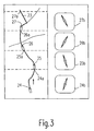
- FIG. 3 shows a route 23 with four different instantaneous routes Vehicle positions 24, 25, 26 and 27 and four of these vehicle positions assigned distance points 24a, 25a, 26a and 27a. To every one of these four current vehicle positions 24, 25, 26 and 27 is the associated first one Direction display 24b, 25b, 26b and 27b shown.
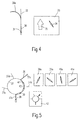
- FIG. 4 shows the course of a route 30 which has a sharp left curve 30a having.
- the vehicle is at the current vehicle position 31 the left turn 30a.
- a curve Secondary road 32 essentially straight ahead.
- This side street 32 is not digitized, i.e. 1 in the card storage unit 3 according to FIG Mauies 32 no information available, and accordingly can by the Card storage unit 3 according to FIG. 1 also has no information about it Secondary road 32 can be transmitted to the computing circuit 1 according to FIG. 1.
- the current vehicle position 31 is assigned a screen display 33 which is provided for display on the optical output module 7 according to FIG. 1.
- the screen display 33 has a first directional display 34 and, as a second directional display, a straight-ahead arrow 35.
- the straight-ahead arrow 35 signals to the driver that there are currently no indications of changes in direction of travel and that he should remain on the current road. Since the navigation system does not know the secondary road 32, there is no explicit acoustic signal in front of the left curve 32 that the driver should drive to the left. However, the driver can use the first direction indicator 34 to clarify that he should follow the left curve 30a and should not continue straight ahead along the non-digitized secondary road 32.
- FIG. 5 shows a planned route 36, which is at a circular intersection 37 with five branches 37a, 37b, 37c, 37d and 37e. 5 are four current vehicle positions 38, 39, 40 and 41 are shown. These four current vehicle positions 38, 39, 40 and 41 are the first Direction indicators 38a, 39a 40a and 41a assigned. In addition to the first Direction indicators 38a, 39a, 40a and 41a is a second direction indicator 42 provided, which is an abstract intersection of the circular Crossing 37 indicates. The planned route is on this second one Direction indicator 42 optically highlighted.
- the second direction indicator 42 changes not while driving through the circular intersection 37 and will statically displayed for all four current vehicle positions 38, 39, 40 and 41, while the first direction indicators 38a, 39a, 40a and 41a each follow according to the current vehicle position. If a user now approaches the circular intersection 37, he can himself first of all, an overview of what is going on using the second direction indicator 42 get him circular intersection 37 and the planned View route 36. If he then enters the circular intersection 37, he can preferably by means of the respectively current first direction indicator 38a, 39a, Orient 40a or 41a and find the right turn 37c.
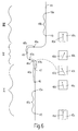
- FIG. 6 shows a planned route 44, which is initially in an area I runs straight, in an adjoining area II some curves and finally runs in a straight line again in an area III. Based This planned route 44 is a change in the course of the roadway Distance traveled explained.
- This current vehicle position 45 is a distance point 45a assigned to the distance 45b along the planned route 44 is from the current vehicle position 45.
- the current one Vehicle position 45 is a first direction indicator 45c with a vertical orientation Direction directional arrow 45d assigned.
- the distance 45b is a predefinable for the respective type of route 44 Distance normal value, e.g. in a memory of the computing unit 1 is saved. This distance distance normal value is then always for the Distance traveled distance used when the particular course of the road essentially is straightforward and the speed of the vehicle in a predetermined Speed range.
- the vehicle arrives at the current vehicle position 46, which is the distance traveled by the distance 46b Distance point 46a is assigned.
- the distance 46b is essentially the same as the distance 45b.
- the distance point 46a is at the beginning a left turn.
- the direction arrow 46d is that of the current one Vehicle direction 46 associated with first direction indicator 46c slightly to the left directed towards the vertical direction.
- the arithmetic circuit 1 recognizes this Angular deviation from the vertical direction and subsequently reduced automatically the distance traveled when the amount of angular deviation a predefinable limit value during a predefinable minimum travel distance exceeds. This can be seen from the current vehicle position 47, whose assigned distance point 47a by the distance 47b.
- the Distaliz route 47b is automatically reduced by the computing circuit 1 and only about half the distance 45b and 46b.
- the first directional display 47c associated with the current vehicle position 47 has a directional arrow 47d, which is about 45 ° with respect to the vertical is inclined.
- the driver can the curved course of the route 44 in the area II by means of the first Direction display can be displayed in a suitable manner. From the arithmetic circuit 1 is checked continuously or at discrete intervals whether the amounts of the Angular deviations from the vertical direction during the predeterminable The minimum travel distance is still above the specifiable limit. in the curved region II of route 44, this is the case, and accordingly the small value for the distance traveled is still used.
- This distance 48b corresponds essentially to that Distance distance 47b and is approximately half the distance distance distance 45b and 46b.
- the direction arrow 48d of the current vehicle position 48 assigned first direction indicator 48 is about 45 ° to the right compared to inclined in the vertical direction.
- the vehicle leaves the curved area II and arrives in the rectilinear area III, the computing circuit 1 recognizes 1 that the first directional display is again in the vertical direction sets and falls below the predefinable limit value for the angular deviation.
- the predefinable limit value for the angular deviation remains during the the specified minimum travel distance is undershot, then the distance traveled is again increased to the predeterminable normal value for the respective lane type. That's the way it is assigned the current vehicle position 49 to the distance point 49a, which by the Distance 49b from the current vehicle position 49 is removed.
- the Distance 49b corresponds to distance 45b and 46b.
- Direction indicator 49c points in the vertical direction.
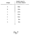
- Fig. 7 shows a table with seven different road types A to G, the a normal value for the distance traveled in meters is assigned.
- the Road types A to G are based on the expected average speed Classified and in each case in the card storage unit 3 according to FIG. 1 assigned stored streets.
- the lane type A represents motorways that Road type B federal roads, road type C well-developed country roads, the Road type D medium well-developed country roads, road type E poor upgraded country roads and F and G types of inner-city roads.
- the normal values for the respective road types A to G for the Distance routes are used advantageously if the current one Road is straight and the speed of the vehicle is within a predeterminable normal speed range.
- Driving the vehicle The computing circuit 1 according to FIG. 1 recognizes this faster on the basis of the Calculation circuit 1 supplied speed information, and the value for the distance traveled is continuous or gradual except for one Maximum value increased. If the vehicle has a speed below the Normal speed range, the distance will be continuous or reduced in steps to a predeterminable minimum value.
- the change of the road course dependent Normal values are provided for the distance traveled, as already shown in FIG. 6 described.
Landscapes
- Engineering & Computer Science (AREA)
- Radar, Positioning & Navigation (AREA)
- Remote Sensing (AREA)
- Automation & Control Theory (AREA)
- Physics & Mathematics (AREA)
- General Physics & Mathematics (AREA)
- Navigation (AREA)
- Traffic Control Systems (AREA)
Applications Claiming Priority (2)
| Application Number | Priority Date | Filing Date | Title |
|---|---|---|---|
| DE19711092 | 1997-03-17 | ||
| DE19711092A DE19711092A1 (de) | 1997-03-17 | 1997-03-17 | Navigationssystem und Verfahren zur Ausgabe von Richtunsinformationen des Navigationssystems |
Publications (3)
| Publication Number | Publication Date |
|---|---|
| EP0866311A2 true EP0866311A2 (fr) | 1998-09-23 |
| EP0866311A3 EP0866311A3 (fr) | 2000-04-05 |
| EP0866311B1 EP0866311B1 (fr) | 2005-08-10 |
Family
ID=7823680
Family Applications (1)
| Application Number | Title | Priority Date | Filing Date |
|---|---|---|---|
| EP98200726A Expired - Lifetime EP0866311B1 (fr) | 1997-03-17 | 1998-03-09 | Méthode pour afficher de l'information directionnelle d'un système de navigation |
Country Status (5)
| Country | Link |
|---|---|
| US (1) | US6127969A (fr) |
| EP (1) | EP0866311B1 (fr) |
| JP (1) | JPH10267679A (fr) |
| KR (1) | KR19980080332A (fr) |
| DE (2) | DE19711092A1 (fr) |
Families Citing this family (14)
| Publication number | Priority date | Publication date | Assignee | Title |
|---|---|---|---|---|
| US20060284839A1 (en) * | 1999-12-15 | 2006-12-21 | Automotive Technologies International, Inc. | Vehicular Steering Wheel with Input Device |
| US6567069B1 (en) * | 1998-11-25 | 2003-05-20 | Alliedsignal Inc. | Integrated display and yoke mechanism |
| DE19855794A1 (de) * | 1998-12-03 | 2000-06-21 | Hanjo Nyhuis | Verfahren und Gerätesystem zur persönlichen Navigation |
| DE10007348C2 (de) * | 2000-02-18 | 2003-07-10 | Harman Becker Automotive Sys | Navigationssystem |
| US6898517B1 (en) * | 2001-07-24 | 2005-05-24 | Trimble Navigation Limited | Vehicle-based dynamic advertising |
| TW521935U (en) * | 2001-11-09 | 2003-02-21 | Sin Etke Technology Co Ltd | Communication device for use in a car |
| JP4599932B2 (ja) * | 2004-08-06 | 2010-12-15 | アイシン・エィ・ダブリュ株式会社 | ナビゲーションシステム |
| KR101047719B1 (ko) * | 2005-02-16 | 2011-07-08 | 엘지전자 주식회사 | 네비게이션 시스템에서 이동체의 주행경로 안내방법 및 장치 |
| TWI278602B (en) * | 2005-03-22 | 2007-04-11 | Denso Corp | Vehicular navigation system |
| JP5028851B2 (ja) * | 2006-04-24 | 2012-09-19 | 株式会社デンソー | 道路情報検出装置及びプログラム |
| WO2008004537A1 (fr) * | 2006-07-03 | 2008-01-10 | Pioneer Corporation | Dispositif et procédé de navigation, programme de navigation, et support de stockage |
| CN101738189A (zh) * | 2008-11-06 | 2010-06-16 | 环达电脑(上海)有限公司 | 导航系统及其方法 |
| CN101750079A (zh) * | 2009-12-01 | 2010-06-23 | 华为终端有限公司 | 导航的指示方法、装置及系统 |
| CN110186452A (zh) * | 2019-06-21 | 2019-08-30 | 深圳市联华盈科通讯技术有限公司 | 导航方法、装置、计算机设备及其存储介质 |
Citations (3)
| Publication number | Priority date | Publication date | Assignee | Title |
|---|---|---|---|---|
| DE3315613A1 (de) * | 1982-05-01 | 1983-11-03 | Honda Giken Kogyo K.K., Tokyo | Anzeigeeinrichtung fuer den augenblicklichen ort eines fahrzeuges |
| EP0534533A1 (fr) * | 1991-09-25 | 1993-03-31 | Koninklijke Philips Electronics N.V. | Dispositif et méthode pour afficher de l'information cartographique pour la navigation d'un véhicule |
| DE19516964A1 (de) * | 1995-05-12 | 1996-11-14 | Sel Alcatel Ag | System zur individuellen, fahrzeugautonomen Zielführung für Straßenfahrzeuge |
Family Cites Families (4)
| Publication number | Priority date | Publication date | Assignee | Title |
|---|---|---|---|---|
| US5058023A (en) * | 1990-07-30 | 1991-10-15 | Motorola, Inc. | Vehicle position determining apparatus |
| US5488559A (en) * | 1993-08-02 | 1996-01-30 | Motorola, Inc. | Map-matching with competing sensory positions |
| US5724243A (en) * | 1995-02-10 | 1998-03-03 | Highwaymaster Communications, Inc. | Method and apparatus for determining expected time of arrival |
| JP2902340B2 (ja) * | 1995-12-28 | 1999-06-07 | アルパイン株式会社 | 車両位置修正方法 |
-
1997
- 1997-03-17 DE DE19711092A patent/DE19711092A1/de not_active Withdrawn
-
1998
- 1998-03-05 US US09/035,432 patent/US6127969A/en not_active Expired - Fee Related
- 1998-03-09 DE DE59812982T patent/DE59812982D1/de not_active Expired - Fee Related
- 1998-03-09 EP EP98200726A patent/EP0866311B1/fr not_active Expired - Lifetime
- 1998-03-17 JP JP10066824A patent/JPH10267679A/ja not_active Abandoned
- 1998-03-17 KR KR1019980008929A patent/KR19980080332A/ko not_active Application Discontinuation
Patent Citations (3)
| Publication number | Priority date | Publication date | Assignee | Title |
|---|---|---|---|---|
| DE3315613A1 (de) * | 1982-05-01 | 1983-11-03 | Honda Giken Kogyo K.K., Tokyo | Anzeigeeinrichtung fuer den augenblicklichen ort eines fahrzeuges |
| EP0534533A1 (fr) * | 1991-09-25 | 1993-03-31 | Koninklijke Philips Electronics N.V. | Dispositif et méthode pour afficher de l'information cartographique pour la navigation d'un véhicule |
| DE19516964A1 (de) * | 1995-05-12 | 1996-11-14 | Sel Alcatel Ag | System zur individuellen, fahrzeugautonomen Zielführung für Straßenfahrzeuge |
Also Published As
| Publication number | Publication date |
|---|---|
| EP0866311B1 (fr) | 2005-08-10 |
| EP0866311A3 (fr) | 2000-04-05 |
| JPH10267679A (ja) | 1998-10-09 |
| KR19980080332A (ko) | 1998-11-25 |
| DE59812982D1 (de) | 2005-09-15 |
| US6127969A (en) | 2000-10-03 |
| DE19711092A1 (de) | 1998-09-24 |
Similar Documents
| Publication | Publication Date | Title |
|---|---|---|
| EP1303741B2 (fr) | Systeme d'information et/ou de commande pour vehicules | |
| EP2026038B1 (fr) | Procédé pour changer l'échelle de la représentation d'une carte dans un système de navigation | |
| EP1093955B1 (fr) | Procédé pour adapter automatiquement l'affichage d'un instrument combiné | |
| DE4324215C2 (de) | Sprach-Navigationssystem für Fahrzeuge | |
| DE10327869A1 (de) | Navigationssystem mit Fahrspurhinweisen | |
| DE69917543T2 (de) | Verkehrsinformationübermittlungssystem | |
| DE102007062680B4 (de) | Verkehrsstaugradbestimmungsvorrichtung, Verkehrsstaugradmeldevorrichtung und Programm | |
| EP0866311B1 (fr) | Méthode pour afficher de l'information directionnelle d'un système de navigation | |
| EP0942403B1 (fr) | Méthode et dispositif pour la représentation d'informations pour un appareil de navigation | |
| WO2006037402A1 (fr) | Systeme d'assistance a la conduite destine a afficher la trajectoire ulterieure de la route sur un affichage de vehicule, en position correcte par rapport au champ de vision du conducteur d'un vehicule automobile | |
| DE102005052175A1 (de) | Verfahren und System zur Ausgabe von Informationen zu spezifischen Bestimmungen und/oder Beschränkungen für Fahrzeuge | |
| EP1519339B1 (fr) | Dispositif pour délivrer des codes de la route et système pour l'information des conducteurs | |
| DE102005058437A1 (de) | Navigationssystem mit Geschwindigkeitsbegrenzungsmeldefunktion | |
| DE102008028373A1 (de) | Verfahren zur kombinierten Ausgabe eines Bildes und einer Fahrinformation, sowie Kraftfahrzeug hierfür | |
| DE10004967A1 (de) | Navigationssystem und Verfahren zur Konfigurierung eines Navigationssystems | |
| DE69830271T2 (de) | Fahrzeugnavigationsvorrichtung mit Sprachausgabe | |
| DE10113736A1 (de) | Verfahren und Vorrichtung zur Ermittlung der für einen Strassenabschnitt geltenden Verkehrszeichen | |
| EP1192418B1 (fr) | Appareil de navigation | |
| EP2135038B1 (fr) | Système de navigation d'automobile | |
| EP1389728B1 (fr) | Dispositif d'information du chauffeur | |
| DE19615249A1 (de) | Geschwindigkeitsanzeige für ein Kraftfahrzeug | |
| DE69815152T2 (de) | Navigationshilfsvorrichtung in einem system an bord eines fahrzeugs | |
| EP0941451B1 (fr) | Procede et dispositif pour l'assistance a la navigation d'un conducteur de vehicule | |
| DE10353680A1 (de) | Verfahren und Vorrichtung zur Erfassung und Bewertung der Fahrtroute eines Kraftfahrzeugs | |
| EP0433287B1 (fr) | Systeme de reperage et de navigation assiste par plan geographique |
Legal Events
| Date | Code | Title | Description |
|---|---|---|---|
| PUAI | Public reference made under article 153(3) epc to a published international application that has entered the european phase |
Free format text: ORIGINAL CODE: 0009012 |
|
| AK | Designated contracting states |
Kind code of ref document: A2 Designated state(s): DE ES FR GB IT |
|
| AX | Request for extension of the european patent |
Free format text: AL;LT;LV;MK;RO;SI |
|
| PUAL | Search report despatched |
Free format text: ORIGINAL CODE: 0009013 |
|
| AK | Designated contracting states |
Kind code of ref document: A3 Designated state(s): AT BE CH DE DK ES FI FR GB GR IE IT LI LU MC NL PT SE |
|
| AX | Request for extension of the european patent |
Free format text: AL;LT;LV;MK;RO;SI |
|
| 17P | Request for examination filed |
Effective date: 20001005 |
|
| AKX | Designation fees paid |
Free format text: DE ES FR GB IT |
|
| RAP1 | Party data changed (applicant data changed or rights of an application transferred) |
Owner name: SIEMENS AKTIENGESELLSCHAFT |
|
| GRAP | Despatch of communication of intention to grant a patent |
Free format text: ORIGINAL CODE: EPIDOSNIGR1 |
|
| GRAS | Grant fee paid |
Free format text: ORIGINAL CODE: EPIDOSNIGR3 |
|
| GRAA | (expected) grant |
Free format text: ORIGINAL CODE: 0009210 |
|
| AK | Designated contracting states |
Kind code of ref document: B1 Designated state(s): DE ES FR GB IT |
|
| REG | Reference to a national code |
Ref country code: GB Ref legal event code: FG4D Free format text: NOT ENGLISH |
|
| REF | Corresponds to: |
Ref document number: 59812982 Country of ref document: DE Date of ref document: 20050915 Kind code of ref document: P |
|
| GBT | Gb: translation of ep patent filed (gb section 77(6)(a)/1977) |
Effective date: 20050917 |
|
| ET | Fr: translation filed | ||
| PLBE | No opposition filed within time limit |
Free format text: ORIGINAL CODE: 0009261 |
|
| STAA | Information on the status of an ep patent application or granted ep patent |
Free format text: STATUS: NO OPPOSITION FILED WITHIN TIME LIMIT |
|
| 26N | No opposition filed |
Effective date: 20060511 |
|
| PG25 | Lapsed in a contracting state [announced via postgrant information from national office to epo] |
Ref country code: ES Free format text: LAPSE BECAUSE OF NON-PAYMENT OF DUE FEES Effective date: 20060331 |
|
| PGFP | Annual fee paid to national office [announced via postgrant information from national office to epo] |
Ref country code: GB Payment date: 20090325 Year of fee payment: 12 |
|
| PGFP | Annual fee paid to national office [announced via postgrant information from national office to epo] |
Ref country code: IT Payment date: 20090324 Year of fee payment: 12 Ref country code: DE Payment date: 20090320 Year of fee payment: 12 |
|
| PGFP | Annual fee paid to national office [announced via postgrant information from national office to epo] |
Ref country code: FR Payment date: 20090312 Year of fee payment: 12 |
|
| GBPC | Gb: european patent ceased through non-payment of renewal fee |
Effective date: 20100309 |
|
| REG | Reference to a national code |
Ref country code: FR Ref legal event code: ST Effective date: 20101130 |
|
| PG25 | Lapsed in a contracting state [announced via postgrant information from national office to epo] |
Ref country code: FR Free format text: LAPSE BECAUSE OF NON-PAYMENT OF DUE FEES Effective date: 20100331 |
|
| PG25 | Lapsed in a contracting state [announced via postgrant information from national office to epo] |
Ref country code: DE Free format text: LAPSE BECAUSE OF NON-PAYMENT OF DUE FEES Effective date: 20101001 |
|
| PG25 | Lapsed in a contracting state [announced via postgrant information from national office to epo] |
Ref country code: GB Free format text: LAPSE BECAUSE OF NON-PAYMENT OF DUE FEES Effective date: 20100309 Ref country code: IT Free format text: LAPSE BECAUSE OF NON-PAYMENT OF DUE FEES Effective date: 20100309 |