EP0865557B1 - Adjustable canopy - Google Patents
Adjustable canopy Download PDFInfo
- Publication number
- EP0865557B1 EP0865557B1 EP96940626A EP96940626A EP0865557B1 EP 0865557 B1 EP0865557 B1 EP 0865557B1 EP 96940626 A EP96940626 A EP 96940626A EP 96940626 A EP96940626 A EP 96940626A EP 0865557 B1 EP0865557 B1 EP 0865557B1
- Authority
- EP
- European Patent Office
- Prior art keywords
- awning according
- tensioning
- shaft
- canvas
- ropes
- Prior art date
- Legal status (The legal status is an assumption and is not a legal conclusion. Google has not performed a legal analysis and makes no representation as to the accuracy of the status listed.)
- Expired - Lifetime
Links
- 238000004804 winding Methods 0.000 claims abstract description 41
- 238000005096 rolling process Methods 0.000 claims description 9
- 229910000831 Steel Inorganic materials 0.000 claims description 4
- 239000010959 steel Substances 0.000 claims description 4
- 239000011324 bead Substances 0.000 claims description 2
- 230000007704 transition Effects 0.000 claims description 2
- 238000004873 anchoring Methods 0.000 claims 2
- 239000000969 carrier Substances 0.000 claims 2
- 239000000725 suspension Substances 0.000 description 7
- 230000002349 favourable effect Effects 0.000 description 4
- 238000005299 abrasion Methods 0.000 description 3
- 238000005452 bending Methods 0.000 description 3
- 230000000694 effects Effects 0.000 description 3
- 239000004744 fabric Substances 0.000 description 3
- 239000000463 material Substances 0.000 description 3
- 230000001681 protective effect Effects 0.000 description 3
- 239000004753 textile Substances 0.000 description 2
- 241000237942 Conidae Species 0.000 description 1
- 239000004952 Polyamide Substances 0.000 description 1
- XAGFODPZIPBFFR-UHFFFAOYSA-N aluminium Chemical compound [Al] XAGFODPZIPBFFR-UHFFFAOYSA-N 0.000 description 1
- 229910052782 aluminium Inorganic materials 0.000 description 1
- 230000009286 beneficial effect Effects 0.000 description 1
- 238000005266 casting Methods 0.000 description 1
- 230000003247 decreasing effect Effects 0.000 description 1
- 238000010586 diagram Methods 0.000 description 1
- 230000009191 jumping Effects 0.000 description 1
- 229920002647 polyamide Polymers 0.000 description 1
- 238000007665 sagging Methods 0.000 description 1
- 239000007787 solid Substances 0.000 description 1
Images

Classifications
-
- E—FIXED CONSTRUCTIONS
- E04—BUILDING
- E04B—GENERAL BUILDING CONSTRUCTIONS; WALLS, e.g. PARTITIONS; ROOFS; FLOORS; CEILINGS; INSULATION OR OTHER PROTECTION OF BUILDINGS
- E04B7/00—Roofs; Roof construction with regard to insulation
- E04B7/16—Roof structures with movable roof parts
-
- E—FIXED CONSTRUCTIONS
- E04—BUILDING
- E04F—FINISHING WORK ON BUILDINGS, e.g. STAIRS, FLOORS
- E04F10/00—Sunshades, e.g. Florentine blinds or jalousies; Outside screens; Awnings or baldachins
- E04F10/02—Sunshades, e.g. Florentine blinds or jalousies; Outside screens; Awnings or baldachins of flexible canopy materials, e.g. canvas ; Baldachins
- E04F10/06—Sunshades, e.g. Florentine blinds or jalousies; Outside screens; Awnings or baldachins of flexible canopy materials, e.g. canvas ; Baldachins comprising a roller-blind with means for holding the end away from a building
- E04F10/0644—Sunshades, e.g. Florentine blinds or jalousies; Outside screens; Awnings or baldachins of flexible canopy materials, e.g. canvas ; Baldachins comprising a roller-blind with means for holding the end away from a building with mechanisms for unrolling or balancing the blind
- E04F10/0648—Sunshades, e.g. Florentine blinds or jalousies; Outside screens; Awnings or baldachins of flexible canopy materials, e.g. canvas ; Baldachins comprising a roller-blind with means for holding the end away from a building with mechanisms for unrolling or balancing the blind acting on the roller tube
-
- E—FIXED CONSTRUCTIONS
- E04—BUILDING
- E04F—FINISHING WORK ON BUILDINGS, e.g. STAIRS, FLOORS
- E04F10/00—Sunshades, e.g. Florentine blinds or jalousies; Outside screens; Awnings or baldachins
- E04F10/02—Sunshades, e.g. Florentine blinds or jalousies; Outside screens; Awnings or baldachins of flexible canopy materials, e.g. canvas ; Baldachins
- E04F10/06—Sunshades, e.g. Florentine blinds or jalousies; Outside screens; Awnings or baldachins of flexible canopy materials, e.g. canvas ; Baldachins comprising a roller-blind with means for holding the end away from a building
- E04F10/0644—Sunshades, e.g. Florentine blinds or jalousies; Outside screens; Awnings or baldachins of flexible canopy materials, e.g. canvas ; Baldachins comprising a roller-blind with means for holding the end away from a building with mechanisms for unrolling or balancing the blind
- E04F10/0655—Sunshades, e.g. Florentine blinds or jalousies; Outside screens; Awnings or baldachins of flexible canopy materials, e.g. canvas ; Baldachins comprising a roller-blind with means for holding the end away from a building with mechanisms for unrolling or balancing the blind acting on the movable end, e.g. front bar
-
- E—FIXED CONSTRUCTIONS
- E04—BUILDING
- E04F—FINISHING WORK ON BUILDINGS, e.g. STAIRS, FLOORS
- E04F10/00—Sunshades, e.g. Florentine blinds or jalousies; Outside screens; Awnings or baldachins
- E04F10/02—Sunshades, e.g. Florentine blinds or jalousies; Outside screens; Awnings or baldachins of flexible canopy materials, e.g. canvas ; Baldachins
- E04F10/06—Sunshades, e.g. Florentine blinds or jalousies; Outside screens; Awnings or baldachins of flexible canopy materials, e.g. canvas ; Baldachins comprising a roller-blind with means for holding the end away from a building
- E04F10/0666—Accessories
- E04F10/0681—Support posts for the movable end of the blind
-
- E—FIXED CONSTRUCTIONS
- E04—BUILDING
- E04H—BUILDINGS OR LIKE STRUCTURES FOR PARTICULAR PURPOSES; SWIMMING OR SPLASH BATHS OR POOLS; MASTS; FENCING; TENTS OR CANOPIES, IN GENERAL
- E04H15/00—Tents or canopies, in general
- E04H15/32—Parts, components, construction details, accessories, interior equipment, specially adapted for tents, e.g. guy-line equipment, skirts, thresholds
- E04H15/58—Closures; Awnings; Sunshades
-
- E—FIXED CONSTRUCTIONS
- E04—BUILDING
- E04H—BUILDINGS OR LIKE STRUCTURES FOR PARTICULAR PURPOSES; SWIMMING OR SPLASH BATHS OR POOLS; MASTS; FENCING; TENTS OR CANOPIES, IN GENERAL
- E04H3/00—Buildings or groups of buildings for public or similar purposes; Institutions, e.g. infirmaries or prisons
- E04H3/10—Buildings or groups of buildings for public or similar purposes; Institutions, e.g. infirmaries or prisons for meetings, entertainments, or sports
- E04H3/14—Gymnasiums; Other sporting buildings
- E04H3/16—Gymnasiums; Other sporting buildings for swimming
- E04H3/165—Gymnasiums; Other sporting buildings for swimming having movable parts
Definitions
- the invention relates generally to an adjustable size Tarpaulin roof, e.g. Sun canopy, and more in detail an adjustable tarpaulin roof with a tarpaulin in the area a part or fold line on a single, rotatable on straps mounted shaft and provided with a single drive attached and can be rolled up on this.
- an adjustable size Tarpaulin roof e.g. Sun canopy
- a tarpaulin In known tarpaulin roof arrangements, a tarpaulin is open a rotatable shaft that can be rotated by hand or motor, one edge of the tarpaulin attached to the shaft is. From this wave the tarpaulin can move in one direction, under Using a cantilever.
- These well-known Arrangements are, however, poorly suited for roofing larger areas because they sag too much and as a result the cantilever very high forces on the cantilever and its fasteners work.
- a tarpaulin roof of the type mentioned is from the US 4,724,882 A is known.
- This well-known tarpaulin roof comes with a Main shaft equipped, from or to the two rectangular Tarpaulin parts are unwound / wound up. About that - only a little Measure possible - rolling up these tarpaulin parts on the shaft controlled an inclination of the roof surfaces, which further be supported on inclined telescopic supports.
- FR 2 431 827 A is a different kind of tarpaulin known in the case of a drive shaft provided with a drive only the ropes of cables are wound up or unwound become.
- Two related, separate tarpaulins however, each rolled up on a stick when the tarpaulin roof should be opened.
- the one cables pull when closing of the roof on tie rods on the upper longitudinal edges of the Tarpaulins are attached.
- the ropes of the other cables are when opening the roof rolled up on the shaft and serve as Drive means for unrolling the roll-up rods on arched ones Frame parts, the respective tarpaulin rolled up on the rod becomes.
- Tarpaulin roof especially suitable cable pull winding roller to provide a tight rolling up of the train Ropes allowed.
- the invention is based on the consideration that it is advantageous would be to hang the tarpaulin in the middle and at its ends or to support, while at the same time whenever possible to be excited. Such an arrangement can then be larger Cover surfaces, the suspension points of the extendable or extended corners of the tarpaulin only the tension of the tarpaulin and take up a small part of the weight of the extended tarpaulin to have.
- the tarpaulin according to the invention of the type mentioned is characterized in that for rolling up and down the part or fold line given tarpaulin parts at least two Cable pulls are provided which attack the tarpaulin parts and can be rolled up onto the shaft.
- the cables are preferably who attack one part of the tarpaulin, at least one roll on the shaft can be rolled up.
- the tarpaulin (a canvas or the like) either on one Line, e.g. a diagonal line of symmetry, folded, whereby two tarpaulin parts are formed, or it consists of two separate Parts whose edge contact lines are like a "fold" line form or correspond to the fold line; the tarpaulin parts can be of different sizes and / or different shapes.
- the tarpaulin or the tarpaulin parts are attached to the drivable shaft; to the Rolling up or rolling off the tarpaulin parts is preferably two cable pulls provided that each attack on a tarpaulin part and on the Shaft or winding rollers sitting on it can be rolled up.
- the tarpaulin is made with flat battens e.g. made of GRP material, provided parallel to the reel shaft.
- the cable pulls can have at least one elastic link, in particular a coil spring.
- the elastic member is arranged so that it which pulls two (or more) cables towards each other, being in the case of a single elastic link on these two pulleys or a double roll are attached, over which each a cable is guided.
- the Attachment point of the elastic member at a height above the Shaft is adjustable and the feed of the two cables is too a single winding roll is made via guide rolls that are attached to a cantilever are attached so that the winding roll leading cables are kept high enough above the roof.
- two elastic links are arranged so that they pull the two cables towards each other, each elastic link at each end via an attached one Tension pulley is connected to one of the cables.
- a well-suited for roofing particularly large areas is characterized in that on the Drive shaft on the side of the rolled tarpaulin, one winding roll each is attached, with each of the two winding rollers run out of two ropes attached to it, each one to the one or other cable pull listened to and via pulleys attached to Fixed points, e.g. Stand, are hung, to idlers that pull the two cables in a springy manner towards each other Fixed pulleys attached to each pulley Tarpaulin part attached pull roller is guided and from there over Deflection rollers and tensioning rollers run to the other winding roller; the course of the two cables can be the same and be symmetrical.
- the extended tarpaulin parts not run according to a common level, but that they extendable at an angle other than 180 ° are, for example, can be extended to a kind of tent roof.
- the Train in the rope is dimensioned so that a desired bend the Wave, preferably upwards, is achieved. With such a Bending the shaft can cause sagging of the tarpaulin parts be counteracted.
- the upright can be designed as guyed masts, especially pipes.
- winding rolls are locally adjustable.
- each of the two cables or their attachment points at least one Predetermined breaking point as protection against overload, e.g. by Wind pressure, is provided.
- Tarpaulin parts on the longer part of the tarpaulin optionally with side beads, is attached to which the pull rope of the shorter tarpaulin part winds up.
- each part of the tarpaulin can be provided with edge protection strips, which are dimensioned so that they cover the tarpaulin when rolled up cover, thereby protecting the tarpaulin when rolled up is automatically received.
- Embodiment which are characterized in that the or each winding roll slightly with respect to its axis of rotation is conical, the cone angle being preferred to the axis is below 1 °, and that the winding roll on its thicker Rounded end into a larger end plate in diameter and the supply of the rope (s) to be wound up is scarce along the end plate in the area of the largest diameter of the Rounding takes place, with the rope to be wound or the ropes in Areas of the thinner end of the winding roll, preferably on an end plate located there, attachable or attached are.
- the rope guide also in the case of two or more ropes easy to hold, it is convenient if these ropes over Multiple rolls or rolls with multiple grooves are guided.
- the lubricity of the or of the ropes to be wound up with the sliding ability of the roll cover and the radius of the rounding of the transition from the surface of the jacket is matched to the end plate so that the cable turns sufficient at the approximately largest rounding diameter large pressure force directed in the direction of the roller axis on the generate previously wound rope turns, whereby these turns of rope continuously against the roller sheath the slimmer end to be pushed.
- guy ropes on stands or the like which are tubular, by means of plugs inserted into the pipe end are attached, which Graft overlap the pipe end and a number of holes that e.g. are arranged in a circle, with the guy ropes passed through these holes and below them pressed-on sleeves are provided that slip out prevent.
- the shaft on which the Tarpaulin or the tarpaulin parts can be rolled up, from one with one Grooved tube, preferably a steel tube, the tarpaulin using a welt inserted into the groove is attached to the pipe.
- FIG. 1a shows a sunroof tarpaulin with two tarpaulin parts 1, 2, which are different in shape and size, but lie its two points S, on which pulling ropes 6 and 6 'act, on one and the same perpendicular to the axis of a shaft 3 dash-dotted line.
- Fig.1b can by Tips S of tarpaulin parts 1, 2 going tensile directions (ropes 6, 6 ') also run parallel next to each other, with the tarpaulin parts 1, 2 can have different shape and size and on the Shaft axis are shifted against each other.
- a perfect one symmetrical arrangement of the tarpaulin parts 1, 2 is in Fig.1c shown.
- the tarpaulin parts 1, 2 can be conventional in themselves and therefore not further illustrated the shaft 3 along its fold line or along its edges (if there are separate tarpaulin parts).
- the shaft 3 consists of a grooved tube, the Groove serves the tarpaulin parts by means of an attached Fasten the welt by pushing it into the groove.
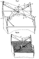
- Fig.2 the two are diagonally opposite one another Corners of a folded and rolled up on a shaft 3 Plane shown that consists of two different sized parts 1, 2 consists.
- the shaft 3 can be rotated via a drive 4, and on it are wound reels 5, 5 ', the preferred ones Design explained in more detail below with reference to FIG. 5 shall be.
- a protective tape 24 is applied to the longer tarpaulin part 1, on which winds the rope 6 'of the shorter tarpaulin part 2.
- the Cable 6 runs, starting from one winding roll 5, over a pulley 7 attached to a post 14 and one Tensioning roller 8 to an upper deflection roller 9 on an upright 11 '.
- the latter can consist of two independently rotatable rollers consist.
- the cable 6 runs from the deflection roller 9 a similar deflection roller 10 on the post 11 'and on a pull roller 12 on the tarpaulin part 1 and then back to the Deflection rollers 10, 9, the two going to the tension roller 12 Cable components move in the same direction.
- At one by the drive 4 e.g.
- the entire tarpaulin roof sits by means of the uprights 14, 14 'and 11, 11 ', which carry the tarpaulin or sunroof, on the walls of a cubic building 17.
- the Fig.2a leaves this in a more descriptive way Recognize wise.
- the flat roof of the building is in this Presentation dashed horizontally for better emphasis. On him the shadow of a person is drawn below the rolled up tarpaulin roof.
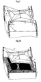
- FIG 3 shows the tarpaulin roof device shown in FIG with tensioned tarpaulin 1, 2, and also the drive shaft 3 is shown slightly bent upwards. This bend is desired and the consequence of the deflection rollers 7, 7 ' exerted inclined pull. If you extend the uprights (11, 11 ', 14, 14 'in Fig.2) upwards, so you can move the point of attack the direction of the diagonal pull of the roller suspension and thus change its effect. The stronger the diagonal pull, i.e. the higher the suspension of the deflection rollers 7, 7 ', the more of course the bend of the shaft 3 is stronger the possibility of moving the winding rollers 5, 5 'on the shaft 3.
- Figure 3 is also the use of UV protective strips 1 ", 2" shown on the edges of the tarpaulin parts, 1, 2, which protect the more sensitive tarpaulin when rolled up.
- FIG. 3a again shows the arrangement shown in FIG. however, for better illustration with one under the Shadow of tarpaulin standing people.
- the angular shadow of the Tarpaulin appears on the hatched flat roof.
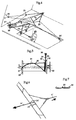
- FIG. Another exemplary embodiment is shown in FIG. in which the drivable shaft 3, on which the tarpaulin is rolled, is carried by a bracket spanning them or the like 18, which in turn by means of supports 19, 20 on a house wall or on Rafters can be attached.
- a bracket spanning them or the like 18, which in turn by means of supports 19, 20 on a house wall or on Rafters can be attached.
- a single winding roll 27 is used; two tension rollers 25, 25 'are resiliently suspended.
- the shaft 3 can also be cantilevered above it Building parts can be arranged. So the tarpaulin can e.g. one span a small courtyard and a flat roof. The possible use this embodiment is therefore very universal.
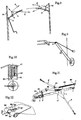
- FIG. 5 shows a preferred embodiment of the winding roll, whose roller body 31 is not completely cylindrical, but is slightly conical.
- the winding roll or drum is according to Fig.5 with their Axis of rotation e.g. on a wall 39 or on a stand attached.
- the material for the ropes 34, 35 is e.g. Steel wire and a polyamide for the drum. Every rope is made from a number (e.g. 19) of twisted wires. The rope strength depends on the desired resilience.
- the winding roll can in a conventional manner Electric motor to be housed to drive it.
- the Figure 7 represents schematically a cross section through the abrasion protection band 24 including one rope lying on it.
- Fig.8 which the generation of a shaft 3 bend Turn shows, again 4 designate a drive and 7 or 7 'each a pulley.
- the latter are here by means of a short Rope to a higher point of post 14 or 14 ' tense.
- the cable pulls 6, 6 ' are analogous to one another. from the respective winding roll 5 or 5 ', over which at an angle Deflection pulley 7 or 7 'braced above the upright 14 or 14' guided.
- the shaft 3 is bent slightly upwards.
- By moving the winding roll 5 or 5 'on the shaft 3 can the bending moment on shaft 3 can be changed.
- This effect can be done by moving the point of attachment of the suspension influence the deflection rollers 7, 7 'even further.
- FIG. 9 shows the suspension of a deflection roller 42 on a articulated and braced against a fixed point a tube formed support 40, at the upper end of one Bracket 41 is seated, which is inserted into the support tube.
- a Similar bracket is shown in Fig.10.
- Carrier tube inserted holder part 41 has a number of Bores 42 through which the tensioning cables can be guided, which are provided with crimped clamps 43 on the inside, so to prevent the respective rope from slipping.
- FIG. 11 shows an at least currently particularly preferred Tarpaulin roof arrangement, in which a cantilever 43 two guide rollers 44, 45 carries, by means of which the entire cable 6, 6 ' with pulley 46, 47 and above the sunroof the only spring 48 are kept high enough.
- the Angle between the cantilever 43 on the shaft 3 is approximately 30 °.
- Both the two pulleys 44, 45 and the Attachment of the single spring 48 are adjustable. It can two springs are also provided starting from point 49, one of which on the pulley 46 and the other on the Deflection roller 47 acts to the tension of the sun roof receive.
- On the edges of the tarpaulin are known per se Way protective strips attached to the tarpaulin itself in the Completely cover the rolled up condition.
- the shaft 3 with the Winding roll 5 can at one end, below the Krägägers 43, cardamic, whereas they are on the other Preferred end - in view of the bends in operation - is kept longitudinally displace
- a tab is shown in the diagonal, which for Connection of the tarpaulin with the associated pull rope 6 or 6 'serves.
- This is in a double loop 62, the a solid fabric is made, a slotted bolt 63.
- the loop 62 is attached to the top of the tarpaulin.
- the Traction rope 6 or 6 ' is when inserting the bolt 63 in it Slot 64 inserted after it was previously crimped with Terminals 66, 66 'was provided, these terminals 66, 66' one Hold rope loop 67 together.
- the operation of the system i.e. stretching or curling the sunroof or tarpaulin in general, can also be program controlled take place, so that e.g. at certain times and / or the tarpaulin automatically in certain weather conditions is rolled out or rolled up. This can be done in known Sensors are used in a circuit known per se.
Landscapes
- Engineering & Computer Science (AREA)
- Architecture (AREA)
- Civil Engineering (AREA)
- Structural Engineering (AREA)
- Electromagnetism (AREA)
- Physics & Mathematics (AREA)
- Tents Or Canopies (AREA)
- Steroid Compounds (AREA)
- Building Awnings And Sunshades (AREA)
- Massaging Devices (AREA)
- Mechanical Treatment Of Semiconductor (AREA)
- Inorganic Insulating Materials (AREA)
- Soil Working Implements (AREA)
- Compression-Type Refrigeration Machines With Reversible Cycles (AREA)
- Glass Compositions (AREA)
- Addition Polymer Or Copolymer, Post-Treatments, Or Chemical Modifications (AREA)
Abstract
Description
Die Erfindung betrifft allgemein ein der Größe nach verstellbares Planendach, z.B. Sonnendach, und mehr im einzelnen ein verstellbares Planendach mit einer Plane, die im Bereich einer Teil- oder Faltlinie an einer einzelnen, an Trägern drehbar gelagerten und mit einem einzigen Antrieb versehenen Welle befestigt und auf dieser aufrollbar ist.The invention relates generally to an adjustable size Tarpaulin roof, e.g. Sun canopy, and more in detail an adjustable tarpaulin roof with a tarpaulin in the area a part or fold line on a single, rotatable on straps mounted shaft and provided with a single drive attached and can be rolled up on this.
Bei bekannten Planendach-Anordnungen ist eine Plane auf einer drehbaren, von Hand oder motorisch drehbaren Welle angebracht, wobei der eine Rand der Plane an der Welle befestigt ist. Von dieser Welle aus kann die Plane in eine Richtung, unter Verwendung eines Kragträgers, ausgezogen werden. Diese bekannten Anordnungen eignen sich jedoch nur schlecht für die Überdachung größerer Flächen, weil sie zu stark durchhängen, und weil infolge der Auskragung sehr hohe Kräfte auf den auskragenden Träger und seine Befestigungselemente wirken.In known tarpaulin roof arrangements, a tarpaulin is open a rotatable shaft that can be rotated by hand or motor, one edge of the tarpaulin attached to the shaft is. From this wave the tarpaulin can move in one direction, under Using a cantilever. These well-known Arrangements are, however, poorly suited for roofing larger areas because they sag too much and as a result the cantilever very high forces on the cantilever and its fasteners work.
Ein Planendach der eingangs angeführten Art ist aus der US 4 724 882 A bekannt. Dieses bekannte Planendach ist mit einer Hauptwelle ausgerüstet, von der bzw. auf die zwei rechteckige Planenteile ab-/aufgewickelt werden. Über das - nur in geringem Maß mögliche - Aufrollen dieser Planenteile auf der Welle wird eine Schrägstellung der Dachflächen gesteuert, welche ferner über schräge Teleskopstützen abgestützt werden.A tarpaulin roof of the type mentioned is from the US 4,724,882 A is known. This well-known tarpaulin roof comes with a Main shaft equipped, from or to the two rectangular Tarpaulin parts are unwound / wound up. About that - only a little Measure possible - rolling up these tarpaulin parts on the shaft controlled an inclination of the roof surfaces, which further be supported on inclined telescopic supports.
Aus der FR 2 431 827 A ist ein andersartiges Planendach
bekannt, bei dem auf einer mit einem Antrieb versehenen Antriebswelle
nur die Seile von Seilzügen auf- bzw. abgewickelt
werden. Zwei zugehörige, voneinander getrennte Planen werden
hingegen je auf einem Stab aufgerollt, wenn das Planendach
geöffnet werden soll. Die einen Seilzüge greifen beim Schließen
des Daches an Zugstangen an, die an den oberen Längsrändern der
Planen angebracht sind. Die Seile der anderen Seilzüge werden
beim Öffnen des Daches auf der Welle aufgerollt und dienen als
Antriebsmittel zum Abrollen der Aufroll-Stäbe auf bogenförmigen
Gestellteilen, wobei die jeweilige Plane auf dem Stab aufgerollt
wird.
Es ist ein Ziel der Erfindung, ein Planendach wie eingangs angegeben zu schaffen, mit dem große Flächen überdacht werden können, wobei durch entsprechende Krafteinleitung die Plane gut gespannt gehalten werden kann, ohne daß Tragstrukturen über Gebühr beansprucht werden.It is an object of the invention to have a tarpaulin roof as in the beginning to create, with which large areas are covered can, the tarpaulin well by appropriate force introduction can be kept taut without supporting structures over Fee will be claimed.
Weiters ist es ein Ziel der Erfindung, eine für das erfindungsgemäße Planendach besonders geeignete Seilzug-Wickelrolle vorzusehen, die ein enges Aufrollen der unter Zug stehenden Seile erlaubt.Furthermore, it is an object of the invention, one for the invention Tarpaulin roof especially suitable cable pull winding roller to provide a tight rolling up of the train Ropes allowed.
Die Erfindung geht von der Überlegung aus, daß es vorteilhaft wäre, die Plane in ihrer Mitte und an ihren Enden aufzuhängen bzw. abzustützen, wobei sie gleichzeitig immer möglichst gespannt sein soll. Eine derartige Anordnung kann dann größere Flächen überdecken, wobei die Aufhängungspunkte der ausziehbaren bzw. ausgezogenen Ecken der Plane nur die Spannung der Plane und einen kleinen Teil des Gewichtes der ausgezogenen Plane aufzunehmen haben.The invention is based on the consideration that it is advantageous would be to hang the tarpaulin in the middle and at its ends or to support, while at the same time whenever possible to be excited. Such an arrangement can then be larger Cover surfaces, the suspension points of the extendable or extended corners of the tarpaulin only the tension of the tarpaulin and take up a small part of the weight of the extended tarpaulin to have.
Das erfindungsgemäße Planendach der eingangs angeführten Art ist dadurch gekennzeichnet, daß zum Auf- bzw. Abrollen der durch die Teil- oder Faltlinie gegebenen Planenteile wenigstens zwei Seilzüge vorgesehen sind, die an den Planenteilen angreifen und auf die Welle aufrollbar sind. Vorzugsweise sind dabei die Seilzüge, die je an einem Planenteil angreifen, auf wenigstens eine auf der Welle sitzende Wickelrolle aufrollbar.The tarpaulin according to the invention of the type mentioned is characterized in that for rolling up and down the part or fold line given tarpaulin parts at least two Cable pulls are provided which attack the tarpaulin parts and can be rolled up onto the shaft. The cables are preferably who attack one part of the tarpaulin, at least one roll on the shaft can be rolled up.
Somit ist beim vorliegenden Planendach, insbesondere Sonnendach, die Plane (ein Segeltuch oder dergl.) entweder an einer Linie, z.B. einer diagonalen Symmetrielinie, gefaltet, wodurch zwei Planenteile gebildet werden, oder sie besteht aus zwei getrennten Teilen, deren Randberührungslinien quasi eine "Falt"linie bilden bzw. der Faltlinie entsprechen; die Planenteile können dabei verschieden groß und/oder verschieden geformt sein. Im Bereich der Faltlinie (oder Trennlinie) ist die Plane bzw. sind die Planenteile an der antreibbaren Welle befestigt; zum Auf- bzw. Abrollen der Planenteile sind bevorzugt zwei Seilzüge vorgesehen, die je an einem Planenteil angreifen und auf die Welle bzw. auf ihr sitzende Wickelrollen aufrollbar sind. Zweckmäßigerweise wird die Plane mit Segellatten-artigen Flachprofilen, z.B. aus GFK-Material, parallel zur Aufrollwelle versehen.Thus, in the present tarpaulin roof, especially the sun roof, the tarpaulin (a canvas or the like) either on one Line, e.g. a diagonal line of symmetry, folded, whereby two tarpaulin parts are formed, or it consists of two separate Parts whose edge contact lines are like a "fold" line form or correspond to the fold line; the tarpaulin parts can be of different sizes and / or different shapes. In the area of the fold line (or dividing line) the tarpaulin or the tarpaulin parts are attached to the drivable shaft; to the Rolling up or rolling off the tarpaulin parts is preferably two cable pulls provided that each attack on a tarpaulin part and on the Shaft or winding rollers sitting on it can be rolled up. Conveniently the tarpaulin is made with flat battens e.g. made of GRP material, provided parallel to the reel shaft.
An sich ist das Aufrollen eines gefaltenen Tuches z.B. bei Vorsegeln von Booten bekannt, wo das Tuch auf das Vorstag aufgewickelt ist und beim Abrollen mittels zweier getrennter Zugvorrichtungen zu einem sogenannten Schmetterlingssegel ausgezogen werden kann, wodurch es sich besonders für das Segeln im Passat eignet. Dieser Anwendungsbereich liegt jedoch weit entfernt vom Anwendungsbereich der Erfindung, die Planendächer, vorzugsweise Sonnendächer, betrifft. Außerdem wird bei der Erfindung beim Abrollen und Aufrollen nur ein einziger Antrieb in Zuordnung zu einer Welle verwendet.In itself, rolling up a folded cloth is e.g. at Foresailing boats are known where the cloth is wound onto the forestay and when unrolling by means of two separate pulling devices pulled out to a so-called butterfly sail can be, which makes it particularly suitable for sailing in the Passat is suitable. However, this area of application is far from Scope of the invention, the tarpaulin roofs, preferably Canopies. In addition, the invention Unrolling and rolling up only one drive in assignment used a wave.
Durch die "doppelte", gegebenenfalls zweilagige (bei entsprechender Überlappung der Planenteile) Aufwicklung der Plane, beginnend im Bereich der Falt- oder Teilungslinie, sind auch die verschiedensten Gestaltungsmöglichkeiten für die Form des Planendachs gegeben. Hierbei ist es für eine gute Kräftekompensation vorteilhaft, wenn die Punkte der Planenteile, an denen der jeweilige Seilzug befestigt ist, auf ein und derselben zur Welle senkrechten Linie liegen, sowie auch, wenn die Planenteile zueinander symmetrisch sind. Andererseits ist es für bestimmte Formgebungen günstig, wenn die Punkte der Planenteile, an denen der jeweilige Seilzug befestigt ist, auf zwei verschiedenen, zueinander parallelen und zur Welle senkrechten Linie liegen, bzw. wenn die Planenteile im ausgerollten Zustand an der Faltlinie gegeneinander versetzt sind. Für das Ab- und Aufrollen ist es auch von Vorteil, wenn die Planenteile dreieckig sind.Through the "double", possibly two-ply (with the corresponding Overlap of the tarpaulin parts) starting in the area of the fold or dividing line are also various design options for the shape of the Given the tarpaulin. Here it is for good force compensation advantageous if the points of the tarpaulin parts where the respective cable is attached to one and the same Wave vertical line lie, as well as when the tarpaulin parts are symmetrical to each other. On the other hand, it is for certain Shapes favorable if the points of the tarpaulin parts where the respective cable is attached to two different, line parallel to each other and perpendicular to the shaft, or when the tarpaulin parts are rolled out on the fold line are offset from each other. For unrolling and rolling up it is also an advantage if the tarpaulin parts are triangular.
Zum Ausgleich der verschiedenen Abrollängen und zur Spannung der Seilzüge kann zumindest ein elastisches Glied, insbesondere eine Schraubenfeder, vorgesehen werden. Dabei ist es besonders vorteilhaft, wenn das elastische Glied so angeordnet ist, daß es die zwei (oder mehr) Seilzüge zueinander zieht, wobei im Falle eines einzigen elastischen Gliedes an diesem zwei Umlenkrollen oder eine Zweifachrolle befestigt sind bzw. ist, über welche je ein Seilzug geführt ist. Weiters ist es hier günstig, wenn der Befestigungspunkt des elastischen Gliedes in der Höhe über der Welle verstellbar ist und die Zuführung der beiden Seilzüge zu einer einzigen Wickelrolle über Führungsrollen erfolgt, die an einem Kragträger befestigt sind, so daß die zur Wickelrolle führenden Seilzüge ausreichend hoch über dem Dach gehalten sind. Andererseits ist es für ein gleichmäßiges Spannen der Seilzüge von Vorteil, wenn zwei elastische Glieder so angeordnet sind, daß sie die zwei Seilzüge zueinander ziehen, wobei jedes elastische Glied an jedem Ende über eine daran befestigte Spannrolle mit einem der Seilzüge verbunden ist.To compensate for the different unwinding lengths and for tension the cable pulls can have at least one elastic link, in particular a coil spring. It is special advantageous if the elastic member is arranged so that it which pulls two (or more) cables towards each other, being in the case of a single elastic link on these two pulleys or a double roll are attached, over which each a cable is guided. It is also favorable here if the Attachment point of the elastic member at a height above the Shaft is adjustable and the feed of the two cables is too a single winding roll is made via guide rolls that are attached to a cantilever are attached so that the winding roll leading cables are kept high enough above the roof. On the other hand, it is for even tensioning of the cables advantageous if two elastic links are arranged so that they pull the two cables towards each other, each elastic link at each end via an attached one Tension pulley is connected to one of the cables.
Eine für die Überdachung besonders großer Flächen gut geeignete Ausführungsform ist dadurch gekennzeichnet, daß auf der Antriebswelle seitlich der aufgerollten Plane je eine Wickelrolle befestigt ist, wobei von jeder der beiden Wickelrollen zwei an ihr befestigte Seile ausgehen, deren jedes dem einen oder anderen Seilzug zugehört und über Umlenkrollen, die an Festpunkten, z.B. Stehern, aufgehängt sind, zu Spannrollen, die die beiden Seilzüge federnd zueinander ziehen, über an weiteren Festpunkten aufgehängten Umlenkrollen zu je einer an jedem Planenteil befestigten Zugrolle geführt ist und von dort über Umlenkrollen und Spannrollen zur anderen Wickelrolle verläuft; dabei kann der Verlauf der beiden Seilzüge gleichartig und symmetrisch sein.A well-suited for roofing particularly large areas Embodiment is characterized in that on the Drive shaft on the side of the rolled tarpaulin, one winding roll each is attached, with each of the two winding rollers run out of two ropes attached to it, each one to the one or other cable pull listened to and via pulleys attached to Fixed points, e.g. Stand, are hung, to idlers that pull the two cables in a springy manner towards each other Fixed pulleys attached to each pulley Tarpaulin part attached pull roller is guided and from there over Deflection rollers and tensioning rollers run to the other winding roller; the course of the two cables can be the same and be symmetrical.
Für eine stabile Anbringung ist es von Vorteil, wenn die Welle an jedem ihrer beiden Enden fest, z.B. an einem Steher, gelagert ist, wobei die eine Lagerung als motorischer Antrieb oder Handantrieb ausgebildet ist. Für besonders flexible Anwendungen, insbesondere bei kleineren Planendächern, ist es andererseits auch günstig, wenn die Welle an einem sie überspannenden Bügel gelagert ist, welcher seinerseits durch fest angebrachte Träger gehalten ist. Dabei hat es sich weiters als vorteilhaft erwiesen, wenn auf der Welle nur eine einzige Wickelrolle sitzt, wobei jeder von dieser Wickelrolle ausgehende Seilzug über eine Umlenkrolle zu Spannrollen und weiter zu an Fixpunkten sitzenden Umlenkrollen und von dort zu den Zugecken der Planenteile verläuft.For a stable attachment, it is advantageous if the Shaft fixed at each of its two ends, e.g. on a stand, is mounted, the one bearing as a motor drive or manual drive is formed. For particularly flexible applications, on the other hand, especially with smaller tarpaulin roofs also cheap if the shaft spans one of them Stirrup is stored, which in turn by firmly attached Carrier is held. It has also proven advantageous proven if there is only one winding roller on the shaft, whereby each cable pull starting from this winding roll has a Deflection pulley to tension pulleys and further to those located at fixed points Deflection rollers and from there to the corner of the tarpaulin parts runs.
Es ist ferner denkbar, daß die ausgezogenen Planenteile nicht gemäß einer gemeinsamen Ebene verlaufen, sondern daß sie in einem von 180° abweichenden Winkel zueinander bzw. ausziehbar sind, etwa zu einer Art Zeltdach ausgezogen werden können.It is also conceivable that the extended tarpaulin parts not run according to a common level, but that they extendable at an angle other than 180 ° are, for example, can be extended to a kind of tent roof.
Ferner ist es günstig, wenn jeder der beiden Seilzüge ausgehend von den Wickelrollen zuerst über eine, über oder unter der Wellenlagerung fest aufgehängte Rolle geführt ist, wobei der Zug im Seil so bemessen ist, daß eine gewünschte Biegung der Welle, vorzugsweise nach oben, erzielt wird. Mit einer derartigen Biegung der Welle kann einem Durchhängen der Planenteile entgegengewirkt werden.It is also advantageous if each of the two cables starting from the winding rolls first over, over or under the shaft bearing is firmly suspended role, the Train in the rope is dimensioned so that a desired bend the Wave, preferably upwards, is achieved. With such a Bending the shaft can cause sagging of the tarpaulin parts be counteracted.
Sodann ist es vorteilhaft, wenn die Umlenk- und allenfalls die Spannrollen feststehende, seitlich der eigentlichen Rolle angebrachte, im Durchmesser wesentlich größere Seitenplatten aufweisen, die ein Herausspringen des Seiles verhindern.Then it is advantageous if the deflection and at most the tensioning rollers are fixed, to the side of the actual roller attached side plates, much larger in diameter have, which prevent the rope from jumping out.
Weiters ist es von Vorteil, wenn vier die Plane und die Seilzüge tragende Steher vorgesehen sind, wobei zwei diagonal gegenüber liegende Steher die Antriebswelle tragen und die beiden anderen Seilrollen zur Umlenkung. Dabei können die Steher als abgespannte Masten, insbesondere Rohre, ausgebildet sein.It is also an advantage if four the tarpaulin and the Rope-supporting posts are provided, two diagonally opposite pillars carry the drive shaft and the two other pulleys for deflection. The upright can be designed as guyed masts, especially pipes.
Aus Gründen der Flexibilität ist es ferner zweckmäßig, wenn die Wickelrollen örtlich verstellbar sind.For reasons of flexibility, it is also appropriate if the winding rolls are locally adjustable.
Auch hat es sich als vorteilhaft erwiesen, wenn an jedem der beiden Seilzüge bzw. ihren Befestigungsstellen mindestens eine Sollbruchstelle als Schutz gegen Überlastung, z.B. durch Winddruck, vorgesehen ist.It has also proven to be advantageous if each of the two cables or their attachment points at least one Predetermined breaking point as protection against overload, e.g. by Wind pressure, is provided.
Zur Justierung des Planendachs ist es von Vorteil, wenn die Welle an zumindest einem Ende verschiebbar und/oder kardanisch gelagert ist.To adjust the tarpaulin roof, it is advantageous if the Shaft displaceable and / or gimbal at at least one end is stored.
Weiters ist es günstig, wenn im Falle von ungleich langen Planenteilen auf dem längeren Planenteil ein Scheuerschutzband, gegebenenfalls mit Seitenwülsten, angebracht ist, auf welches sich das Zugseil des kürzeren Planenteils aufwickelt. Überdies kann jeder Teil der Plane mit Randschutzstreifen versehen sein, die so bemessen sind, daß sie die Plane im aufgerollten Zustand abdecken, wodurch ein Schutz der Plane im aufgerollten Zustand automatisch erhalten wird.Furthermore, it is favorable if in the case of unequal lengths Tarpaulin parts on the longer part of the tarpaulin, optionally with side beads, is attached to which the pull rope of the shorter tarpaulin part winds up. Moreover each part of the tarpaulin can be provided with edge protection strips, which are dimensioned so that they cover the tarpaulin when rolled up cover, thereby protecting the tarpaulin when rolled up is automatically received.
Um ein geordnetes, enges Aufwickeln der Seilzüge trotz der in ihnen gegebenen Spannung sicherzustellen, ist eine vorteilhafte Ausführungsform vorgesehen, die dadurch gekennzeichnet, daß die bzw. jede Wickelrolle bezüglich ihrer Drehachse leicht konisch ist, wobei der Konuswinkel gegenüber der Achse vorzugsweise unter 1° liegt, und daß die Wickelrolle an ihrem dickeren Ende gerundet in eine im Durchmesser größere Endplatte übergeht und die Zuführung des bzw. der aufzuwickelnden Seile knapp entlang der Endplatte im Bereich des größten Durchmessers der Rundung erfolgt, wobei das aufzuwickelnde Seil bzw. die Seile im Bereiche des dünneren Endes der Wickelrolle, vorzugsweise an einer dort befindlichen Endplatte, befestigbar bzw. befestigt sind.To ensure an orderly, tight winding of the cables despite the Ensuring tension in them is an advantageous one Embodiment provided which are characterized in that the or each winding roll slightly with respect to its axis of rotation is conical, the cone angle being preferred to the axis is below 1 °, and that the winding roll on its thicker Rounded end into a larger end plate in diameter and the supply of the rope (s) to be wound up is scarce along the end plate in the area of the largest diameter of the Rounding takes place, with the rope to be wound or the ropes in Areas of the thinner end of the winding roll, preferably on an end plate located there, attachable or attached are.
Es sei hier erwähnt, daß es an sich zur Zwischenspeicherung von Fäden bei Textilgarnwicklern bekannt ist, Wickeltrommeln mit sich verkleinerndem Durchmesser vorzusehen, vgl. beispielsweise DE 31 23 760 A, DD 221 984 A und CH 624 362 A; diese für Textileinrichtungen gedachte Art der Aufwicklung arbeitet jedoch mit Fäden, die laufend zu- und abgeführt werden, und die nicht mit einem Ende an der Wickeltrommel befestigt sind.It should be mentioned here that it is for temporary storage of threads in textile yarn winders is known, with winding drums to provide a decreasing diameter, cf. for example DE 31 23 760 A, DD 221 984 A and CH 624 362 A; this for However, the type of reeling intended for textile devices works with threads that are constantly being fed in and out and that are not are attached at one end to the winding drum.
Um die Seilführung auch im Fall von zwei oder mehr Seilen einfach zu halten, ist es zweckmäßig, wenn diese Seile über Mehrfachrollen oder Rollen mit mehreren Rillen geführt sind.The rope guide also in the case of two or more ropes easy to hold, it is convenient if these ropes over Multiple rolls or rolls with multiple grooves are guided.
Zur platzsparenden Anbringung eines Antriebs ist es weiters günstig, wenn die bzw. eine Wickelrolle innen einen Elektromotor aufweist, der ihren Außenmantel antreibt.It is also for space-saving attachment of a drive favorable if the or a winding roll inside an electric motor has that drives their outer jacket.
Auch ist es von Vorteil, wenn die Gleitfähigkeit des oder der aufzuwickelnden Seile mit der Gleitfähigkeit des Rollenmantels und dem Radius der Rundung des Überganges von der Manteloberfläche zur Endplatte so abgestimmt ist, daß die Seilwindungen am annähernd größten Rundungsdurchmesser eine ausreichend große in Richtung der Rollenachse gerichtete Druckkraft auf die bereits vorher aufgewickelten Seilwindungen erzeugen, wodurch diese Seilwindungen kontinuierlich auf den Rollenmantel gegen das schlankere Ende zu geschoben werden. It is also advantageous if the lubricity of the or of the ropes to be wound up with the sliding ability of the roll cover and the radius of the rounding of the transition from the surface of the jacket is matched to the end plate so that the cable turns sufficient at the approximately largest rounding diameter large pressure force directed in the direction of the roller axis on the generate previously wound rope turns, whereby these turns of rope continuously against the roller sheath the slimmer end to be pushed.
Es hat sich überdies als günstig erwiesen, wenn Abspannseile an Stehern oder dergl., die rohrförmig ausgebildet sind, mittels in das Rohrende eingesteckter Pfropfen befestigt sind, welche Pfropfen das Rohrende übergreifen und eine Anzahl Bohrungen, die z.B. kreisförmig angeordnet sind, aufweisen, wobei die Abspannseile durch diese Bohrungen geführt und unterhalb derselben mit aufgepreßten Muffen versehen sind, die ein Herausrutschen verhindern.It has also proven to be beneficial if guy ropes on stands or the like, which are tubular, by means of plugs inserted into the pipe end are attached, which Graft overlap the pipe end and a number of holes that e.g. are arranged in a circle, with the guy ropes passed through these holes and below them pressed-on sleeves are provided that slip out prevent.
Weiters ist es vorteilhaft, wenn zur Befestigung der Seile an den Planenteilen an diesen befestigte Zweifachlaschen dienen, durch welche ein geschlitzter Bolzen geschoben ist, durch dessen Schlitz das Seil gesteckt ist, das dahinter mit aufgepreßten Muffen versehen ist, die eine Seilschlaufe zusammenhalten.Furthermore, it is advantageous if for fastening the ropes double flaps attached to the tarpaulin parts, through which a slotted bolt is pushed, through which Slot the rope is inserted, the one behind it is pressed on Is provided sleeves that hold a rope loop together.
Von Vorteil ist es schließlich, wenn die Welle, auf der die Plane bzw. die Planenteile aufrollbar sind, aus einem mit einer Nut versehenen Rohr, vorzugsweise einem Stahlrohr, besteht, wobei die Plane mittels eines in die Nut eingeschobenen Keders am Rohr befestigt ist.Finally, it is advantageous if the shaft on which the Tarpaulin or the tarpaulin parts can be rolled up, from one with one Grooved tube, preferably a steel tube, the tarpaulin using a welt inserted into the groove is attached to the pipe.
Die Erfindung wird anhand von in der Zeichnung dargestellten,
bevorzugten Ausführungsbeispielen, auf die sie jedoch
nicht beschränkt sein soll, noch weiter erläutert. Es zeigen:
In Fig.1a ist eine Sonnendach-Plane mit zwei Planenteilen 1,
2 gezeigt, die verschieden in Form und Größe sind, jedoch liegen
ihre beiden Spitzen S, an denen Zugseile 6 bzw. 6' angreifen,
auf ein und derselben senkrecht zur Achse einer Welle 3 verlaufenden
strichpunktierten Linie. Nach Fig.1b können die durch die
Spitzen S der Planenteile 1, 2 gehenden Zugrichtungen (Seile 6,
6') auch parallel nebeneinander verlaufen, wobei die Planenteile
1, 2 verschiedene Form und Größe haben können und auf der
Wellenachse gegeneinander verschoben sind. Eine vollkommen
symmetrische Anordnung der Planenteile 1, 2 ist in der Fig.1c
dargestellt. Hingegen zeigt die Fig.1d eine Anordnung der Planen
bzw. Planenteile 1, 2, bei welcher beide im ausgerollten Zustand
zur Gänze gegeneinander versetzt sind. Alle diese grundsätzlichen
Planen-Anordnungen können im Rahmen der Erfindung Verwendung
finden. Die Planenteile 1, 2 können dabei in an sich herkömmlicher
und daher nicht weiter veranschaulichter Weise auf
der Welle 3 entlang ihrer Faltlinie bzw. entlang ihrer Ränder
(wenn gesonderte Planenteile vorliegen) befestigt sein. Vorzugsweise
besteht die Welle 3 aus einem genuteten Rohr, wobei die
Nut dazu dient, die Planenteile mittels eines daran befindlichen
Keders zu befestigen, indem dieser in die Nut eingeschoben wird.1a shows a sunroof tarpaulin with two
In Fig.2 sind die beiden einander diagonal gegenüberliegenden
Ecken einer gefalteten und auf einer Welle 3 aufgerollten
Plane gezeigt, die aus zwei verschieden großen Teilen 1, 2
besteht. Die Welle 3 kann über einen Antrieb 4 gedreht werden,
und auf ihr sind Wickelrollen 5, 5' befestigt, deren bevorzugte
Ausgestaltung nachstehend anhand der Fig.5 noch näher erläutert
werden soll. Von jeder Wickelrolle 5, 5' gehen zwei Seilzüge 6,
6' aus. Da die beiden Planenteile 1, 2 bei diesem Ausführungsbeispiel
in Zugrichtung ungleich lang sind (s. auch Fig.3), ist
auf dem längeren Planenteil 1 ein Schutzband 24 aufgebracht, auf
dem sich das Seil 6' des kürzeren Planenteils 2 aufwickelt. Der
Seilzug 6 verläuft, ausgehend von der einen Wickelrolle 5, über
eine an einem Steher 14 angehängte Umlenkrolle 7 und eine
Spannrolle 8 zu einer oberen Umlenkrolle 9 an einem Steher 11'.
Letztere kann aus zwei unabhängig voneinander drehbaren Rollen
bestehen. Sodann verläuft der Seilzug 6 von der Umlenkrolle 9 zu
einer gleichartigen Umlenkrolle 10 am Steher 11' und weiter über
eine Zugrolle 12 am Planenteil 1 sowie dann zurück zu den
Umlenkrollen 10, 9, wobei die beiden zur Zugrolle 12 gehenden
Seilzugteile sich in der gleichen Richtung bewegen. Sodann führt
der Seilzug 6 über eine Spannrolle 13 und eine an einem Steher
14' angehängte Umlenkrolle 7' zur anderen Wickelrolle 5', an der
er befestigt ist.In Fig.2 the two are diagonally opposite one another
Corners of a folded and rolled up on a
Der andere Seilzug 6' führt in analoger Weise von der einen
Wickelrolle 5, an der er befestigt ist, über die Umlenkrolle 7
und eine Spannrolle 13', sodann über an einem Steher 11
befestigte Umlenkrollen 9', 10' zu einer Zugrolle 12' an der
Ecke des kleineren (kürzeren) Planenteils und um diese Zugrolle
12' herum zurück zu den Umlenkrollen 10', 9' von da weiter zu
einer Spannrolle 8' sowie zur Umlenkrolle 7' am Steher 14' und
schließlich zur anderen Wickelrolle 5'. Die beiden Enden beider
Seilzüge 6, 6' sind an den Wickelrollen 5, 5' befestigt. Bei
einer durch den Antrieb 4 (z.B. schematisch mit einer Kurbel
gezeigt) bewirkten Drehung der Welle 3 in dem durch die bei den
beiden Wickelrollen 5, 5' eingezeichneten Pfeile angedeuteten
Uhrzeigersinn (in Fig.2 von links gesehen) werden die Planenteile
1, 2 von der Welle 3 durch die Seilzüge 6, 6' abgezogen.
Elastische Glieder 15, 16, z.B. Federn, insbesondere Schrauben-
oder Wendelfedern, halten die Seilzüge 6, 6' gespannt. (Wie in
Fig.11 gezeigt kann an sich auch bloß eine Feder 48 angeordnet
werden).The other cable 6 'leads in an analogous manner from one
Das ganze Planendach sitzt mittels der Steher 14, 14' und
11, 11', die das Planen- oder Sonnendach tragen, an den Wänden
eines kubischen Gebäudes 17. Die Fig.2a läßt dies in anschaulicher
Weise erkennen. Das ebene Dach des Gebäudes ist in dieser
Darstellung zwecks besserer Hervorhebung horizontal gestrichelt.
Auf ihm zeichnet sich der Schatten eines Menschen unterhalb des
eingerollten Planendachs ab.The entire tarpaulin roof sits by means of the
Die Fig.3 zeigt die in Fig.2 dargestellte Planendach-Vorrichtung
mit ausgespannter Plane 1, 2, wobei außerdem die Antriebswelle
3 leicht nach oben gebogen gezeigt ist. Diese Biegung
ist erwünscht und die Folge des auf die Umlenkrollen 7, 7'
ausgeübten Schrägzuges. Verlängert man die Steher (11, 11', 14,
14' in Fig.2) nach oben, so kann man durch Verschieben des Angriffspunktes
der Rollenaufhängung die Richtung des Schrägzuges
und damit seine Wirkung verändern. Je stärker der Schrägzug ist,
d.h. je höher die Aufhängung der Umlenkrollen 7, 7' ist, desto
stärker ist natürlich die Biegung der Welle 3. Außerdem besteht
die Möglichkeit, die Wickelrollen 5, 5' auf der Welle 3 zu verschieben.
In Fig.3 ist weiters die Verwendung von UV-Schutzstreifen
1", 2" an den Rändern der Planenteile, 1, 2 gezeigt,
die im aufgerollten Zustand die empfindlichere Plane schützen.3 shows the tarpaulin roof device shown in FIG
with
Die Fig.3a zeigt wieder die in Fig.3 dargestellte Anordnung, jedoch zur besseren Veranschaulichung mit einem unter dem Schatten der Plane stehenden Menschen. Der eckig Schatten der Plane zeichnet sich auf dem schraffierten Flachdach ab.3a again shows the arrangement shown in FIG. however, for better illustration with one under the Shadow of tarpaulin standing people. The angular shadow of the Tarpaulin appears on the hatched flat roof.
In Fig.4 ist ein anderes Ausführungsbeispiel dargestellt,
bei dem die antreibbare Welle 3, auf die die Plane gerollt wird,
von einem sie überspannenden Bügel oder dergl. 18 getragen wird,
der seinerseits mittels Trägern 19, 20 an einer Hauswand oder an
Dachsparren befestigt werden kann. Bei dieser einfacheren Ausführungsform
wird auch nur eine einzige Wickelrolle 27 verwendet;
zwei Spannrollen 25, 25' sind federnd aufgehängt. Auf diese
Weise kann die Welle 3 auch auskragend über darunter liegende
Gebäudeteile angeordnet sein. So kann die Plane z.B. einen
kleinen Hof und ein Flachdach überspannen. Die Verwendungsmöglichkeit
dieser Ausführungsform ist also sehr universell.Another exemplary embodiment is shown in FIG.
in which the
Die Fig.5 zeigt eine bevorzugte Ausführungsform der Wickelrolle,
deren Rollenkörper 31 nicht vollkommen zylindrisch, sondern
leicht kegelförmig ist. Je nach Material von Rolle und Seil
liegt der Winkel zwischen einer Erzeugenden 30 des Kegelmantels
und der Achse der Welle 3 zwischen fast 0° und 2°. Bevorzugt
wird ein Winkel von 0,5°. Dadurch wird ein selbsttätiges
Nachrücken der vom (in Fig.5 rechten) Anfangsbereich größeren
Durchmessers kommenden, d.h. dort aufgewickelten Windungen
entlang des Rollenkörpers 31 erreicht. Es ist daher im Gegensatz
zu bekannten Wickelrollen nicht nötig, die Rolle selbst oder den
Seilzuführungspunkt zu verschieben, um zu erreichen, daß sich
die Windungen einwandfrei nebeneinander legen. Die Rolle gemäß
Fig.5 besitzt weiters an dem einen Ende eine im Durchmesser
größere Endplatte 32, in die sie gerundet übergeht. Diese
Rundung ist mit 33 bezeichnet. Mit 34 bzw. 35 sind zwei Seile
bezeichnet, die über eine Rolle 36 geführt werden. Auf der
Trommeloberfläche, d.h. dem Rollenmantel, liegen die Windungen
eng nebeneinander. Bei 37 sind die Seile 34, 35 an einer
gegenüberliegenden Endplatte 38 befestigt. Bei Drehung der Rolle
laufen die beiden Seile 34, 35 am dickeren, bei 33 gerundeten
Ende neben der Endplatte 32 auf und rutschen nebeneinander auf
dem Rollenkörper 31 in Richtung zum geringeren Durchmesser. So
schieben sich die Windungen langsam gegen die andere Endplatte
38 hin. Die Wickelrolle oder -trommel ist gemäß Fig.5 mit ihrer
Drehachse dabei z.B. an einer Wand 39 oder an einem Steher
befestigt. Als Werkstoff für die Seile 34, 35 eignet sich z.B.
Stahldraht und für die Trommel ein Polyamid. Jedes Seil besteht
aus einer Anzahl (z.B. 19) verdrillter Drähte. Die Seilstärke
richtet sich nach der gewünschten Belastbarkeit.5 shows a preferred embodiment of the winding roll,
whose
In der Wickelrolle kann in an sich bekannter Weise ein Elektromotor zu ihrem Antrieb untergebracht sein.In the winding roll can in a conventional manner Electric motor to be housed to drive it.
In den Fig.6 und 7 ist das bereits vorstehend erwähnte
Scheuerschutzband 24 mehr im Detail und mit verdickten Rändern
24' gezeigt, zwischen die sich das zusammen mit dem jeweiligen
Planenteil aufgewickelte Seil legt. Die Fig.7 stellt schematisch
einen Querschnitt durch das Scheuerschutzband 24 samt einem
darauf liegenden Seil dar.6 and 7 that is already mentioned above
In Fig.8, welche die Erzeugung eines die Welle 3 biegenden
Zuges zeigt, bezeichnen wieder 4 einen Antrieb und 7 bzw. 7' je
eine Umlenkrolle. Letztere sind hier jedoch mittels eines kurzen
Seiles zu einem höherliegenden Punkt des Stehers 14 bzw. 14'
verspannt. In zueinander analoger Weise sind die Seilzüge 6, 6'
von der jeweiligen Wickelrolle 5 bzw. 5', über die nach schräg
oben zum Steher 14 bzw. 14' verspannte Umlenkrolle 7 bzw. 7'
geführt. Hierdurch wird die Welle 3 etwas nach oben gebogen.
Durch Verschieben der Wickelrolle 5 bzw. 5' auf der Welle 3 kann
das Biegemoment auf die Welle 3 verändert werden. Außerdem
erlaubt die örtliche Verstellung der Wickelrollen 5, 5' einen
Ausgleich der Vorspannung an den Seilzügen 6, 6'. Diesen Effekt
kann man durch Verschieben des Angriffspunktes der Aufhängung
der Umlenkrollen 7, 7' noch weiter beeinflussen.In Fig.8, which the generation of a
Die Fig.9 zeigt die Aufhängung einer Umlenkrolle 42 an einem
gelenkig gelagerten und gegen einen Festpunkt verspannten, durch
ein Rohr gebildeten Träger 40, an dessen oberem Ende eine
Halterung 41 sitzt, die in das Trägerrohr eingesteckt ist. Eine
ähnliche Halterung ist in Fig.10 dargestellt. Ein in das
Trägerrohr gesteckter Halterungsteil 41 besitzt eine Anzahl von
Bohrungen 42, durch welche die Spannseile geführt werden können,
die innen mit aufgequetschten Klemmen 43 versehen werden, um so
ein Durchrutschen des jeweiligen Seiles zu verhindern.9 shows the suspension of a
Die Fig.11 zeigt eine zumindest derzeit besonders bevorzugte
Planendach-Anordnung, bei der ein Kragträger 43 zwei Umlenkrollen
44, 45 trägt, mittels welcher der gesamte Seilzug 6, 6'
mit über dem Sonnendach befindlichen Umlenkrolle 46, 47 sowie
die hier einzige Feder 48 genügend hoch gehalten werden. Der
Winkel zwischen dem Kragträger 43 an der Welle 3 beträgt etwa
30°. Sowohl die beiden Umlenkrollen 44, 45 als auch die
Befestigung der einzigen Feder 48 sind verstellbar. Es können
auch von dem Punkt 49 ausgehend zwei Federn vorgesehen werden,
von denen die eine auf die Umlenkrolle 46 und die andere auf die
Umlenkrolle 47 wirkt, um die Spannung des Sonnendaches zu
erhalten. Auf den Rändern der Plane sind in an sich bekannter
Weise Schutzstreifen angebracht, die die Plane selbst im
aufgerollten Zustand vollkommen abdecken. Die Welle 3 mit der
Wickelrolle 5 kann dabei an dem einen Ende, unterhalb des
Kragtägers 43, kardamisch gelagert sein, wogegen sie am anderen
Ende bevorzugt - im Hinblick auf die Biegungen im Betrieb -
längsverschiebbar gehalten ist.11 shows an at least currently particularly preferred
Tarpaulin roof arrangement, in which a
In Fig.12 ist im Schrägriß eine Lasche dargestellt, die zur
Verbindung der Planenspitze mit dem zugehörigen Zugseil 6 oder
6' dient. Dabei steckt in einer zweifachen Schlaufe 62, die aus
einem festen Stoff gefertigt ist, ein geschlitzter Bolzen 63.
Die Schlaufe 62 ist an der Zugspitze der Plane befestigt. Das
Zugseil 6 oder 6' wird beim Einstecken des Bolzens 63 in dessen
Schlitz 64 gesteckt, nachdem es vorher mit aufgequetschten
Klemmen 66, 66' versehen wurde, wobei diese Klemmen 66, 66' eine
Seilschlaufe 67 zusammenhalten.In Fig.12, a tab is shown in the diagonal, which for
Connection of the tarpaulin with the associated
Die Betätigung der Anlage, d.h. das Aufspannen oder Einrollen des Sonnendachs oder allgemein Planendachs, kann auch programmgesteuert erfolgen, so daß also z.B. zu bestimmten Zeiten und/oder bei bestimmten Wetterverhältnissen die Plane automatisch aus- bzw. aufgerollt wird. Dazu können an sich bekannte Sensoren in an sich bekannter Schaltung verwendet werden.The operation of the system, i.e. stretching or curling the sunroof or tarpaulin in general, can also be program controlled take place, so that e.g. at certain times and / or the tarpaulin automatically in certain weather conditions is rolled out or rolled up. This can be done in known Sensors are used in a circuit known per se.
Claims (36)
- A variable awning comprising a canvas (1, 2) which is fastened to a single shaft (3) in the region of a parting or folding line, and is capable of being coiled up on said single shaft, said shaft being rotatably mounted on carriers (14, 14'; 18) and being provided with a single drive, characterized in that for rolling up and unrolling the canvas parts (1, 2) provided by the parting or folding line, at least two tensioning ropes (6, 6') are provided which engage on the canvas parts (1, 2) and are capable of being coiled up on said shaft (3).
- An awning according to claim 1, characterized in that the tensioning ropes (6, 6') each engaging at one canvas part (1, 2) are capable of being coiled up on at least one coiling pulley (5, 5') seated on the shaft.
- An awning according to claim 1 or 2, characterized in that the points (S) of the canvas parts (1, 2) at which the respective tensioning rope (6, 6') is fastened lie on one and the same line which extends at a right angle to the shaft (3).
- An awning according to claim 1 or 2, characterized in that the points (S) of the canvas parts (1, 2) at which the respective tensioning rope (6, 6') is fastened lie on two different lines which extend in parallel to each other and at a right angle to the shaft (3).
- An awning according to claim 1 or 2, characterized in that in the unrolled state the canvas parts (1, 2) are offset relative to each other at the folding line.
- An awning according to any one of claims 1 to 3, characterized in that the canvas parts (1, 2) are symmetrical to each other.
- An awning according to any one of claims 3 to 5, characterized in that the canvas parts (1, 2) are differently sized and/or differently shaped.
- An awning according to claim 3, characterized in that the canvas parts (1, 2) are of equal size, yet offset relative to each other at the folding line.
- An awning according to any one of claims 1 to 8, characterized in that the canvas parts (1, 2) are triangular.
- An awning according to any one of claims 1 to 9, characterized in that at least one elastic element (15, 16; 48) is provided to compensate for the different uncoiling lengths and for tensioning the tensioning ropes (6, 6').
- An awning according to claim 10, characterized in that the elastic element (15, 16; 48) is designed as a helical spring.
- An awning according to claim 10 or 11, characterized in that the elastic element (15, 16; 48) is arranged such that it draws the tensioning ropes (6, 6') towards each other, and in case of a single elastic element (48), two deviation pulleys (46, 47) or a double pulley being attached to this elastic element, one tensioning rope (6, 6') each being guided thereover.
- An awning according to claim 12, characterized in that the point of attachment (49) of the elastic element (48) is adjustable in terms of height above the shaft (3) and that the two tensioning ropes (6, 6') are guided to one single coiling pulley (5) over guiding rollers (44, 45) fastened to a cantilevering carrier (43) so that the tensioning ropes (6, 6') leading to the coiling pulley (5) are held sufficiently high above the awning.
- An awning according to claim 10 or 11, characterized in that two elastic elements (15, 16) are arranged such that they draw the two tensioning ropes (6, 6') towards each other, each elastic element at each end thereof being connected with one of the tensioning ropes (6, 6') via a tensioning pulley (8, 8' or 13, 13', respectively,) fastened thereto.
- An awning according to any one of claims 2 to 11 and 14, characterized in that on each side of the rolled-in canvas (1, 2) a respective coiling pulley (5, 5') is fastened to the drive shaft (3), wherein from each of the two coiling pulleys (5, 5') two ropes fastened thereto depart, each one of these ropes belonging to the one or to the other tensioning rope device (6, 6') and being guided over deviation pulleys (7, 7') suspended at fixed points, e.g. uprights (14, 14'), to tensioning pulleys (13, 13') which resiliently draw the two tensioning ropes (6, 6') towards each other, over deviation pulleys (9, 9' and 10, 10') suspended at further fixed points to respective tensioning pulleys (12, 12') each fastened on a respective canvas part (1, 2), and from there running via deviation pulleys and tensioning pulleys to the other coiling pulley (5').
- An awning according to claim 15, characterized in that the course of the two tensioning ropes (6, 6') is similar and symmetrical.
- An awning according to any one of claims 1 to 16, characterized in that the shaft (3) is fixedly mounted in bearings at each of its two ends, e.g. on an upright (14, 14'), one of the bearings being designed as a motor drive or as a manual drive.
- An awning according to any one of claims 1 to 16, characterized in that the shaft (3) is mounted on a bow (18) spanning the former, which in turn is held by fixedly attached carriers (19, 20).
- An awning according to claim 18, characterized in that only one single coiling pulley (27) is seated on the shaft (3), each tensioning rope (6, 6') departing from this coiling pulley (27) extending via a deviation pulley (28) to tensioning pulleys (25, 25') and further on to deviation pulleys (26, 26') seated at fixed points and from there to the tensioning corners of the canvas parts.
- An awning according to any one of claims 1 to 19, characterized in that the canvas parts (1, 2) capable of being rolled in can be drawn towards each other at an angle deviating from 180°, e.g. to a type of tent roof.
- An awning according to any one of claims 2 to 18 or 20, characterized in that each of the two tensioning ropes (6, 6'), departing from the coiling pulleys (5, 5'), at first is guided over a pulley (7, 7') which is preferably fixedly suspended above a shaft bearing, the tension in the rope being chosen such that a desired bend of the shaft (3), preferably an upward bend, is attained.
- An awning according to any one of claims 1 to 21, characterized in that the deviation pulleys and, optionally, the tensioning pulleys comprise stationary side plates arranged laterally of the pulley proper and having a substantially larger diameter, said side plates preventing the rope from escaping.
- An awning according to any one of claims 1 to 17 and 20 to 22, characterized in that four uprights (11, 11', 14, 14') carrying the canvas and the tensioning ropes are provided, two diagonally oppositely arranged uprights (14, 14') carrying the drive shaft (3) and the two other uprights (11, 11') carrying rope pulleys for deviation.
- An awning according to claim 23, characterized in that the uprights are configured as guyed poles.
- An awning according to any one of claims 1 to 24, characterized in that the coiling pulleys (5, 5') are locally displaceable.
- An awning according to any one of claims 2 to 25, characterized in that on each of the two tensioning ropes (6, 6'), or on their sites of attachment, respectively, at least one pre-determined breaking point is provided to protect against an excessive load, e.g. by wind pressure.
- An awning according to any one of claims 1 to 26, characterized in that the shaft (3) on at least one of its ends is displaceably and/or Cardanically mounted .
- An awning according to any one of claims 1 to 27, characterized in that in case of canvas parts of different lengths, a chafe protection strip (24), optionally comprising lateral beads (24'), is provided on the longer canvas part (1), on which the tensioning rope of the shorter canvas part coils up.
- An awning according to any one of claims 1 to 28, characterized in that each part of the canvas is provided with rim protection strips (1", 2") which are dimensioned such that they cover the canvas in the rolled-in state.
- An awning according to any one of claims 2 to 29, characterized in that the or each coiling pulley (5, 5') is slightly conical in respect of its axis of rotation, the cone angle relative to the axis being preferably less than 1°, and that at its thicker end the coiling pulley merges with a curvature into an end plate (32) of larger diameter and that the supply of the rope or ropes (6, 6') to be coiled up occurs tightly along the end plate (32) in the region of the largest diameter of the curvature (33), the rope or ropes (34, 35) to be coiled up being attachable or attached in the region (37) of the thinner end of the coiling pulley (30), preferably at an end plate (38) located there.
- An awning according to any one of claims 1 to 30, characterized in that the ropes are guided over multiple pulleys or pulleys having several flutes.
- An awning according to any one of claims 2 to 31, characterized in that the or one coiling pulley, respectively, comprises an inwardly arranged electric motor driving its external jacket.
- An awning according to any one of claims 30 to 32, characterized in that the sliding capacity of the rope or ropes to be coiled up is matched to the sliding capacity of the pulley jacket and the radius of curvature (33) of the transition from the jacket surface to the end plate (32) so that the rope windings at the approximately largest diameter of curvature create a sufficiently high pressure force directed towards the roller axis onto the already previously coiled up rope windings, whereby these rope windings are continously pushed onto the roller jacket towards the thinner end.
- An awning according to any one of claims 1 to 33, characterized in that anchoring ropes are fastened to uprights (40) or the like of tube-shaped configuration by means of plugs (41) inserted in the tube end, which plugs engage over the tube end and comprise a number of, e.g. circularly arranged, bores (42), the anchoring ropes being guided through these bores and provided with pressed-on sleeves (43) below the same which prevent a slipping-out.
- An awning according to any one of claims 1 to 34, characterized in that for fastening the ropes (65) on the canvas parts, double straps (62) fastened thereto are provided through which a slotted bolt (63) is inserted, the rope (6, 6') being inserted in the slot thereof and being provided with pressed-on sleeves (66, 66') therebehind which hold together a rope loop (67).
- An awning according to any one of claims 1 to 35, characterized in that the shaft (3) on which the canvas or the canvas parts (1, 2) can be wound up consists of a grooved tube, preferably a steel tube, the canvas being fastened to the tube by means of a rand-type strap inserted in this groove.
Applications Claiming Priority (7)
| Application Number | Priority Date | Filing Date | Title |
|---|---|---|---|
| AT1984/95 | 1995-12-06 | ||
| AT198495 | 1995-12-06 | ||
| AT198595 | 1995-12-06 | ||
| AT198495 | 1995-12-06 | ||
| AT198595 | 1995-12-06 | ||
| AT1985/95 | 1995-12-06 | ||
| PCT/AT1996/000242 WO1997021014A1 (en) | 1995-12-06 | 1996-12-06 | Adjustable canopy |
Publications (2)
| Publication Number | Publication Date |
|---|---|
| EP0865557A1 EP0865557A1 (en) | 1998-09-23 |
| EP0865557B1 true EP0865557B1 (en) | 2000-08-23 |
Family
ID=25597348
Family Applications (1)
| Application Number | Title | Priority Date | Filing Date |
|---|---|---|---|
| EP96940626A Expired - Lifetime EP0865557B1 (en) | 1995-12-06 | 1996-12-06 | Adjustable canopy |
Country Status (12)
| Country | Link |
|---|---|
| US (1) | US6012505A (en) |
| EP (1) | EP0865557B1 (en) |
| AT (1) | ATE195788T1 (en) |
| AU (1) | AU711146B2 (en) |
| CA (1) | CA2239719C (en) |
| DE (1) | DE59605799D1 (en) |
| ES (1) | ES2150697T3 (en) |
| GR (1) | GR3034836T3 (en) |
| IL (1) | IL124726A (en) |
| NZ (1) | NZ323647A (en) |
| PT (1) | PT865557E (en) |
| WO (1) | WO1997021014A1 (en) |
Cited By (10)
| Publication number | Priority date | Publication date | Assignee | Title |
|---|---|---|---|---|
| DE10333407A1 (en) * | 2003-07-15 | 2005-02-10 | Herzog Gmbh & Co Kg | Flexible retractable awning or roof for covering open space has shaft used as winding spindle stretched between two posts and corners of triangular flexible sheets are held by spring-loaded cables |
| DE102006047899B3 (en) * | 2006-10-10 | 2008-04-30 | Warema Renkhoff Gmbh | Sun and rain protection system |
| DE102007019741A1 (en) * | 2007-04-26 | 2008-10-30 | Bayerische Motoren Werke Aktiengesellschaft | Roller blind for interior roof lining of motor vehicle, has upper and lower bearings formed of windable material, where shape and/or optical appearance of lower bearing is determined and/or adjusted in unwound condition |
| DE202010004125U1 (en) | 2010-01-12 | 2010-06-24 | Trs Sonnenschutz Und Steuerungstechnik Gmbh | Protective device, in particular roll-up awning |
| DE202009018220U1 (en) | 2008-03-11 | 2011-08-01 | Plaspack Netze Gmbh | Tensioning device for an awning removable from a winding shaft |
| DE102011112523A1 (en) | 2010-09-08 | 2012-04-26 | Rudolf Steiner | awning |
| DE202013104660U1 (en) | 2013-10-15 | 2013-11-12 | Kurt Stimpfl | awning |
| DE102013104777A1 (en) * | 2013-05-08 | 2014-11-13 | Peter Kochenrath | Roll-up awning with tensioning device acting on a tensioning cable |
| DE102020006894B3 (en) | 2020-11-04 | 2022-03-31 | Arne Albrecht | Shade, privacy or weather protection tarpaulin that can be rolled up |
| EP4033047A1 (en) | 2021-01-22 | 2022-07-27 | Warema Renkhoff SEd | Sunshade system with a traction system |
Families Citing this family (30)
| Publication number | Priority date | Publication date | Assignee | Title |
|---|---|---|---|---|
| US6003269A (en) * | 1997-04-07 | 1999-12-21 | Mcree; Richard T. | Retractable covering for spaces |
| US6140576A (en) * | 1998-04-06 | 2000-10-31 | Motorola, Inc. | Protective shield tent and method of using same |
| DE10256929A1 (en) * | 2002-12-05 | 2004-06-24 | Arvinmeritor Gmbh | Roller blind system, especially for a sun roof |
| US7185667B2 (en) * | 2004-09-20 | 2007-03-06 | Rottmann Andrew A | Tent frame and canopy |
| US7575010B2 (en) * | 2004-09-20 | 2009-08-18 | Rottmann Andrew A | Tent frame and canopy |
| US7766024B2 (en) * | 2004-09-20 | 2010-08-03 | Rottmann Andrew A | Tent frame and canopy |
| US7472739B2 (en) * | 2004-10-29 | 2009-01-06 | Pt Tech, Inc | Shade structures |
| GB2421520A (en) * | 2004-12-21 | 2006-06-28 | Daniel Cutler | Moveable cover or awning |
| DE202005001875U1 (en) * | 2005-02-05 | 2005-05-19 | Rewalux Markisenvertrieb Gmbh | Adjustable awning with a tarpaulin |
| DE102005013490A1 (en) * | 2005-03-22 | 2006-10-05 | Vajsman, Peter | Sunshade, with canopies on a winding shaft, has three vertical support rods on the ground and a controlled motor to drive the winding shaft |
| JP4769955B2 (en) * | 2005-10-11 | 2011-09-07 | 収 伊藤 | Movable awning device and take-up canvas winding roller |
| EP1961888A1 (en) * | 2005-12-13 | 2008-08-27 | Osamu Ito | Combined awning device, and take-up roller for sheets of canvas |
| WO2007083328A1 (en) * | 2006-01-17 | 2007-07-26 | Novi Stil Doo | Method for unwinding/ winding a laminar sheet and winding structure for covering areas suitable for implementing said method. |
| GB0606579D0 (en) * | 2006-03-31 | 2006-05-10 | Cutler Daniel | Covering system |
| US20070256796A1 (en) * | 2006-05-05 | 2007-11-08 | Wedin Donald S | Modified awning roll bar |
| GB2450111A (en) * | 2007-06-12 | 2008-12-17 | Daniel Cutler | A retractable covering System |
| US7472873B1 (en) | 2007-06-20 | 2009-01-06 | Long Noah D | Unsupported span and method of use |
| AT507791B1 (en) * | 2009-02-10 | 2010-08-15 | Plaspack Netze Gmbh | SHADING DEVICE |
| US20120318907A1 (en) * | 2010-02-18 | 2012-12-20 | Velombra Srl | Unwinding and/or winding device, particularly for awnings and the like |
| DE202011109765U1 (en) * | 2011-05-12 | 2012-05-08 | Marc Wronka | Weight-controlled wind pressure relief system |
| DE102012210824B4 (en) * | 2012-06-26 | 2014-03-20 | SL Rasch GmbH Special & Lightweight Structures | Convertible roof element, roof construction and method of operation of the roof element |
| ITVI20120152A1 (en) * | 2012-06-27 | 2013-12-28 | Andrea Bettega | PERFECT COVERAGE STRUCTURE, IN PARTICULAR OF THE SAIL TYPE. |
| JP6339414B2 (en) * | 2014-05-27 | 2018-06-06 | タカノ株式会社 | Retractable tarp |
| WO2016181303A1 (en) * | 2015-05-13 | 2016-11-17 | Sailshadow S.R.L. | Shade sail |
| US9528313B1 (en) * | 2015-09-30 | 2016-12-27 | Nathan Dhilan Arimilli | Non-intrusive, adaptive tracking and shading device |
| IT201600092215A1 (en) * | 2016-09-13 | 2018-03-13 | Bega S R L | ROOF ASSEMBLY AND SAILING PARASOL INCLUDING THE ASSEMBLY |
| EP3372746A1 (en) * | 2017-03-07 | 2018-09-12 | Plaspack Netze GmbH | Shading device |
| EP3572597A1 (en) | 2018-05-10 | 2019-11-27 | Bega S.r.l. | Canopy assembly for a sunshade and preferably a sail sunshade |
| JP7246109B2 (en) | 2019-04-10 | 2023-03-27 | ジェイケーエル コーポレイション | tent |
| IT201900019175A1 (en) * | 2019-10-17 | 2021-04-17 | Bega S R L | PROTECTION SYSTEM OF AN AREA BY MEANS OF A SUNSHADES RELATED KIT AND METHOD |
Family Cites Families (13)
| Publication number | Priority date | Publication date | Assignee | Title |
|---|---|---|---|---|
| US721993A (en) * | 1902-03-20 | 1903-03-03 | Effie Arnett | Tent, canopy, or awning. |
| US2350758A (en) * | 1942-06-12 | 1944-06-06 | Hans H A Heuer | Winding device for retractable roofs |
| US3510996A (en) * | 1966-03-17 | 1970-05-12 | Nicholas B Popil | Retractable covering |
| US3952758A (en) * | 1971-09-03 | 1976-04-27 | Addison Frank F | Canopy |
| US4487212A (en) * | 1978-05-06 | 1984-12-11 | Moore Richard P | Vehicle ports or vehicle covering systems and apparatus |
| FR2431827A1 (en) * | 1978-07-25 | 1980-02-22 | Rantz Louis Michel | Arched plant protector with adjustable cover - has two sections of plastics sheeting mounted on arcuate framework sliding relative to each other due to rotating shaft and pulley system |
| DE3029465A1 (en) * | 1980-08-02 | 1982-03-25 | Bäckmann, Reinhard, Ing.(grad.), 8751 Heimbuchenthal | Demountable variable flexible outdoor weather proof roofing - has cables and membranes fastened to uprights, top and lower sockets and cross-arms |
| US4724882A (en) * | 1986-10-27 | 1988-02-16 | Wang Jeng Horng | Adjustable awning structure |
| FR2668195B1 (en) * | 1990-10-17 | 1998-11-20 | Jet Plastique Sarl | DEVICE FOR AIR CONDITIONING A SWIMMING POOL SHELF, BY LIFTING A FILM BY AN ELECTRICALLY MOVED MOBILE REEL DRUM. |
| US5287908A (en) * | 1991-12-19 | 1994-02-22 | Hunter Douglas Inc. | Window covering assembly |
| US5524693A (en) * | 1993-05-24 | 1996-06-11 | Hamilton; Roy S. | Flexible partition |
| US5437298A (en) * | 1993-11-24 | 1995-08-01 | Lin; Chen Y. | Sunshade arrangement |
| AUPM287193A0 (en) * | 1993-12-09 | 1994-01-06 | Gale Australia Proprietary Limited | Canopy structures |
-
1996
- 1996-12-06 DE DE59605799T patent/DE59605799D1/en not_active Expired - Lifetime
- 1996-12-06 EP EP96940626A patent/EP0865557B1/en not_active Expired - Lifetime
- 1996-12-06 IL IL12472696A patent/IL124726A/en not_active IP Right Cessation
- 1996-12-06 ES ES96940626T patent/ES2150697T3/en not_active Expired - Lifetime
- 1996-12-06 WO PCT/AT1996/000242 patent/WO1997021014A1/en active IP Right Grant
- 1996-12-06 AU AU10640/97A patent/AU711146B2/en not_active Ceased
- 1996-12-06 PT PT96940626T patent/PT865557E/en unknown
- 1996-12-06 NZ NZ323647A patent/NZ323647A/en unknown
- 1996-12-06 CA CA002239719A patent/CA2239719C/en not_active Expired - Fee Related
- 1996-12-06 US US09/077,765 patent/US6012505A/en not_active Expired - Lifetime
- 1996-12-06 AT AT96940626T patent/ATE195788T1/en active
-
2000
- 2000-11-13 GR GR20000402524T patent/GR3034836T3/en unknown
Cited By (12)
| Publication number | Priority date | Publication date | Assignee | Title |
|---|---|---|---|---|
| DE10333407A1 (en) * | 2003-07-15 | 2005-02-10 | Herzog Gmbh & Co Kg | Flexible retractable awning or roof for covering open space has shaft used as winding spindle stretched between two posts and corners of triangular flexible sheets are held by spring-loaded cables |
| DE102006047899B3 (en) * | 2006-10-10 | 2008-04-30 | Warema Renkhoff Gmbh | Sun and rain protection system |
| DE102006047899C5 (en) * | 2006-10-10 | 2009-11-12 | Warema Renkhoff Gmbh | Sun and rain protection system |
| DE102007019741A1 (en) * | 2007-04-26 | 2008-10-30 | Bayerische Motoren Werke Aktiengesellschaft | Roller blind for interior roof lining of motor vehicle, has upper and lower bearings formed of windable material, where shape and/or optical appearance of lower bearing is determined and/or adjusted in unwound condition |
| DE202009018220U1 (en) | 2008-03-11 | 2011-08-01 | Plaspack Netze Gmbh | Tensioning device for an awning removable from a winding shaft |
| DE202010004125U1 (en) | 2010-01-12 | 2010-06-24 | Trs Sonnenschutz Und Steuerungstechnik Gmbh | Protective device, in particular roll-up awning |
| DE102011112523A1 (en) | 2010-09-08 | 2012-04-26 | Rudolf Steiner | awning |
| DE102013104777A1 (en) * | 2013-05-08 | 2014-11-13 | Peter Kochenrath | Roll-up awning with tensioning device acting on a tensioning cable |
| DE202013104660U1 (en) | 2013-10-15 | 2013-11-12 | Kurt Stimpfl | awning |
| DE102020006894B3 (en) | 2020-11-04 | 2022-03-31 | Arne Albrecht | Shade, privacy or weather protection tarpaulin that can be rolled up |
| EP4033047A1 (en) | 2021-01-22 | 2022-07-27 | Warema Renkhoff SEd | Sunshade system with a traction system |
| DE102021101419A1 (en) | 2021-01-22 | 2022-07-28 | Warema Renkhoff Se | Sun protection system with a pull system |
Also Published As
| Publication number | Publication date |
|---|---|
| PT865557E (en) | 2001-02-28 |
| WO1997021014A1 (en) | 1997-06-12 |
| CA2239719C (en) | 2005-05-24 |
| IL124726A (en) | 2000-12-06 |
| AU711146B2 (en) | 1999-10-07 |
| US6012505A (en) | 2000-01-11 |
| EP0865557A1 (en) | 1998-09-23 |
| DE59605799D1 (en) | 2000-09-28 |
| ES2150697T3 (en) | 2000-12-01 |
| AU1064097A (en) | 1997-06-27 |
| GR3034836T3 (en) | 2001-02-28 |
| NZ323647A (en) | 1999-03-29 |
| ATE195788T1 (en) | 2000-09-15 |
| CA2239719A1 (en) | 1997-06-12 |
| IL124726A0 (en) | 1999-01-26 |
Similar Documents
| Publication | Publication Date | Title |
|---|---|---|
| EP0865557B1 (en) | Adjustable canopy | |
| DE19520162C5 (en) | awning | |
| AT503120B1 (en) | CLAMPING DEVICE FOR A SUNSHINE REMOVABLE FROM A WRAPPING SHAFT | |
| EP0982466B1 (en) | Roller shade | |
| EP3271529B1 (en) | Sun shade device | |
| DE202005012612U1 (en) | Roof design, has rope drum and/or roll shaft loaded with tension spring that strains or relaxes in course of rolling up or unrolling partial tarpaulins, respectively, where cable winch system is attached to tarpaulins | |
| AT506083B1 (en) | CLAMPING DEVICE FOR A SUNSHINE REMOVABLE FROM A WRAPPING SHAFT | |
| DE102013008252B4 (en) | Awning with winding | |
| DE202010004125U1 (en) | Protective device, in particular roll-up awning | |
| DE4139312A1 (en) | COVER DEVICE | |
| EP3260622B1 (en) | Shading with tensioning system | |
| DE8703605U1 (en) | Roller blind for automotive windows, especially for car rear windows | |
| DE3818929A1 (en) | Sun-shading roof, which can be rolled up, for winter gardens or the like | |
| DE102016111664A1 (en) | Roll awning | |
| DE3841139A1 (en) | Sun-screening installation for sheet-like glass coverings, in particular winter-garden roofs | |
| DE102017101018B4 (en) | SUNSHIELD ROLL WITH PARTIAL CLOSED FLAP WITH EXTENDED CABLE | |
| AT520680B1 (en) | jig | |
| DE4306498C2 (en) | Rollable cover | |
| DE20218962U1 (en) | Overhead covering which can be rolled up and unrolled is used as marquee or sunshade | |
| DE2358755A1 (en) | Swimming-pool flexible floating cover draw mechanism - with roller carrying draw-cord loaded to exert constant traction | |
| DE19814577C1 (en) | Sun-shade arrangement with length of canvas unrolled from shaft | |
| DE29624389U1 (en) | awning | |
| DE3443860A1 (en) | Awning | |
| DE202007009717U1 (en) | Arrangement with a shading device for a translucent surface element | |
| DE2247388A1 (en) | BASIN WITH A WRAPPING COVER |
Legal Events
| Date | Code | Title | Description |
|---|---|---|---|
| PUAI | Public reference made under article 153(3) epc to a published international application that has entered the european phase |
Free format text: ORIGINAL CODE: 0009012 |
|
| 17P | Request for examination filed |
Effective date: 19980612 |
|
| AK | Designated contracting states |
Kind code of ref document: A1 Designated state(s): AT CH DE ES FR GR IT LI MC PT |
|
| GRAG | Despatch of communication of intention to grant |
Free format text: ORIGINAL CODE: EPIDOS AGRA |
|
| GRAG | Despatch of communication of intention to grant |
Free format text: ORIGINAL CODE: EPIDOS AGRA |
|
| GRAH | Despatch of communication of intention to grant a patent |
Free format text: ORIGINAL CODE: EPIDOS IGRA |
|
| 17Q | First examination report despatched |
Effective date: 20000324 |
|
| GRAH | Despatch of communication of intention to grant a patent |
Free format text: ORIGINAL CODE: EPIDOS IGRA |
|
| GRAA | (expected) grant |
Free format text: ORIGINAL CODE: 0009210 |
|
| AK | Designated contracting states |
Kind code of ref document: B1 Designated state(s): AT CH DE ES FR GR IT LI MC PT |
|
| REF | Corresponds to: |
Ref document number: 195788 Country of ref document: AT Date of ref document: 20000915 Kind code of ref document: T |
|
| REG | Reference to a national code |
Ref country code: CH Ref legal event code: EP |
|
| REF | Corresponds to: |
Ref document number: 59605799 Country of ref document: DE Date of ref document: 20000928 |
|
| ITF | It: translation for a ep patent filed | ||
| REG | Reference to a national code |
Ref country code: CH Ref legal event code: NV Representative=s name: ISLER & PEDRAZZINI AG |
|
| REG | Reference to a national code |
Ref country code: ES Ref legal event code: FG2A Ref document number: 2150697 Country of ref document: ES Kind code of ref document: T3 |
|
| ET | Fr: translation filed | ||
| REG | Reference to a national code |
Ref country code: PT Ref legal event code: SC4A Free format text: AVAILABILITY OF NATIONAL TRANSLATION Effective date: 20001123 |
|
| PLBE | No opposition filed within time limit |
Free format text: ORIGINAL CODE: 0009261 |
|
| STAA | Information on the status of an ep patent application or granted ep patent |
Free format text: STATUS: NO OPPOSITION FILED WITHIN TIME LIMIT |
|
| 26N | No opposition filed | ||
| REG | Reference to a national code |
Ref country code: CH Ref legal event code: PCAR Free format text: ISLER & PEDRAZZINI AG;POSTFACH 1772;8027 ZUERICH (CH) |
|
| REG | Reference to a national code |
Ref country code: FR Ref legal event code: PLFP Year of fee payment: 20 |
|
| PGFP | Annual fee paid to national office [announced via postgrant information from national office to epo] |
Ref country code: GR Payment date: 20151112 Year of fee payment: 20 Ref country code: CH Payment date: 20151211 Year of fee payment: 20 |
|
| PGFP | Annual fee paid to national office [announced via postgrant information from national office to epo] |
Ref country code: ES Payment date: 20151119 Year of fee payment: 20 Ref country code: PT Payment date: 20151111 Year of fee payment: 20 Ref country code: AT Payment date: 20151223 Year of fee payment: 20 Ref country code: MC Payment date: 20151223 Year of fee payment: 20 |
|
| PGFP | Annual fee paid to national office [announced via postgrant information from national office to epo] |
Ref country code: DE Payment date: 20151229 Year of fee payment: 20 Ref country code: IT Payment date: 20151210 Year of fee payment: 20 |
|
| PGFP | Annual fee paid to national office [announced via postgrant information from national office to epo] |
Ref country code: FR Payment date: 20151231 Year of fee payment: 20 |
|
| REG | Reference to a national code |
Ref country code: DE Ref legal event code: R071 Ref document number: 59605799 Country of ref document: DE |
|
| REG | Reference to a national code |
Ref country code: CH Ref legal event code: PL |
|
| REG | Reference to a national code |
Ref country code: AT Ref legal event code: MK07 Ref document number: 195788 Country of ref document: AT Kind code of ref document: T Effective date: 20161206 |
|
| REG | Reference to a national code |
Ref country code: GR Ref legal event code: MA Ref document number: 20000402524 Country of ref document: GR Effective date: 20161207 |
|
| PG25 | Lapsed in a contracting state [announced via postgrant information from national office to epo] |
Ref country code: PT Free format text: LAPSE BECAUSE OF EXPIRATION OF PROTECTION Effective date: 20161215 |
|
| PG25 | Lapsed in a contracting state [announced via postgrant information from national office to epo] |
Ref country code: ES Free format text: LAPSE BECAUSE OF EXPIRATION OF PROTECTION Effective date: 20161207 |