EP0865099A2 - Verfahren und Vorrichtung zur Steuerung einer Gruppenantenne - Google Patents
Verfahren und Vorrichtung zur Steuerung einer Gruppenantenne Download PDFInfo
- Publication number
- EP0865099A2 EP0865099A2 EP98410009A EP98410009A EP0865099A2 EP 0865099 A2 EP0865099 A2 EP 0865099A2 EP 98410009 A EP98410009 A EP 98410009A EP 98410009 A EP98410009 A EP 98410009A EP 0865099 A2 EP0865099 A2 EP 0865099A2
- Authority
- EP
- European Patent Office
- Prior art keywords
- calculating
- antenna
- output signals
- doa
- burst
- Prior art date
- Legal status (The legal status is an assumption and is not a legal conclusion. Google has not performed a legal analysis and makes no representation as to the accuracy of the status listed.)
- Withdrawn
Links
- 238000000034 method Methods 0.000 title claims abstract description 23
- 230000003111 delayed effect Effects 0.000 claims description 6
- 238000004364 calculation method Methods 0.000 description 20
- 238000012935 Averaging Methods 0.000 description 9
- 238000001514 detection method Methods 0.000 description 6
- 239000013598 vector Substances 0.000 description 4
- 238000010586 diagram Methods 0.000 description 3
- 238000012417 linear regression Methods 0.000 description 3
- 230000005284 excitation Effects 0.000 description 2
- 238000010295 mobile communication Methods 0.000 description 2
- 238000005070 sampling Methods 0.000 description 2
- 230000003044 adaptive effect Effects 0.000 description 1
- 239000000654 additive Substances 0.000 description 1
- 230000000996 additive effect Effects 0.000 description 1
- 230000005540 biological transmission Effects 0.000 description 1
- 238000004891 communication Methods 0.000 description 1
- 238000011161 development Methods 0.000 description 1
- 230000018109 developmental process Effects 0.000 description 1
- 238000012615 high-resolution technique Methods 0.000 description 1
- 239000011159 matrix material Substances 0.000 description 1
- 238000012545 processing Methods 0.000 description 1
- 230000004044 response Effects 0.000 description 1
- 230000035945 sensitivity Effects 0.000 description 1
- 238000001228 spectrum Methods 0.000 description 1
- 238000002945 steepest descent method Methods 0.000 description 1
Images


Classifications
-
- H—ELECTRICITY
- H01—ELECTRIC ELEMENTS
- H01Q—ANTENNAS, i.e. RADIO AERIALS
- H01Q3/00—Arrangements for changing or varying the orientation or the shape of the directional pattern of the waves radiated from an antenna or antenna system
- H01Q3/26—Arrangements for changing or varying the orientation or the shape of the directional pattern of the waves radiated from an antenna or antenna system varying the relative phase or relative amplitude of energisation between two or more active radiating elements; varying the distribution of energy across a radiating aperture
- H01Q3/2605—Array of radiating elements provided with a feedback control over the element weights, e.g. adaptive arrays
-
- G—PHYSICS
- G01—MEASURING; TESTING
- G01S—RADIO DIRECTION-FINDING; RADIO NAVIGATION; DETERMINING DISTANCE OR VELOCITY BY USE OF RADIO WAVES; LOCATING OR PRESENCE-DETECTING BY USE OF THE REFLECTION OR RERADIATION OF RADIO WAVES; ANALOGOUS ARRANGEMENTS USING OTHER WAVES
- G01S3/00—Direction-finders for determining the direction from which infrasonic, sonic, ultrasonic, or electromagnetic waves, or particle emission, not having a directional significance, are being received
- G01S3/02—Direction-finders for determining the direction from which infrasonic, sonic, ultrasonic, or electromagnetic waves, or particle emission, not having a directional significance, are being received using radio waves
- G01S3/14—Systems for determining direction or deviation from predetermined direction
- G01S3/46—Systems for determining direction or deviation from predetermined direction using antennas spaced apart and measuring phase or time difference between signals therefrom, i.e. path-difference systems
- G01S3/48—Systems for determining direction or deviation from predetermined direction using antennas spaced apart and measuring phase or time difference between signals therefrom, i.e. path-difference systems the waves arriving at the antennas being continuous or intermittent and the phase difference of signals derived therefrom being measured
-
- G—PHYSICS
- G01—MEASURING; TESTING
- G01S—RADIO DIRECTION-FINDING; RADIO NAVIGATION; DETERMINING DISTANCE OR VELOCITY BY USE OF RADIO WAVES; LOCATING OR PRESENCE-DETECTING BY USE OF THE REFLECTION OR RERADIATION OF RADIO WAVES; ANALOGOUS ARRANGEMENTS USING OTHER WAVES
- G01S3/00—Direction-finders for determining the direction from which infrasonic, sonic, ultrasonic, or electromagnetic waves, or particle emission, not having a directional significance, are being received
- G01S3/02—Direction-finders for determining the direction from which infrasonic, sonic, ultrasonic, or electromagnetic waves, or particle emission, not having a directional significance, are being received using radio waves
- G01S3/74—Multi-channel systems specially adapted for direction-finding, i.e. having a single antenna system capable of giving simultaneous indications of the directions of different signals
-
- H—ELECTRICITY
- H01—ELECTRIC ELEMENTS
- H01Q—ANTENNAS, i.e. RADIO AERIALS
- H01Q3/00—Arrangements for changing or varying the orientation or the shape of the directional pattern of the waves radiated from an antenna or antenna system
- H01Q3/26—Arrangements for changing or varying the orientation or the shape of the directional pattern of the waves radiated from an antenna or antenna system varying the relative phase or relative amplitude of energisation between two or more active radiating elements; varying the distribution of energy across a radiating aperture
- H01Q3/2605—Array of radiating elements provided with a feedback control over the element weights, e.g. adaptive arrays
- H01Q3/2652—Self-phasing arrays
Definitions
- the present invention relates to a method and an apparatus for controlling an array antenna used in various radio communications.
- the present invention relates to an array antenna control method and apparatus which adopt a novel algorithm for estimating DOA (Direction Of Arrival) of TDMA (Time Division Multiple Access) burst waves.
- DOA Direction Of Arrival
- TDMA Time Division Multiple Access
- An array antenna with a plurality of antenna elements arranged at predetermined positions can increase its directivity and can decrease its sensitivity toward a certain direction to null by controlling the excitation of each of the antenna elements.
- DOA of incident signals can be estimated by detecting the phase differences between received plane waves, which differences are caused by different physical locations of its respective antenna elements.
- the HA algorithm utilizes the DOA of the desired signal as a reference of control.
- S is the steering vector indicating the relative phase of the incident signal at each element with respect to the reference element.
- the optimal weights can also be obtained by the recursive solution such as a steepest descent method. Nevertheless, the direct solution obtaining the optimum weights by using the inversion computation as shown above is desired. This is because according to the recursive solution, converging speed will be susceptible to the radio environment. Whereas according to the direct solution, no such problem will occur but the load of the computer for the inversion computation will greatly increase.
- the MUSIC algorithm is one of various DOA estimation algorithms. According to this algorithm, the DOA of the incident signal can be effectively estimated by utilizing that the eigenvector corresponding to the minimum eigenvalue of R X is at right angles with S*.
- the MUSIC algorithm is described in detail in Y.Ogawa and N.Kikuma, "High-Resolution Techniques in Signal Processing Antenna", IEICE Trans. Commun. Vol.E78-B No.11, pp.1435-1441, Nov. 1995.
- this MUSIC algorithm is very complicated and requires heavy computational load for executing such as the eigenvalue resolution of the covariance matrices.
- the MUSIC algorithm can provide a precise DOA of the incident signal under good conditions, the array antenna control applied to the mobile communication does not require so precise information of the DOA in practical.
- a DOA of a desired intermittent signal such as TDMA burst signal
- a method of controlling an array antenna having a plurality of antenna elements for providing antenna output signals by receiving TDMA burst signals includes a step of estimating a DOA of incident signal based upon the antenna output signals, a step of calculating weights with reference to the estimated DOA, a step of multiplying the antenna output signals by the calculated weights, respectively, and a step of summing the multiplied antenna output signals.
- the estimating step includes a first step of calculating a phase difference between the output signals of the two antenna elements during burst, a second step of calculating a phase difference between the output signals of the two antenna elements during an interval of bursts, and a third step of calculating a difference between the calculated phase differences.
- the HA algorithm utilizes a DOA of the desired signal as a reference of control without using the signal itself as a reference signal.
- this algorithm needs no mechanism for decoding or estimating the reference signal.
- the DOA estimation is executed by positively utilizing information during an interval of TDMA bursts, the load of computer for the DOA estimation can be reduced.
- the ability of computer to calculate weights for controlling the array antenna can be enhanced to realize a high speed array antenna control which is suitable for TDMA systems.
- the first step includes a step of calculating a time average of the phase difference between the output signals of the two antenna elements during burst
- the second step includes a step of calculating a time average of the phase difference between the output signals of the two antenna elements during an interval of bursts.
- the third step includes a step of temporally storing one of the calculated phase differences, and a step of calculating a difference between the stored phase difference and the other one of the calculated phase differences.
- one of the antenna elements is determined to a reference antenna element.
- the first step may include a step of calculating the product of X 0 *X 1 , where X 0 * is a complex conjugate of the output signal from the reference antenna element during burst, and X 1 is the output signal of the antenna element adjacent to the reference antenna element during burst
- the second step may include a step of calculating the product of X 0 *X 1 , where X 0 * is a complex conjugate of the output signal from the reference antenna element during an interval of bursts, and X 1 is the output signal of the antenna element adjacent to the reference antenna element during an interval of bursts.
- the method further includes a step of detecting a TDMA slot timing in accordance with the antenna output signals, and a step of judging whether it is burst or an interval of bursts by using the detected TDMA slot timing.
- the estimating step includes a fourth step of estimating a DOA based upon phase differences of a plurality of element pairs having the same spacing, and a fifth step of calculating spatial average of the estimated DOA.
- the estimating step includes a fourth step of estimating a DOA based upon phase differences of a plurality of element pairs having different spacings, and a fifth step of calculating spatial average of the estimated DOA.
- a linear regression line representing the relationship between the element spacing (distance of elements) and the phase difference is calculated by using all the phase difference information detected with respect to all the available element spacings. Since this regression line is equivalent to a set of amended values of phase difference information separately obtained for each element spacing by using the phase different information of all the available element spacings, the accuracy of the phase difference detection which may deteriorate due to lowered S/N can be improved by this calculation.
- the method further includes a step of adding a feedback value to the estimated DOA to produce a sum, a step of delaying the sum, and a step of multiplying the delayed sum by a predetermined constant to produce the feedback value, the sum being provided as the estimated DOA.
- an apparatus for controlling an array antenna having a plurality of antenna elements for providing antenna output signals by receiving TDMA burst signals includes a circuit for estimating a DOA of incident signal based upon the antenna output signals, a circuit for calculating weights with reference to the estimated DOA, a circuit for multiplying the antenna output signals by the calculated weights, respectively, and a circuit for summing the multiplied antenna output signals.
- the estimating circuit includes a first circuit for calculating a phase difference between the output signals of the two antenna elements during burst, a second circuit for calculating a phase difference between the output signals of the two antenna elements during an interval of bursts, and a third circuit for calculating a difference between the calculated phase differences.
- the first circuit includes a circuit for calculating a time average of the phase difference between the output signals of the two antenna elements during burst
- the second circuit includes a circuit for calculating a time average of the phase difference between the output signals of the two antenna elements during an interval of bursts.
- the third circuit includes a circuit for temporally storing one of the calculated phase differences, and a circuit for calculating a difference between the stored phase difference and the other one of the calculated phase differences.
- one of the antenna elements is determined to a reference antenna element.
- the first circuit may include a circuit for calculating the product of X 0 *X 1 , where X 0 * is a complex conjugate of the output signal from the reference antenna element during burst, and X 1 is the output signal of the antenna element adjacent to the reference antenna element during burst
- the second circuit may include a circuit for calculating the product of X 0 *X 1 , where X 0 * is a complex conjugate of the output signal from the reference antenna element during an interval of bursts, and X 1 is the output signal of the antenna element adjacent to the reference antenna element during an interval of bursts.
- a D and A I are amplitude
- ⁇ D and ⁇ I are angular carrier frequency
- ⁇ D and ⁇ I are the sum of initial phase and modulation phase
- suffixes D and I are a desired signal and an interferer
- the apparatus further includes a circuit for detecting a TDMA slot timing in accordance with the antenna output signals, and a circuit for judging whether it is burst or an interval of bursts by using the detected TDMA slot timing.
- the estimating circuit includes a fourth circuit for estimating a DOA based upon phase differences of a plurality of element pairs having the same spacing, and a fifth circuit for calculating spatial average of the estimated DOA.
- the estimating circuit includes a fourth circuit for estimating a DOA based upon phase differences of a plurality of element pairs having different spacings, and a fifth circuit for calculating spatial average of the estimated DOA.
- the apparatus further includes a circuit for adding a feedback value to the estimated DOA to produce a sum, a circuit for delaying the sum, and a circuit for multiplying the delayed sum by a predetermined constant to produce the feedback value, the sum being provided as the estimated DOA.
- an apparatus for controlling an array antenna having a plurality of antenna elements for providing antenna output signals by receiving TDMA burst signals includes a circuit for estimating a DOA of incident signal based upon the antenna output signals, a circuit for calculating weights with reference to the estimated DOA, a circuit for multiplying the antenna output signals by the calculated weights, respectively, and a circuit for summing the multiplied antenna output signals.
- the estimating circuit includes a circuit for calculating phase differences between the output signals of the two antenna elements, a circuit for calculating a spatial average of the calculated phase differences during burst, a circuit for calculating a spatial average of the calculated phase differences during an interval of bursts, and a circuit for calculating a difference between the calculated spatial averages of phase differences.
- an array antenna control apparatus is applicable to a two-dimensional array antenna
- the following embodiments relate to a control apparatus applied to a linear array antenna (equally spaced linear array antenna) in order to simplify the explanation.
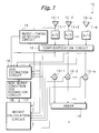
- Fig. 1 schematically illustrates a control apparatus for controlling an array antenna 10 having a plurality of antenna elements 10-1 to 10-m as a preferred embodiment according to the present invention.
- reference numerals 11-1 to 11-m denote A/D (Analog/Digital) converters for converting analog output signals from the antenna elements 10-1 to 10-m into digital signals
- 12 denotes a complexification circuit for producing complex signals of converted digital signals from the A/D converters 11-1 to 11-m
- 13-1 to 13-m denote multipliers for multiplying complex signals from the complexification circuit 12 by weights, respectively
- 14 denotes an adder for summing weighted output signals from the multipliers 13-1 to 13-m
- 15 denotes a burst-timing detection circuit
- 16 denotes a DOA estimation circuit
- 17 denotes a DOA estimation circuit for non-burst condition
- 18 denotes a weight calculation circuit.
- the output signals from the antenna elements 10-1 to 10-m are sampled at a predetermined sampling interval and converted into the digital signals in the respective A/D converters 11-1 to 11-m. Then, in the complexification circuit 12, the converted digital signals are separated into orthogonal components to produce the complex signals, respectively. In the multipliers 13-1 to 13-m, the respective complex signals are multiplied by the corresponding weights and then the weighted results are summed in the adder 14.
- the output signal from this reference element 10-1 is applied to the burst-timing detection circuit 15 to detect the timing of bursts by detecting the TDMA slot timing. Namely, whether it is a burst or an interval of bursts can be judged by detecting the TDMA slot timing.
- the detected burst timing is provided to the DOA estimation circuit 16.
- the output signals from the respective elements 10-1 to 10-m are also provided via the A/D converters 11-1 to 11-m and via the complexification circuit 12.
- the output signal from the DOA estimation circuit 16 is provided to the non-burst condition DOA estimation circuit 17 so as to estimate the DOA of the incident signal when no burst is received. If the array antenna is mounted on a mobile terminal, no burst may be temporarily received due to a hindrance. During such period of time, the non-burst condition DOA estimation circuit 17 estimates the DOA of the incident signal in accordance with the already estimated DOA. The configuration of this circuit 17 will be described in detail later.
- the DOA estimation circuit 16 needs at least one burst signal and an interval of bursts during which no burst signal exists, in order to obtain a DOA estimation result. Therefore, output time period of the DOA estimation result will be equal to the sum of one burst length and one interval of bursts.
- the signal indicating the estimated DOA is applied to the weight calculation circuit 18, and then weights are calculated based upon the estimated DOA by using the HA algorithm.
- a time interval with which the estimated DOA is provided to the weight calculation circuit 18 is equal to the output period of the DOA estimation result from the DOA estimation circuit 16, namely equal to the sum of one burst length and one interval of bursts.
- the weight calculation circuit 18 outputs the weights at a time interval equal to the sampling period and updates at the same time interval equal to the sum of one burst length and one burst interval. Namely, the weights are repeatedly held and updated with this time period.
- Fig. 2 illustrates an example of the DOA estimation circuit 16 according to the embodiment shown in Fig. 1.
- reference numeral 16a denotes a phase-difference calculation circuit for calculating phase differences between the received signals at the respective antenna elements 10-1 to 10-m
- 16b denotes a time-average calculation circuit for calculating average values of the calculated phase differences with respect to time
- 16c denotes a memory and subtraction circuit constituted by a memory for storing the time averaged values of the phase differences during a time period of burst and a subtraction circuit for calculating a difference between the time averaged values stored in the memory and input time averaged values during a time period of an interval of bursts
- 16d denotes a spatial averaging circuit.
- phase differences between the received signals of the respective antenna elements 10-1 to 10-m due to differences of the physical locations of the respective antenna elements are calculated based upon the following theory.
- the phase difference between the received signal of a reference element and the received signal of the adjacent element apart from the reference element by a distance d can be obtained from the product of a complex conjugate of the reference element output signal X 0 * and the adjacent element output signal X 1 as follows: where A 0 and A 1 are amplitudes of the reference element output signal and the adjacent element output signal, ⁇ is an angular frequency of the signal, ⁇ is the sum of initial phase and modulation phase of the signal, ⁇ is a wave length of the signal, and ⁇ is a incident angle of the signal.
- the angle of the incident signal can be relatively easily obtained by calculating the phase differences between the received signals of the antenna elements.
- the DOA cannot be detected by this method when the output signals of the elements include not only the desired signal but also interferers and so on.
- the following operations are executed in the circuits 16b and 16c.
- the output signals indicating the calculated phase differences from the phase-difference calculation circuit 16a are applied to the time-average calculation circuit 16b.
- burst timing information detected by the burst-timing detection circuit 15 is simultaneously applied.
- the circuit 16b starts the calculation of time average of the outputs from the circuit 16a when it knows that there exists a desired signal, namely a burst signal, based upon the applied burst timing information, and then outputs the computed result of time averaged values to the memory and subtraction circuit 16c when it detects that the burst period is ended (when it detects that it is during an interval of bursts) based upon the applied burst timing information.
- X 0 * X 1 A D 2 e j ⁇ D + A D A I e j[( ⁇ I - ⁇ D )t+(- ⁇ I - ⁇ D )+ ⁇ I ] +A D A I e j[( ⁇ D - ⁇ I )t + ( ⁇ D - ⁇ I )+ ⁇ D ] +A I 2 e j ⁇ I where A D and A I are amplitude, ⁇ D and ⁇ I are angular carrier frequency, and ⁇ D and ⁇ I are the sum of the initial phase and the modulation phase.
- the DOA of the desired signal can be known by calculating ⁇ D .
- the desired signal is TDMA burst signal but the interferer is continuous.
- terms of additive Gaussian noise are omitted for the simplicity of the explanation.
- the second and third terms can be varnished by time averaging in the time average calculation circuit 16b or a low pass filter. As a result, only the first and fourth terms will remain.
- the time-average calculation circuit 16b outputs the computed time averaged values to the memory and subtraction circuit 16c when it detects that the burst period is ended (when it detects that it is during an interval of bursts) based upon the applied burst timing information. Simultaneously to this, the circuit 16b once resets the data relating to the time-average calculation and starts new calculation of the time-averaged values. Then, when the circuit 16b detects that it is the time period of burst based upon the applied burst timing information, it outputs the time averaged values calculated during the interval of bursts to the following memory and subtraction circuit 16c. The output at this time indicates the phase differences due to signals other than the desired signal such as burst signal.
- the burst timing information detected by the burst-timing detection circuit 15 is also applied to the memory and subtraction circuit 16c as in the case of the time-average calculation circuit 16b.
- the circuit 16b provides output representing the time averaged value of the phase differences during an interval of bursts at the start of burst, and provides output representing the time averaged values of the phase differences during burst at the end of the burst to the circuit 16c.
- the circuit 16c stores the received output once in the memory if the received output is that representing the time averaged values of the phase differences during burst at the end of the burst, and then subtracts the next received output at the start of burst, which represents the time averaged values of the phase differences during an interval of bursts, from the stored time averaged value. Since this calculation is equivalent to the subtraction of the equation (7) from the equation (5), phase differences of the desired signal can be obtained.
- angles of the incident signals are applied to the spatial averaging circuit 16d.
- the angles of the incident signals estimated by these equal spacing element pairs are applied to the spatial averaging circuit 16d to obtain spatial averages of the incident signal angles in order to improve the accuracy of the DOA estimation.
- the linear array antenna in general has a plurality of antenna elements aligned with equal spacing.
- each linear array antenna there exist not only the minimum spacing element pairs but also element pairs with spacings as much as integer multiples of the minimum spacing.
- the phase differences produced by the integer multiple spacing element pairs are the integer multiples of the phase difference produced by the minimum spacing element pair.
- the signal phase difference linearly varies in response to the spacing of the element pair. Therefore, in the spatial averaging circuit 16d, a linear regression line representing the relationship between the element spacing (distance of elements) and the phase difference is calculated by using all the phase difference information detected with respect to all the available element spacings. Since this regression line is equivalent to a set of amended values of phase difference information separately obtained for each element spacing by using the phase different information of all the available element spacings, the accuracy of the phase difference detection which may deteriorate due to lowered S/N can be improved by this calculation.
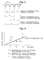
- averaging calculation in the circuit 16d will be explained in detail by using an example of a linear array antenna with four elements aligned with a spacing of a half wave length by using Figs. 3 and 4.
- three phase difference information A with the minimum spacing, two phase difference information B with the double minimum spacing, and one phase difference information C with the triple minimum spacing can be obtained.
- An average A AVE of the three phase difference information A and an average B AVE of the two phase difference information B are calculated.
- three data A AVE , B AVE and C can be obtained.
- a linear regression line can be obtained as shown in Fig. 4.
- the values on or adjacent to the line represent the aforementioned amended values of phase difference information separately obtained for each element spacing by using the phase different information of all the available element spacings.
- phase differences of the respective element spacings with respect to the reference element are provided as DOA estimation values (steering vectors) from the spatial averaging circuit 16d to the weight calculation circuit 18 via the non-burst condition DOA estimation circuit 17.
- reference numeral 17a denotes an adder for adding the input DOA estimation value with the value of the output signal from a multiplier 17d
- 17b denotes a delay element for delaying the output signal from the adder 17a
- 17c denotes a constant generator
- 17d denotes the multiplier for multiplying the value of the delayed output signal from the delay element 17b by a constant from the constant generator 17c, respectively.
- the non-burst condition DOA estimation circuit 17 with a feedback loop is provided.
- the DOA estimation value applied to the feedback loop is delayed by the delay element 17b by a time period equal to an interval of estimated value outputs, then multiplied by a predetermined constant from the constant generator 17c, and thereafter added to the next DOA estimation value.
- the predetermined constant from the generator 17c is adjusted to a value from 0 to 1 depending upon its transmission environment of radio wave.
Applications Claiming Priority (3)
| Application Number | Priority Date | Filing Date | Title |
|---|---|---|---|
| JP42877/97 | 1997-02-13 | ||
| JP04287797A JP3405111B2 (ja) | 1997-02-13 | 1997-02-13 | アレーアンテナの制御方法及び装置 |
| JP4287797 | 1997-02-13 |
Publications (2)
| Publication Number | Publication Date |
|---|---|
| EP0865099A2 true EP0865099A2 (de) | 1998-09-16 |
| EP0865099A3 EP0865099A3 (de) | 2000-11-08 |
Family
ID=12648280
Family Applications (1)
| Application Number | Title | Priority Date | Filing Date |
|---|---|---|---|
| EP98410009A Withdrawn EP0865099A3 (de) | 1997-02-13 | 1998-02-11 | Verfahren und Vorrichtung zur Steuerung einer Gruppenantenne |
Country Status (3)
| Country | Link |
|---|---|
| US (1) | US5854612A (de) |
| EP (1) | EP0865099A3 (de) |
| JP (1) | JP3405111B2 (de) |
Cited By (7)
| Publication number | Priority date | Publication date | Assignee | Title |
|---|---|---|---|---|
| EP0932218A2 (de) * | 1998-01-22 | 1999-07-28 | Matsushita Electric Industrial Co., Ltd. | Adaptives Gruppenantennensystem und mobiles Telekommunikationssystem damit |
| WO2002052677A1 (en) * | 2000-12-23 | 2002-07-04 | Nokia Corporation | Base station, base station module and method for direction of arrival estimation |
| CN102075226A (zh) * | 2009-11-24 | 2011-05-25 | 中兴通讯股份有限公司 | 一种双极化阵列系统中确定用户来波方向的方法及基站 |
| CN101686074B (zh) * | 2008-09-27 | 2012-09-26 | 中国移动通信集团公司 | 一种确定来波方向的方法及装置 |
| CN107450048A (zh) * | 2017-09-11 | 2017-12-08 | 成都信息工程大学 | 一种天线测角方法及系统 |
| CN111044969A (zh) * | 2019-12-03 | 2020-04-21 | 泰凌微电子(上海)有限公司 | 一种信号到达角估计方法、装置及计算机可读存储介质 |
| CN107515841B (zh) * | 2017-08-10 | 2021-02-23 | 中国科学院电子学研究所 | 计算电磁波波达角的方法 |
Families Citing this family (22)
| Publication number | Priority date | Publication date | Assignee | Title |
|---|---|---|---|---|
| US6127973A (en) * | 1996-04-18 | 2000-10-03 | Korea Telecom Freetel Co., Ltd. | Signal processing apparatus and method for reducing the effects of interference and noise in wireless communication systems |
| US5999800A (en) * | 1996-04-18 | 1999-12-07 | Korea Telecom Freetel Co., Ltd. | Design technique of an array antenna, and telecommunication system and method utilizing the array antenna |
| KR100229094B1 (ko) * | 1996-06-28 | 1999-11-01 | 최승원 | 수신신호에 대한 자기상관행렬의 최대고유치에 대응하는 고유벡터를 이용한 배열 안테나의 신호 처리 방법 |
| JP3497672B2 (ja) * | 1996-09-18 | 2004-02-16 | 株式会社東芝 | アダプティブアンテナおよびマルチキャリア無線通信システム |
| JP3391662B2 (ja) * | 1997-06-06 | 2003-03-31 | 松下電器産業株式会社 | アダプティブアレーアンテナ受信装置 |
| US6188915B1 (en) * | 1998-05-19 | 2001-02-13 | Harris Corporation | Bootstrapped, piecewise-asymptotic directivity pattern control mechanism setting weighting coefficients of phased array antenna |
| JP2000059278A (ja) * | 1998-08-03 | 2000-02-25 | Matsushita Electric Ind Co Ltd | 無線通信装置 |
| JP4169884B2 (ja) | 1999-09-24 | 2008-10-22 | 富士通株式会社 | 適応アンテナを用いた通信装置 |
| US6823174B1 (en) | 1999-10-11 | 2004-11-23 | Ditrans Ip, Inc. | Digital modular adaptive antenna and method |
| US20050088338A1 (en) * | 1999-10-11 | 2005-04-28 | Masenten Wesley K. | Digital modular adaptive antenna and method |
| JP2001324557A (ja) * | 2000-05-18 | 2001-11-22 | Sony Corp | 近距離場における信号発信源の位置をアレーアンテナを用いて推定する装置及び方法 |
| US6920192B1 (en) * | 2000-08-03 | 2005-07-19 | Lucent Technologies Inc. | Adaptive antenna array methods and apparatus for use in a multi-access wireless communication system |
| US7099384B1 (en) * | 2000-09-01 | 2006-08-29 | Qualcomm, Inc. | Method and apparatus for time-division power assignments in a wireless communication system |
| JP2002135185A (ja) * | 2000-10-19 | 2002-05-10 | Hitachi Kokusai Electric Inc | 受信機 |
| EP1220475A3 (de) * | 2000-12-25 | 2003-11-19 | Kabushiki Kaisha Toshiba | Mobiles Endstellengerät mit Gruppenantenne |
| US6930637B2 (en) * | 2001-11-15 | 2005-08-16 | Texas Instruments Incorporated | Method and apparatus for high resolution tracking via mono-pulse beam-forming in a communication system |
| JP4116624B2 (ja) | 2003-03-11 | 2008-07-09 | 富士通株式会社 | 無線装置 |
| WO2006067857A1 (ja) | 2004-12-24 | 2006-06-29 | Fujitsu Limited | 到来方向推定装置及びプログラム |
| JP4138825B2 (ja) * | 2006-07-26 | 2008-08-27 | 株式会社東芝 | ウェイト算出方法、ウェイト算出装置、アダプティブアレーアンテナ、及びレーダ装置 |
| US9121943B2 (en) * | 2011-05-23 | 2015-09-01 | Sony Corporation | Beam forming device and method |
| JP6397383B2 (ja) * | 2015-08-07 | 2018-09-26 | 日本電信電話株式会社 | 無線通信装置及び無線通信方法 |
| WO2022229386A1 (en) | 2021-04-30 | 2022-11-03 | Provizio Limited | Mimo radar using a frequency scanning antenna |
Citations (2)
| Publication number | Priority date | Publication date | Assignee | Title |
|---|---|---|---|---|
| WO1996029836A1 (de) * | 1995-03-20 | 1996-09-26 | Siemens Aktiengesellschaft | Mobilfunkfeststation mit veränderbarer antennencharakteristik |
| GB2307142A (en) * | 1995-11-08 | 1997-05-14 | Motorola Ltd | Steering an antenna in accordance with mobile location |
Family Cites Families (2)
| Publication number | Priority date | Publication date | Assignee | Title |
|---|---|---|---|---|
| US5321410A (en) * | 1988-06-09 | 1994-06-14 | Southwest Research Institute | Adaptive doppler DF system |
| US5274386A (en) * | 1992-06-17 | 1993-12-28 | General Electric Co. | Reduced hardware antenna beamformer |
-
1997
- 1997-02-13 JP JP04287797A patent/JP3405111B2/ja not_active Expired - Fee Related
-
1998
- 1998-02-09 US US09/020,540 patent/US5854612A/en not_active Expired - Fee Related
- 1998-02-11 EP EP98410009A patent/EP0865099A3/de not_active Withdrawn
Patent Citations (2)
| Publication number | Priority date | Publication date | Assignee | Title |
|---|---|---|---|---|
| WO1996029836A1 (de) * | 1995-03-20 | 1996-09-26 | Siemens Aktiengesellschaft | Mobilfunkfeststation mit veränderbarer antennencharakteristik |
| GB2307142A (en) * | 1995-11-08 | 1997-05-14 | Motorola Ltd | Steering an antenna in accordance with mobile location |
Non-Patent Citations (2)
| Title |
|---|
| BELL K ET AL: "ADAPTIVE NULLING FOR MULTIPLE DESIRED SIGNALS BASED ON SIGNAL WAVEFORM ESTIMATION" PROCEEDINGS OF THE MILITARY COMMUNICATIONS CONFERENCE (MILCOM),US,NEW YORK, IEEE, vol. CONF. 11, 11 October 1992 (1992-10-11), pages 919-923, XP000356673 ISBN: 0-7803-0586-8 * |
| WAHLBERG B G ET AL: "Experimental and theoretical comparison of some algorithms for beamforming in single receiver adaptive arrays" IEEE TRANSACTIONS ON ANTENNAS AND PROPAGATION,US,IEEE INC. NEW YORK, vol. 39, no. 1, January 1991 (1991-01), pages 21-28, XP002137360 ISSN: 0018-926X * |
Cited By (12)
| Publication number | Priority date | Publication date | Assignee | Title |
|---|---|---|---|---|
| EP0932218A2 (de) * | 1998-01-22 | 1999-07-28 | Matsushita Electric Industrial Co., Ltd. | Adaptives Gruppenantennensystem und mobiles Telekommunikationssystem damit |
| EP0932218A3 (de) * | 1998-01-22 | 2000-12-06 | Matsushita Electric Industrial Co., Ltd. | Adaptives Gruppenantennensystem und mobiles Telekommunikationssystem damit |
| US6349218B1 (en) | 1998-01-22 | 2002-02-19 | Matsushita Electric Industrial Co., Ltd. | Adaptive array antenna system and mobile telecommunications system using the same |
| US6781543B2 (en) | 1998-01-22 | 2004-08-24 | Matsushita Electric Industrial Co., Ltd. | Adaptive array antenna system and mobile telecommunications system using the same |
| WO2002052677A1 (en) * | 2000-12-23 | 2002-07-04 | Nokia Corporation | Base station, base station module and method for direction of arrival estimation |
| US6847327B2 (en) | 2000-12-23 | 2005-01-25 | Nokia Corporation | Base station, base station module and method for direction of arrival estimation |
| CN101686074B (zh) * | 2008-09-27 | 2012-09-26 | 中国移动通信集团公司 | 一种确定来波方向的方法及装置 |
| CN102075226A (zh) * | 2009-11-24 | 2011-05-25 | 中兴通讯股份有限公司 | 一种双极化阵列系统中确定用户来波方向的方法及基站 |
| CN107515841B (zh) * | 2017-08-10 | 2021-02-23 | 中国科学院电子学研究所 | 计算电磁波波达角的方法 |
| CN107450048A (zh) * | 2017-09-11 | 2017-12-08 | 成都信息工程大学 | 一种天线测角方法及系统 |
| CN111044969A (zh) * | 2019-12-03 | 2020-04-21 | 泰凌微电子(上海)有限公司 | 一种信号到达角估计方法、装置及计算机可读存储介质 |
| CN111044969B (zh) * | 2019-12-03 | 2022-02-11 | 泰凌微电子(上海)股份有限公司 | 一种信号到达角估计方法、装置及计算机可读存储介质 |
Also Published As
| Publication number | Publication date |
|---|---|
| JPH10229307A (ja) | 1998-08-25 |
| US5854612A (en) | 1998-12-29 |
| JP3405111B2 (ja) | 2003-05-12 |
| EP0865099A3 (de) | 2000-11-08 |
Similar Documents
| Publication | Publication Date | Title |
|---|---|---|
| US5854612A (en) | Method and apparatus for controlling array antenna | |
| EP1043801B1 (de) | Adaptives Gruppenantennensystem | |
| US5473333A (en) | Apparatus and method for adaptively controlling array antenna comprising adaptive control means with improved initial value setting arrangement | |
| Godara | Application of antenna arrays to mobile communications. II. Beam-forming and direction-of-arrival considerations | |
| EP1361678B1 (de) | Dispositif de recherche de voie, récepteur et emetteur radio utilisant un dispositif d'antenne à faisceau directionnel | |
| US5218359A (en) | Adaptive array antenna system | |
| US7228244B2 (en) | Method and apparatus for direction-of-arrival tracking and their application to beamforming at base-station | |
| US6317612B1 (en) | Method for estimating spatial parameters of transmission channels by estimating a spatial covariance matrix | |
| US7117016B2 (en) | Adaptive antenna base station apparatus | |
| EP0602615B1 (de) | Nebenkeulenkompensation und Diversityempfang mit einer einzigen Gruppe von Hilfsantennen | |
| US7006042B2 (en) | Antenna array system, method of controlling the directivity pattern thereof, and mobile terminal | |
| US6411257B1 (en) | Antenna angle-of-arrival estimation using uplink weight vectors | |
| Lee et al. | Robust adaptive array beamforming for cyclostationary signals under cycle frequency error | |
| EP0837340B1 (de) | Schätzer der Richtung des Nutzsignals | |
| JP2000147083A (ja) | 到来角測定方法及び到来角測定器 | |
| JP3017400B2 (ja) | アレーアンテナの制御方法及び制御装置 | |
| JP3438527B2 (ja) | 信号波到来角度推定装置及びアレーアンテナ制御装置 | |
| Swindlehurst et al. | Using least squares to improve blind signal copy performance | |
| JP4576742B2 (ja) | 送受信周波数分割多重無線装置 | |
| EP0096144B1 (de) | System zur Unterdrückung von absichtlichen Störungen denen eine phasengesteuerte Monopuls-Radarantennenanordnung ausgesetzt ist | |
| KR20020041558A (ko) | 이동통신 시스템에서 입사각 추정을 이용한 빔 형성 장치및 그 방법 | |
| US7487068B2 (en) | Interference eliminating method in adaptive array system and array processing device | |
| JP2932380B1 (ja) | 干渉波検出回路 | |
| JP2001044739A (ja) | アダプティブアレイ受信方式及びアダプティブアレイ受信装置 | |
| JP4056655B2 (ja) | アダプティブアンテナ及びアンテナ指向性制御方法 |
Legal Events
| Date | Code | Title | Description |
|---|---|---|---|
| PUAI | Public reference made under article 153(3) epc to a published international application that has entered the european phase |
Free format text: ORIGINAL CODE: 0009012 |
|
| AK | Designated contracting states |
Kind code of ref document: A2 Designated state(s): DE FR GB |
|
| AX | Request for extension of the european patent |
Free format text: AL;LT;LV;MK;RO;SI |
|
| PUAL | Search report despatched |
Free format text: ORIGINAL CODE: 0009013 |
|
| AK | Designated contracting states |
Kind code of ref document: A3 Designated state(s): AT BE CH DE DK ES FI FR GB GR IE IT LI LU MC NL PT SE |
|
| AX | Request for extension of the european patent |
Free format text: AL;LT;LV;MK;RO;SI |
|
| RIC1 | Information provided on ipc code assigned before grant |
Free format text: 7H 01Q 3/26 A, 7G 01S 3/16 B, 7G 01S 3/28 B, 7H 04Q 7/36 B |
|
| 17P | Request for examination filed |
Effective date: 20001215 |
|
| AKX | Designation fees paid |
Free format text: DE FR GB |
|
| 17Q | First examination report despatched |
Effective date: 20050324 |
|
| GRAP | Despatch of communication of intention to grant a patent |
Free format text: ORIGINAL CODE: EPIDOSNIGR1 |
|
| STAA | Information on the status of an ep patent application or granted ep patent |
Free format text: STATUS: THE APPLICATION IS DEEMED TO BE WITHDRAWN |
|
| 18D | Application deemed to be withdrawn |
Effective date: 20060828 |