EP0864456B1 - Rückschlagventil für Einfüllstutzen eines Kraftstofftanks zur Vermeidung von Kraftstoffleckagen - Google Patents
Rückschlagventil für Einfüllstutzen eines Kraftstofftanks zur Vermeidung von Kraftstoffleckagen Download PDFInfo
- Publication number
- EP0864456B1 EP0864456B1 EP19980104142 EP98104142A EP0864456B1 EP 0864456 B1 EP0864456 B1 EP 0864456B1 EP 19980104142 EP19980104142 EP 19980104142 EP 98104142 A EP98104142 A EP 98104142A EP 0864456 B1 EP0864456 B1 EP 0864456B1
- Authority
- EP
- European Patent Office
- Prior art keywords
- fuel
- annular
- seal member
- valve seat
- valve
- Prior art date
- Legal status (The legal status is an assumption and is not a legal conclusion. Google has not performed a legal analysis and makes no representation as to the accuracy of the status listed.)
- Expired - Lifetime
Links
Images

Classifications
-
- B—PERFORMING OPERATIONS; TRANSPORTING
- B60—VEHICLES IN GENERAL
- B60K—ARRANGEMENT OR MOUNTING OF PROPULSION UNITS OR OF TRANSMISSIONS IN VEHICLES; ARRANGEMENT OR MOUNTING OF PLURAL DIVERSE PRIME-MOVERS IN VEHICLES; AUXILIARY DRIVES FOR VEHICLES; INSTRUMENTATION OR DASHBOARDS FOR VEHICLES; ARRANGEMENTS IN CONNECTION WITH COOLING, AIR INTAKE, GAS EXHAUST OR FUEL SUPPLY OF PROPULSION UNITS IN VEHICLES
- B60K15/00—Arrangement in connection with fuel supply of combustion engines or other fuel consuming energy converters, e.g. fuel cells; Mounting or construction of fuel tanks
- B60K15/03—Fuel tanks
- B60K15/04—Tank inlets
-
- F—MECHANICAL ENGINEERING; LIGHTING; HEATING; WEAPONS; BLASTING
- F16—ENGINEERING ELEMENTS AND UNITS; GENERAL MEASURES FOR PRODUCING AND MAINTAINING EFFECTIVE FUNCTIONING OF MACHINES OR INSTALLATIONS; THERMAL INSULATION IN GENERAL
- F16K—VALVES; TAPS; COCKS; ACTUATING-FLOATS; DEVICES FOR VENTING OR AERATING
- F16K15/00—Check valves
- F16K15/02—Check valves with guided rigid valve members
- F16K15/03—Check valves with guided rigid valve members with a hinged closure member or with a pivoted closure member
- F16K15/033—Check valves with guided rigid valve members with a hinged closure member or with a pivoted closure member spring-loaded
-
- Y—GENERAL TAGGING OF NEW TECHNOLOGICAL DEVELOPMENTS; GENERAL TAGGING OF CROSS-SECTIONAL TECHNOLOGIES SPANNING OVER SEVERAL SECTIONS OF THE IPC; TECHNICAL SUBJECTS COVERED BY FORMER USPC CROSS-REFERENCE ART COLLECTIONS [XRACs] AND DIGESTS
- Y10—TECHNICAL SUBJECTS COVERED BY FORMER USPC
- Y10T—TECHNICAL SUBJECTS COVERED BY FORMER US CLASSIFICATION
- Y10T137/00—Fluid handling
- Y10T137/7722—Line condition change responsive valves
- Y10T137/7837—Direct response valves [i.e., check valve type]
- Y10T137/7898—Pivoted valves
- Y10T137/7901—Valve head movably connected for accommodation to seat
-
- Y—GENERAL TAGGING OF NEW TECHNOLOGICAL DEVELOPMENTS; GENERAL TAGGING OF CROSS-SECTIONAL TECHNOLOGIES SPANNING OVER SEVERAL SECTIONS OF THE IPC; TECHNICAL SUBJECTS COVERED BY FORMER USPC CROSS-REFERENCE ART COLLECTIONS [XRACs] AND DIGESTS
- Y10—TECHNICAL SUBJECTS COVERED BY FORMER USPC
- Y10T—TECHNICAL SUBJECTS COVERED BY FORMER US CLASSIFICATION
- Y10T137/00—Fluid handling
- Y10T137/7722—Line condition change responsive valves
- Y10T137/7837—Direct response valves [i.e., check valve type]
- Y10T137/7898—Pivoted valves
- Y10T137/7903—Weight biased
Definitions
- This invention generally relates to sealing apparatus for motor vehicle fuel tanks and, more particularly, to a fuel tank filler pipe check valve for preventing unwanted discharge of liquid fuel and fuel vapor into the atmosphere when the fuel cap is removed.
- Automotive fuel tanks are refuelled by means of a filler pipe that carries a detachable cap at its open end.
- This detachable cap is customarily designed to seal the open end of the filler pipe when it is installed.
- the gas cap is not properly installed after refuelling or forgotten altogether.
- the fill pipe is essentially open. This is an undesirable situation for many reasons particularly since it can effect the unwanted discharge of liquid fuel and fuel vapors into the atmosphere. Without some sort of device, such as, for example, a warning light on the dashboard of the vehicle, the operator would not be aware that the cap is not in place. Therefore, the unwanted discharge will continue unabated until discovered by the vehicle operator.
- the check valve according to DE 34 32 873 A1 comprises a flap element, which is connected to a hinge member and spring biased towards a stop element defining a stop position.
- the preamble of claim 1 is based on DE-3 432 873 A1.
- the flap element pivotally moves to an open position and fuel can stream through the fuel filler pipe.
- a check valve according to claim 1 including a seal door which is normally spring biased towards a closed position but which is responsive to a flow of fuel for displacing to an open position to allow fuel to pass in a first direction and for thereafter preventing passage of liquid fuel or fuel vapors in a second direction.
- the check valve is disposed at a lower end or midstream of a fuel tank filler pipe.
- the check valve includes an annular housing having a concentric annular valve seat portion including a frustoconical valve seat facing toward the lower end of the filler pipe.
- a seal door attached to a hinge member is resiliently biased toward engagement with the valve seat by a spring member leading to a sealed closure of the fuel filler pipe.
- the inflow of fuel overcomes the bias of the spring member which causes the seal door to displace to an open position to allow passage of fuel to the fuel tank.
- the seal door is returned to a closed position under the bias of the spring member in the absence of the inflowing fuel to prevent liquid fuel and fuel vapor from discharging into the atmosphere.
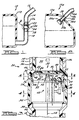
- a vehicle fuel system 10 including a fuel tank 12, a filler pipe 14 having an upper end or inlet 16 and a lower end or outlet 18 separated from the upper end 16 by a check valve 20.
- the vehicle fuel system 10 is a bottom fill system of a known type.
- the check valve 20 in FIG. 1 in a closed position seals the fuel tank 12 from the upper end 16 of the filler pipe 14.
- the check valve 20 displaces to an open position to allow filling of the fuel tank 12 with fuel in response to a predetermined pressure of inflowing fuel across the seal door 22.
- the check valve 20 includes an annular housing 24 defined between a pair of oppositely extending neck portions 26, 28 inserted within the upper and lower ends 16, 18 of the filler pipe 14 respectively.
- an alternate vehicle fuel system 10a including a fuel tank 12a, a filler pipe 14a having an upper end or inlet 16a and a lower end or outlet 18a coupled to the fuel tank 12a with a check valve 20a.
- the fuel system is a top fill system of a known type.
- the check valve 20a includes a sleeve 30 extending from the interior of the fuel tank 12a and inserted within the lower end 18a of the filler pipe 14a.
- the check valve 20a in FIG. 2 in a closed position seals the fuel tank 12a from the filler pipe 14a.
- the check valve 20a displaces to an open position to allow filling of the fuel tank 12a with fuel in response to a predetermined pressure of inflowing fuel across the seal door 22a.
- the check valve 20a includes only one neck portion 26a extending in a first direction from the annular housing 24a.
- FIG. 3 the check valve 20 of FIG. 1 is shown in greater detail mounted within the filler pipe 14 to open and close a filler pipe flow path 32 in the manner of a trap door.
- the check valve 20 hereinafter, one skilled in the art will appreciate that the following description is also applicable to the check valve 20a.
- the check valve 20 in the illustrative embodiment includes a two-piece assembly having a first cup-like insert 34 which fits axially into the filler pipe upper end 16, sealed at the interface 36 with an annular seal or filler pipe crimp and a second cup-like insert 38 which fits axially into the filler pipe lower end 18, sealed at the interface 40 with an annular seal or filler pipe crimp.
- the first insert 34 is abuttingly secured to the second insert 38, to define the annular housing 24 therebetween.
- the two piece construction of the check valve 20 and the resulting annular housing 24 permits the mounting of the seal door assembly 42 within the annular housing 24 along a central axis 44.
- the first insert 34 includes a concentric annular valve seat portion 46 including a frustoconical annular valve seat 48 facing in a direction toward the lower end 18 of the filler pipe 14.
- the first insert 34 also includes a plurality of radially extending recesses 50 axially spaced apart from the concentric annular valve seat portion 46. Although the plurality of recesses 50 are depicted, it should be noted that a radial extending annular groove may also be employed within the annular housing 24 with similar results.
- the first insert 34 is a molded plastic insert which carries the seal door assembly 42.
- the seal door assembly 42 includes an annular ring 52 supporting the seal door 22 within the annular housing 24. As illustrated, the annular ring 52 has a diameter equal to or slightly less than an inside diameter of the annular housing 24.
- the annular ring 52 is suspended from a plurality of vertical posts 54 extending upwardly from the annular ring 52, each post 54 including a radially extending tab 56 at a distal end thereof circumferentially engaging the annular recesses 50.
- the seal door 22 is pivotally or hingedly mounted via a hinge member 58 to the annular ring 52 for rotating between a closed position and an open position thereabout.
- the hinge member 58 includes a first radially extending arm 60 journally secured about a pivot pin 62 held in place on a cubical ear projection 64 formed integrally with the annular ring 52 radially offset from the axis 44.
- the first arm 60 is coupled to a second axially extending arm 66 downwardly projecting from the seal door 22 positioned relative to the seal door 22 such that the spring closing force is applied to the center of the seal door 22.
- the second arm 66 is preferably cylindrically shaped to minimize turbulence of the fuel flow therearound when the seal door 22 is in an open position. Also, since the pressure of inflowing fuel is borne by the seal door 22 and hinge member 58 in an open position, it is preferred that the coupling between the first arm 60 and second arm 66 include vertical or linear play relative to the pivot pin 62. This allows the seal door 22 to "float" as well as pivot when opened or closed, helping align the seal door 22 with the annular valve seat 48 and improving its seal. As seen in FIG. 4, to accomplish this, the first arm 60 includes a bifurcated end 68 defining a slot 70 for slidingly engaging the second arm 66.
- a coil spring 72 is disposed about the pivot pin 62 and is held or fastened at one end 74 to an opening 76 in an ear 78 (FIG. 3) projecting from the first arm 60.
- the spring 72 is metal.
- the free end 80 of the spring 72 frictionally engages an interior surface of the annular housing 24 to enable loading thereof when the seal door 22 is pivoted.
- the spring 72 normally biases the seal door 22 to the closed position against the annular valve seat 48 as illustrated in FIG. 3.
- the bias of the spring 72 is overcome by inflowing fuel enabling the seal door 22 to rotate to an open position as depicted in phantom in FIG. 3.
- the illustrated embodiment of the seal door 22 includes a flexible member 82 and a rigid member 84. It is preferred that the upper member 82 be interposed within the rigid members 84 by overmolding. When assembled, upper member 82 and lower member 84 preferably define a plastic plate portion 86 supporting a radially extending rubber flange portion 88.
- the plate portion 86 is centered within and extends upwardly towards the filler pipe 14 to a point below the annular valve seat 48.
- the diameter of the plate portion 86 is slightly less than that of the aperture 90 within the neck portion 26 of the first insert 34.
- the flange portion 88 is of a diameter greater than the aperture 90 but less than that of the annular housing 24 so that its upper surface comes into contact with the annular valve seat 48 in the closed position.
- the spring closing force on the seal door 22 is applied at 92 which is centered relative to the annular housing 24 and annular valve seat 48 to apply even sealing force about the periphery of the seal door 22.
- Inflow of fuel through the filler pipe 14 and against the seal door 22 pivots the seal door 22 about the pivot pin 62, simultaneously applying torque to the spring 72.
- the seal door 22 is displaced to an open position, shown in phantom in FIG. 3, to allow fuel to pass to the fuel tank 12.
- the spring 72 via the end 74 forces the seal door 22 back to the closed position to prevent outflow of liquid fuel and fuel vapor from the fuel tank 12.
- the strength of the spring 72 is selected to yield to a predetermined pressure of fuel from the upper end 16 of the filler pipe 14 which forces the flange portion 88 downwardly off the annular valve seat 48 to open the flow path 32 through the filler pipe 14 to the fuel tank 12.
- a predetermined pressure of fuel from the upper end 16 of the filler pipe 14 which forces the flange portion 88 downwardly off the annular valve seat 48 to open the flow path 32 through the filler pipe 14 to the fuel tank 12.
- approximately one inch of non-flowing fuel within the filler pipe upper end 16 will overcome the bias of the spring 72 and displace the seal door 22.
- this may be modified as desired.
- the seal door 22a has a generally plano-convex or airfoil-type shape which shifts the center of gravity of the seal door 22a to a geometrically centered position. This causes the door seal 22a to self-center upon returning to a closed position such that the flange portion 88 evenly mates with the annular valve seat 48 about its periphery.
- the airfoil configuration of the seal door 22a depicted in FIG. 6 establishes a pressure differential between the top surface and bottom surface thereof as fuel flows therearound. The pressure differential holds the seal door 22a in an open position vertically orientated relative to the fuel flow when fuel is flowing through the filler pipe. This reduces vibrations of the seal door 22a when in an open position.
- the embodiment illustrated in FIG. 6 also includes an annular ring 52a which is directly seated within the annular groove 50a.
- the annular ring 52a is preferably a resilient split-type snap ring having a diameter in a relaxed state slightly greater than an inside diameter of the housing.
- the ring 52a is inserted into the groove 50a by pinching it outboard of the split to decrease its diameter and inserting it into the annular housing 24.
- the resiliency of the ring 52a forces it radially outward and into engaging relation with the groove 50a.
- the axial spacing of the groove 52a relative the valve seat 48 may be decreased over the first embodiment since the posts 54 have been omitted.
- a check valve is disposed at a lower end or midstream of a fuel tank filler pipe such that the dispenser nozzle does not come into contact with the seal door when it is inserted within the filler pipe.
- the fluid force of inflowing fuel pivots the seal door about the pivot pin to an open position against the force of the spring. This opens the fluid flow path through the filler pipe to the fuel tank.
- the seal door is returned to a closed position under the force of the spring to prevent liquid fuel and fuel vapor from discharging from the fuel tank when the fuel cap or filler pipe are damaged or absent.
Claims (8)
- Rückschlagventil (20) zur sicheren Abdichtung eines Krafttanks (12) gegen das Ausfließen von Kraftstoff aus dem Tank (12), während die Einströmung von Kraftstoff in den Tank (12) möglich ist, wobei der Tank (12) einen Kraftstoffeinfüllstutzen (14) mit einem Kraftstoffeinlassende (16) und einem Tankverbindungsende (18) aufweist, wobei das Rückschlagventil (20) aufweist:dadurch gekennzeichnet, dassein ringförmiges Gehäuse (24) mit einer Achse (44), wobei das ringförmige Gehäuse (24) einen konzentrischen ringförmigen. Ventilsitzteil (46) mit einem Ventilsitz (48) enthält, welches in einer Richtung zum Tankende (18) des Krafstoffeinfüllstutzens (14) weist;ein Scharnierteil (58) in axialem Abstand vom konzentrischen ringförmigen Ventilsitz (48); undein Dichtungsteil (22), das am Scharnierteil (58) befestigt ist, wobei das Dichtungsteil (22) gegen den Eingriff mit dem Ventilsitz (48) durch ein Federorgan (72) elastisch belastet ist, wobei das Dichtungsteil (22) auf eine Kraftstoffströmung anspricht, um das Durchtreten von Kraftstoff in einer ersten Richtung zu ermöglichen, und anschließend den Durchtritt von Kraftstoff in einer zweiten Richtung abzudichten,
der Ventilsitz (48) allgemein eine Kegelstumpfform besitzt und dass
das Dichtungsteil (22) einen Gummiflansch (88) aufweist, der sich allgemein radial von diesem erstreckt. - Ventil (20) nach Anspruch 1, bei welchem das Dichtungsteil (22) am Scharnierteil (58) über einen axial verlaufenden Arm (66) befestigt ist, welcher mit einem radial verlaufenden Arm (60) verbunden ist.
- Ventil (20) nach Anspruch 1, bei welchem das Federorgan (72) eine metallische Schraubenfeder ist.
- Ventil (20) nach Anspruch 1, bei welchem das ringförmige Gehäuse (24) eine Innenwand mit einer Anzahl von radial verlaufenden Vertiefungen (50) enthält, und bei welchem das Scharnierteil (58) an der Wand über Ansätze (56) befestigt ist, die sich in die radial verlaufenden Vertiefungen (50) erstrecken.
- Ventil (20) nach Anspruch 1, bei welchem das ringförmige Gehäuse (24) aus Kunststoff gespritzt ist, wobei der Ventilsitz (48) einstückig damit geformt ist.
- Ventil (20) nach Anspruch 1, dadurch gekennzeichnet, dass es aufweist:wobei der ringförmige Gehäuseteil (24) eine Anzahl von radial verlaufenden Vertiefungen (50) enthält, die in einer Innenwand desselben geformt sind;wenigstens einen becherartigen Einsatz (34),(38), der einen Stutzenteil (26), (28) aufweist, welcher vom ringförmigen Gehäuseteil (24) durch den Ventilsitz (48) mit Kegelstumpfform getrennt ist;
einen Kreisring (52) mit einer Anzahl von vertikal verlaufenden Stützen (54), die von demselben nach oben stehen, wobei jede Stütze (54) einen radial verlaufenden Ansatz (56) aufweist, der von einem distalen Ende desselben absteht, wobei die Ansätze (56) in die Vertiefungen (50) eingreifen, um den Kreisring (52) daran aufzuhängen;
wobei das Dichtungsorgan (22) mit dem Kreisring über das Scharnierteil (58) drehbar gekoppelt ist zur Ausführung einer Bewegung zwischen der geschlossenen Stellung, in der das Dichtungsorgan (22) am Ventilsitz (48) anliegt, um das Ausströmen von flüssigem Kraftstoff und Kraftstoffdampf aus dem Kraftstofftank (12) zu verhindern, sowie der geöffneten Stellung, in der das Dichtungsorgan (22) vom Ventilsitz (48) entfernt ist, um das Einströmen von Kraftstoff in den Kraftstofftank (12) durch den Einfüllstutzen (14) zu ermöglichen;
das Dichtungsorgan (22) einen festen Plattenteil (84),(86) aufweist, welcher den radial abstehenden Flanschteil (82),(88) stützt, der flexibel ist, wobei der Flanschteil (82),(88) einen etwas geringeren Durchmesser besitzt als der Innendurchmesser des Stutzenteils (26),(28) und einen etwas größeren als ein Innendurchmesser des ringförmigen Gehäuseteils (24), so dass eine Oberfläche des Flanschteils (82),(88) am Ventilsitz (48) angreift, wenn das Dichtungsorgan (22) sich in der geschlossenen Stellung befindet;
wobei das Scharnierteil (58) einen ersten axial verlaufenden Arm (66) aufweist, der vom Dichtungsorgan (22) nach unten steht, sowie einen zweiten radial abstehenden Arm (60), der am ersten Arm (66) an einem gegabelten ersten Ende (68) gleitend angreift und mit dem Kreisring (52) an einem zweiten Ende über einen Schwenkzapfen (62) drehbar gekoppelt ist; und
wobei ein Schraubenfederorgan (72) mit einem ersten Ende (74) mit dem Scharnierteil (58) gekoppelt ist, das normalerweise das Dichtungsorgan (22) in die geschlossene Stellung drückt und einer vorbestimmten Einströmung von Kraftstoff nachgibt, um zu ermöglichen, dass das Dichtungsorgan (22) sich in die geöffnete Stellung über das Scharnierteil (58) verschwenkt. - Ventil (20) nach Anspruch 6, bei welchen die Anzahl von Vertiefungen (50) miteinander verbunden ist, um eine radial verlaufende Ringnut (50a) in der Innenwand des ringförmigen Gehäuses (24) zu bilden.
- Ventil (20) nach Anspruch 6, bei welchem der Kreisring (52) einen elastisch gespaltenen Schnappring aufweist, der direkt in der Ringnut (50a) sitzt).
Applications Claiming Priority (2)
| Application Number | Priority Date | Filing Date | Title |
|---|---|---|---|
| US815155 | 1997-03-11 | ||
| US08/815,155 US6026853A (en) | 1997-03-11 | 1997-03-11 | Fuel tank filler neck check valve |
Publications (3)
| Publication Number | Publication Date |
|---|---|
| EP0864456A2 EP0864456A2 (de) | 1998-09-16 |
| EP0864456A3 EP0864456A3 (de) | 1999-08-18 |
| EP0864456B1 true EP0864456B1 (de) | 2004-07-07 |
Family
ID=25217030
Family Applications (1)
| Application Number | Title | Priority Date | Filing Date |
|---|---|---|---|
| EP19980104142 Expired - Lifetime EP0864456B1 (de) | 1997-03-11 | 1998-03-09 | Rückschlagventil für Einfüllstutzen eines Kraftstofftanks zur Vermeidung von Kraftstoffleckagen |
Country Status (3)
| Country | Link |
|---|---|
| US (1) | US6026853A (de) |
| EP (1) | EP0864456B1 (de) |
| DE (1) | DE69824906D1 (de) |
Families Citing this family (20)
| Publication number | Priority date | Publication date | Assignee | Title |
|---|---|---|---|---|
| US6026855A (en) * | 1997-12-16 | 2000-02-22 | Itt Manufacturing Enterprises, Inc. | Fuel tank one-way flow valve quick connector |
| ATE269797T1 (de) * | 1998-11-28 | 2004-07-15 | Raviv Prec Injection Molding | Kraftstofftankanordnung für kraftfahrzeug |
| KR100793217B1 (ko) * | 1999-10-22 | 2008-01-10 | 넥스트넷 와이어리스 인크. | 프레임된 하향링크 및 프레임되지 않은 상향링크로서 데이터 패킷을 전달하기 위한 시스템 및 방법 |
| DE10040310C2 (de) * | 2000-08-17 | 2002-11-21 | Alfmeier Praez Ag | Füllstandsbegrenzungsventil |
| US6405767B1 (en) | 2000-10-03 | 2002-06-18 | General Motors Corporation | Fuel fill pipe assembly with vortexing vanes |
| US6289945B1 (en) | 2000-10-06 | 2001-09-18 | General Motors Corporation | Fuel fill assembly with vent passage |
| DE10304364A1 (de) * | 2003-02-04 | 2004-08-12 | J. Eberspächer GmbH & Co. KG | Drosselanordnung sowie Abgasanlage mit einer derartigen Drosselanordnung |
| DE10331073B4 (de) * | 2003-07-09 | 2007-07-12 | Alfmeier Präzision AG Baugruppen und Systemlösungen | Fahrzeugtank mit einem Einfüllrohr |
| EP1518739A3 (de) * | 2003-09-29 | 2005-11-30 | Alfmeier Präzision Ag Baugruppen und Systemlösungen | Kraftfahrzeugtank mit Entlüftungssystem |
| US7147001B2 (en) | 2004-03-26 | 2006-12-12 | Stant Manufacturing Inc. | Fuel-transfer system |
| US6968874B1 (en) | 2004-10-07 | 2005-11-29 | Martinrea Industries, Inc. | Capless automotive fueling system |
| US7757729B2 (en) * | 2005-12-29 | 2010-07-20 | Smith Gregory F | Filler tube assembly |
| US8622101B2 (en) * | 2005-12-29 | 2014-01-07 | David G. Smith | Filler tube assembly |
| FR2896568B1 (fr) * | 2006-01-26 | 2008-03-14 | Inergy Automotive Systems Res | Dispositif pour circuit de mise a l'air d'un reservoir a liquide et clapet integrant ledit dispositif |
| US8262042B2 (en) * | 2006-06-13 | 2012-09-11 | L.J. Star Incorporated | Retaining split ring with clamp |
| JP4730614B2 (ja) * | 2006-09-15 | 2011-07-20 | 豊田合成株式会社 | 燃料タンク用バルブ装置 |
| US8746479B2 (en) * | 2009-01-30 | 2014-06-10 | Neal L. Keefer | Method of closing a fuel tank with a pivotal door and seal |
| EP2818351B1 (de) * | 2013-06-26 | 2016-04-06 | Inergy Automotive Systems Research (Société Anonyme) | Verfahren und System zur Druckentlüftung eines Kraftfahrzeugkraftstofftanksystems |
| ES2699304T3 (es) | 2014-10-01 | 2019-02-08 | Sonoco Dev Inc | Estructura de recipiente con una abertura integrada y función de cierre |
| US11203477B2 (en) | 2015-10-30 | 2021-12-21 | Sonoco Development, Inc. | Integrated package opening feature |
Family Cites Families (34)
| Publication number | Priority date | Publication date | Assignee | Title |
|---|---|---|---|---|
| US1196405A (en) * | 1914-11-17 | 1916-08-29 | William Steeg | Valve. |
| US2048943A (en) * | 1934-04-21 | 1936-07-28 | Alfred N Munn | Check valve |
| US2482198A (en) * | 1944-09-05 | 1949-09-20 | Parker Appliance Co | Valve structure |
| US2503031A (en) * | 1947-01-21 | 1950-04-04 | Davidson Donald | Self-closing automobile gas cap |
| US2925825A (en) * | 1954-05-04 | 1960-02-23 | Stewart Warner Corp | High performance check valve |
| US2923317A (en) * | 1955-11-17 | 1960-02-02 | Crane Co | Swing check valve |
| US2913001A (en) * | 1956-12-27 | 1959-11-17 | Flight Refueling Inc | Check valve |
| US3060961A (en) * | 1960-09-19 | 1962-10-30 | Edwin E Conley | Pivoted valve structure |
| US3182951A (en) * | 1962-01-18 | 1965-05-11 | Kenneth L Spencer | Pivoted valve |
| US3331391A (en) * | 1964-06-01 | 1967-07-18 | Grinnell Corp | Check valve clapper construction |
| US3395727A (en) * | 1965-03-01 | 1968-08-06 | Anderson Greenwood & Co | Check valve |
| BE791878A (fr) * | 1971-11-26 | 1973-03-16 | Bryan Donkin Co Ltd | Perfectionnement aux clapets de non-retour |
| US3730216A (en) * | 1972-04-06 | 1973-05-01 | Ford Motor Co | Fuel tank insert for admitting preselected pump nozzles |
| US3911949A (en) * | 1973-12-03 | 1975-10-14 | Aero Tec Lab Inc | Safety fueling valve |
| US3937441A (en) * | 1975-02-21 | 1976-02-10 | Baumann Hans D | Rotary valve |
| US4164958A (en) * | 1977-11-03 | 1979-08-21 | Jenkins Brothers | Swing check valve |
| US4301833A (en) * | 1979-10-05 | 1981-11-24 | Donald Iii Robert A | Flow responsive safety valve |
| US4526216A (en) * | 1983-05-16 | 1985-07-02 | Yamaha Motor Corporation, U.S.A. | Unleaded fuel filling system for tanks without inlet pipe |
| DE3432873A1 (de) * | 1984-09-07 | 1985-08-08 | Daimler-Benz Ag, 7000 Stuttgart | Einfuellvorrichtung fuer kraftstoffbehaelter, insbesondere fuer kraftfahrzeuge |
| DE3602844C1 (de) * | 1986-01-30 | 1987-01-02 | Temtec Fahrzeugtechnik Entwicklungsgesellschaft Mbh | Blendenring |
| US4977936A (en) * | 1986-03-31 | 1990-12-18 | Stant Inc. | Filler neck sealing assembly |
| US4825902A (en) * | 1988-01-11 | 1989-05-02 | Halliburton Company | Flapper valve with protective hinge pin sleeve |
| DE3829948A1 (de) * | 1988-09-03 | 1990-03-15 | Freudenberg Carl Fa | Zapfpistolendichtung |
| US4982759A (en) * | 1988-12-20 | 1991-01-08 | Scaramucci John P | Swing check valve with secured cage |
| US4971103A (en) * | 1988-12-20 | 1990-11-20 | Scaramucci John P | Swing check valve with secured cage |
| US5042678A (en) * | 1990-07-20 | 1991-08-27 | Munguia Preston T | Fuel tank filler tube closure assembly |
| JP2512168Y2 (ja) * | 1991-02-15 | 1996-09-25 | オーエム工業株式会社 | 燃料タンクの逆流防止弁 |
| US5159953A (en) * | 1991-09-11 | 1992-11-03 | Om Industrial Co., Ltd. | Check valve apparatus for fuel tank |
| JPH0629921U (ja) * | 1992-09-29 | 1994-04-19 | オーエム工業株式会社 | 燃料タンクの逆流防止弁 |
| US5282497A (en) * | 1992-10-23 | 1994-02-01 | Allen Allison | Fuel delivery and vapor control system for controlling the release of fuel vapors from a vehicle fuel tank |
| US5322100A (en) * | 1993-01-27 | 1994-06-21 | Borg-Warner Automotive, Inc. | Fuel filler module |
| US5320147A (en) * | 1993-05-06 | 1994-06-14 | Ford Motor Company | Fuel filler pipe fill control module |
| US5431199A (en) * | 1993-11-30 | 1995-07-11 | Benjey, Robert P | Redundant seal for vehicle filler neck |
| US5568838A (en) * | 1994-09-23 | 1996-10-29 | Baker Hughes Incorporated | Bit-stabilized combination coring and drilling system |
-
1997
- 1997-03-11 US US08/815,155 patent/US6026853A/en not_active Expired - Lifetime
-
1998
- 1998-03-09 EP EP19980104142 patent/EP0864456B1/de not_active Expired - Lifetime
- 1998-03-09 DE DE69824906T patent/DE69824906D1/de not_active Expired - Lifetime
Also Published As
| Publication number | Publication date |
|---|---|
| DE69824906D1 (de) | 2004-08-12 |
| EP0864456A2 (de) | 1998-09-16 |
| US6026853A (en) | 2000-02-22 |
| EP0864456A3 (de) | 1999-08-18 |
Similar Documents
| Publication | Publication Date | Title |
|---|---|---|
| EP0864456B1 (de) | Rückschlagventil für Einfüllstutzen eines Kraftstofftanks zur Vermeidung von Kraftstoffleckagen | |
| EP1838546B1 (de) | Führungsbewegung eines deckellosen einfüllstutzenverschlusses | |
| US5660206A (en) | Fuel tank filler neck check valve | |
| US5431199A (en) | Redundant seal for vehicle filler neck | |
| US4986439A (en) | Cap for the filler neck of liquid containers | |
| EP1479554B1 (de) | Rückschlagventil für Kraftstoffeinfüllstutzen | |
| US4966299A (en) | Fuel assembly having a vapor vent with a hinged float valve | |
| US5027868A (en) | Vapor recovery systems | |
| US6945290B1 (en) | Check valve for use in filler tube vapor recirculation system and method of making same | |
| US5950655A (en) | Mechanical seal ORVR system and control valve | |
| US4724868A (en) | Cap with valve | |
| EP1642760A2 (de) | Dispositif d'aération d'un réservoir de carburant avec orifice d'interruption du remplissage à hauteur réglable | |
| US6612324B2 (en) | Fill limit vapor valve with variable vapor venting capability | |
| US5884958A (en) | Fuel filler assembly, particularly for a motor vehicle | |
| EP0900684A2 (de) | Entlüftunsventil für Benzindämpfe | |
| JP4151012B2 (ja) | 燃料タンク用チェックバルブを備える燃料給油管アセンブリ | |
| US6035906A (en) | Self-closing gas for automatic filling machines | |
| US6257287B1 (en) | Fuel fill pipe shut-off device | |
| JPH04236870A (ja) | 燃料蒸気逃がし弁 | |
| US5071018A (en) | Capless closure assembly for a fuel filler pipe | |
| EP3269577A1 (de) | Betankungsabschnittsstruktur eines kraftstofftanks | |
| US5950659A (en) | Vehicle fuel vapor vent valve | |
| JP3326561B2 (ja) | 弁本体を備える燃料タンクの保持構造の改良 | |
| US6283147B1 (en) | Non-return valve for a fuel tank | |
| JPH03121380A (ja) | リリーフ弁 |
Legal Events
| Date | Code | Title | Description |
|---|---|---|---|
| PUAI | Public reference made under article 153(3) epc to a published international application that has entered the european phase |
Free format text: ORIGINAL CODE: 0009012 |
|
| AK | Designated contracting states |
Kind code of ref document: A2 Designated state(s): AT BE CH DE DK ES FI FR GB GR IE IT LI LU MC NL PT SE |
|
| AX | Request for extension of the european patent |
Free format text: AL;LT;LV;MK;RO;SI |
|
| PUAL | Search report despatched |
Free format text: ORIGINAL CODE: 0009013 |
|
| AK | Designated contracting states |
Kind code of ref document: A3 Designated state(s): AT BE CH DE DK ES FI FR GB GR IE IT LI LU MC NL PT SE |
|
| AX | Request for extension of the european patent |
Free format text: AL;LT;LV;MK;RO;SI |
|
| RIC1 | Information provided on ipc code assigned before grant |
Free format text: 6B 60K 15/04 A |
|
| 17P | Request for examination filed |
Effective date: 20000209 |
|
| AKX | Designation fees paid |
Free format text: DE FR GB |
|
| 17Q | First examination report despatched |
Effective date: 20020430 |
|
| GRAP | Despatch of communication of intention to grant a patent |
Free format text: ORIGINAL CODE: EPIDOSNIGR1 |
|
| RAP1 | Party data changed (applicant data changed or rights of an application transferred) |
Owner name: BORGWARNER INC. |
|
| GRAS | Grant fee paid |
Free format text: ORIGINAL CODE: EPIDOSNIGR3 |
|
| GRAA | (expected) grant |
Free format text: ORIGINAL CODE: 0009210 |
|
| AK | Designated contracting states |
Kind code of ref document: B1 Designated state(s): DE FR GB |
|
| PG25 | Lapsed in a contracting state [announced via postgrant information from national office to epo] |
Ref country code: FR Free format text: LAPSE BECAUSE OF FAILURE TO SUBMIT A TRANSLATION OF THE DESCRIPTION OR TO PAY THE FEE WITHIN THE PRESCRIBED TIME-LIMIT Effective date: 20040707 |
|
| REG | Reference to a national code |
Ref country code: GB Ref legal event code: FG4D |
|
| REF | Corresponds to: |
Ref document number: 69824906 Country of ref document: DE Date of ref document: 20040812 Kind code of ref document: P |
|
| PG25 | Lapsed in a contracting state [announced via postgrant information from national office to epo] |
Ref country code: DE Free format text: LAPSE BECAUSE OF FAILURE TO SUBMIT A TRANSLATION OF THE DESCRIPTION OR TO PAY THE FEE WITHIN THE PRESCRIBED TIME-LIMIT Effective date: 20041008 |
|
| PG25 | Lapsed in a contracting state [announced via postgrant information from national office to epo] |
Ref country code: GB Free format text: LAPSE BECAUSE OF NON-PAYMENT OF DUE FEES Effective date: 20050309 |
|
| PLBE | No opposition filed within time limit |
Free format text: ORIGINAL CODE: 0009261 |
|
| STAA | Information on the status of an ep patent application or granted ep patent |
Free format text: STATUS: NO OPPOSITION FILED WITHIN TIME LIMIT |
|
| 26N | No opposition filed |
Effective date: 20050408 |
|
| EN | Fr: translation not filed | ||
| GBPC | Gb: european patent ceased through non-payment of renewal fee |
Effective date: 20050309 |