EP0863379B1 - Initiateur électro-pyrotechnique constitué autour d'un circuit imprimé complet - Google Patents
Initiateur électro-pyrotechnique constitué autour d'un circuit imprimé complet Download PDFInfo
- Publication number
- EP0863379B1 EP0863379B1 EP98400495A EP98400495A EP0863379B1 EP 0863379 B1 EP0863379 B1 EP 0863379B1 EP 98400495 A EP98400495 A EP 98400495A EP 98400495 A EP98400495 A EP 98400495A EP 0863379 B1 EP0863379 B1 EP 0863379B1
- Authority
- EP
- European Patent Office
- Prior art keywords
- circuit
- initiator
- initiator according
- electro
- pyrotechnic
- Prior art date
- Legal status (The legal status is an assumption and is not a legal conclusion. Google has not performed a legal analysis and makes no representation as to the accuracy of the status listed.)
- Expired - Lifetime
Links
Images


Classifications
-
- F—MECHANICAL ENGINEERING; LIGHTING; HEATING; WEAPONS; BLASTING
- F42—AMMUNITION; BLASTING
- F42B—EXPLOSIVE CHARGES, e.g. FOR BLASTING, FIREWORKS, AMMUNITION
- F42B3/00—Blasting cartridges, i.e. case and explosive
- F42B3/10—Initiators therefor
- F42B3/12—Bridge initiators
- F42B3/121—Initiators with incorporated integrated circuit
-
- F—MECHANICAL ENGINEERING; LIGHTING; HEATING; WEAPONS; BLASTING
- F42—AMMUNITION; BLASTING
- F42B—EXPLOSIVE CHARGES, e.g. FOR BLASTING, FIREWORKS, AMMUNITION
- F42B3/00—Blasting cartridges, i.e. case and explosive
- F42B3/10—Initiators therefor
- F42B3/18—Safety initiators resistant to premature firing by static electricity or stray currents
- F42B3/188—Safety initiators resistant to premature firing by static electricity or stray currents having radio-frequency filters, e.g. containing ferrite cores or inductances
Definitions
- the present invention relates to the field of pyrotechnic initiators and more specifically concerns an electro-pyrotechnic initiator intended for the automotive safety.
- Electro-pyrotechnic initiators are traditionally made from two pins conductive of electricity which are maintained by a overmolding of insulating material and the ends of which are connected to each other by a filament resistive heater which is enclosed in a pearl igniter made from a primary explosive such as lead trinitroresorcinate or styphnate lead and whose lower ends are connected to a source of electrical current.
- Such initiators can be used to initiate protective devices by airbag of occupants of a vehicle automotive, as explained in patent GB-A-2,019 198.
- Such electro-pyrotechnic initiators are widely used to build devices ignition of pyrotechnic gas generators intended to inflate protective cushions for occupants of a motor vehicle.
- a ferrite core like this is for example described in patents U-S-A-4,722,551, EP-A-0 512 682 and US-A-5 355 800.
- the resistive filament heater is sometimes replaced by a printed circuit having a resistive and heating part like this is, for example, described in patent application FR-A-2 704 944 or in its correspondent US-A-5 544 585.
- the support of the printed circuit can have the form of a thin parallelepiped map.
- these printed circuits generally have a topography complex that uses both sides of the support as described for example in patent EP-A-0 150 823.
- the object of the present invention is precisely to propose such an initiator by removing the pins and ferrite cores and integrating their functions in a simple PCB, unlike anything that has been done so far.
- the PCB holder will normally made from one of the insulating materials usually used to make such supports.
- the electromagnetic protection means of the initiator against stray currents can be consisting of at least one filter coil deposited on said circuit support.
- the filter coil can itself be printed on said circuit support and constitute with said electrical circuit a multilayer printed circuit.
- Said means of electromagnetic protection can still be made up of at least one capacitor deposited on said circuit support.
- the said electrical circuit and the said means of protection electromagnetic will be covered by a layer of insulating varnish.
- the circuit support covered or not by a layer of insulating varnish, will also be partially coated with an insulating overmold of so as to leave only the part of the support free circuit carrying the covered resistive heating element by the thermosensitive load.
- the charge thermosensitive is not itself at least partially maintained by the said overmolding, it will be advantageously protected by a fragmentable mask.
- the said circuit support has the form of a thin parallelepiped card with two opposite flat faces allows you to make electro-pyrotechnic initiators in which on each of the two flat faces of the circuit support is printed a separate circuit of conductive strips each including a resistive heating element covered by a thermosensitive load and means of electromagnetic protection. It is thus possible to constitute an initiator who presents, for a source single electric, two separate ignition heads and which is particularly reliable and safe.
- the invention also relates to an electro-pyrotechnic igniter characterized in that an initiator according to the invention is surrounded by a fragmentable cap containing powdered ignition powder.
- the invention finally relates to the use of a electro-pyrotechnic initiator according to the invention for cause the ignition of a pyrotechnic generator gas intended to inflate a protective cushion for occupant of a motor vehicle.
- the initiator may be used directly to switch on the load generator pyrotechnic when it is under form of grains or pellets, it will advantageously used via an igniter as described higher when the load is in block form compact.
- the invention thus makes it possible, from small very simple and very economical printed circuits carry out, constitute initiators or space-saving and very reliable igniters.
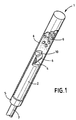
- Figure 1 is a perspective view, with partial cutaway, of an igniter formed from an initiator according to the invention shown for reasons of clarity of the figure without protective mask.
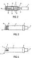
- FIGS. 2 , 3 and 4 illustrate the successive stages of constitution of an initiator according to the invention from its circuit support.
- FIG. 5 illustrates a printed circuit on which the electromagnetic protection is provided by capacitors.
- FIG. 6 illustrates a printed circuit on which the electromagnetic protection is provided by a traditional filter coil.
- FIG. 7 illustrates a printed circuit on which the electromagnetic protection is provided by a coil printed in a multilayer circuit.
- FIG. 8 is a sectional view of an initiator comprising two separate ignition heads, the heat-sensitive charges of which are partially maintained by overmolding.
- FIG. 1 shows an igniter 1 consisting of an initiator 2 connected to a cable electric 3.
- the initiator 2 is contained mainly in a cylindrical overmold 4 having on the cable side 3 a base 5 of diameter slightly higher.
- the initiator 2 has, at its end opposite to the base 5, an ignition head which will be described in details a little further but which can be observed that it has a thermosensitive filler 6 based on lead trinitroresorcinate which is protected by a mask 7 made of transparent plastic not shown in Figure 1.
- a metal cap fragmentable 8 of cylindrical shape encloses the overmolding 4 by resting on the base 5. This cap is closed at its end opposite the base 5 and contains a pyrotechnic charge 9 generator gas.
- the constitution of initiator 2 is now described in detail with particular reference in Figures 2 to 5.
- the initiator 2 is formed from of a printed circuit support 10 which has the form of a thin parallelepiped card with two sides opposite planes.
- This support 10 is formed from an epoxy resin loaded with glass fibers.
- On one two conductive strips 11 are printed on its faces and 12 which are each welded at one of their ends to the conductive wires 13 and 14 constituting the cable electric 3.
- a resistive heating element 15 connects between them the free ends of the strips conductive 11 and 12.
- This resistive heating element 15 can be a resistive wire but will be advantageously consisting of a defined resistive heating strip by a printed sub-circuit 16 as described in the patent US-A-5, 544 585 or in its correspondent FR-A-2 704,944, the description of which is included, by reference, to this description.
- the resistive heating element 15 may also be made up of a diode or a semiconductor bridge as described for example in the request for Patent FR-A-2,720,493.
- Two capacitors 17 and 18 are removed and connected to the circuit formed by the strips conductive 11 and 12 as well as by the resistive element 15. These capacitors are the means of electromagnetic protection of the circuit by preventing discharge of stray currents through the element 15.
- electromagnetic protection means could also consist of a coil filter 61 deposited and connected to a printed circuit on a support 60 and constituted by two strips conductive 62 and 63 interconnected by an element resistive 64 as shown in Figure 6.
- a variant for making such electromagnetic protection is shown in Figure 7.
- On a support 70 is printed a circuit consisting of two strips conductive 72 and 73 interconnected by an element resistive 74.
- the conductive strip 72 forms around the support 70 a coil 71 constituting with the strip 73 a multilayer circuit.
- the part of the face of the support 10 on which are printed strips 11 and 12 and on which rest capacitor 17 and 18 is covered by a layer of insulating varnish 19.
- This layer 19 does not cover the end of the support 10 which carries the resistive element 15 and which will constitute the ignition head of initiator.
- the support 10 is partially surrounded by a cylindrical overmolding 4 in adhesive resin based on hot-melt polyamide.
- thermosensitive filler 6 for example based on lead trinitroresorcinate.
- Load 6 is protected by a mask 7 made of transparent plastic. Initiator 2 is thus completed and can be used to constitute the igniter 1 described above.
- FIG. 8 shows an initiator 82 which constitutes an alternative embodiment of the initiator 2 which has just been described.
- Initiator 82 is built around a card-shaped circuit support 80 thin parallelepiped.
- the essential difference between this initiator 82 and the initiator 2 described more high resides in the fact that each of the two faces of the support 80 carries a complete printed circuit 87 or 89 connected to the same 83 power supply cable electric.
- the support 80 is partially coated with a cylindrical overmolding 84 which has a base widened 85 and which partially maintains the loads thermosensitive 86 and 88 constituting the heads ignition. In this realization, the initiator does not no protective mask required.
- thermosensitive In case of arrival current through cable 83 both loads thermosensitive are simultaneously ignited and initiator 82 thus presents a very large efficiency in normal operation and very high safety both with regard to stray currents thanks to its electromagnetic protections 91.93 or 92.94 integrated only vis-à-vis possible misfires thanks to the doubling of the heads.
Description
Claims (10)
- Initiateur électropyrotechnique (2) connecté à un câble électrique (3) constitué par deux fils conducteurs (13,14) comprenant notamment :et dans lequel le dit circuit électrique et les dits moyens de protection électromagnétique sont intégrés dans un circuit de bandes conductrices (11,12) qui sont soudées aux dits fils conducteurs (13,14) et qui sont formées sur un support de circuit imprimé (10,60,70,80) qui a la forme d'une carte parallélépipédique mince présentant deux faces planes opposées, et autour duquel est constitué le dit initiateur, caractérisé en ce que le dit élément résistif chauffant est constitué par une bande résistive (16) et en ce que le dit circuit est formé sur l'une des dites faces.i) une charge thermosensible (6) déposée sur un élément résistif chauffant (15),ii) un circuit électrique reliant le dit élément résistif (15) aux dits fils conducteurs (13,14),iii) des moyens de protection électromagnétique du dit circuit,
- Initiateur selon la revendication 1 caractérisé en ce que les dits moyens de protection électromagnétique sont constitués par au moins une bobine filtrante (61) déposée sur le dit support de circuit (60).
- Initiateur selon la revendication 1 caractérisé en ce que les dits moyens de protection électromagnétique sont constitués par au moins une bobine filtrante (71) imprimée sur le dit support de circuit (70).
- Initiateur selon la revendication 1 caractérisé en ce que les dits moyens de protection électromagnétique sont constitués par au moins un condensateur (17,18) déposé sur le dit support de circuit (10).
- Initiateur selon la revendication 1 caractérisé en ce que le dit circuit électrique et les dits moyens de protection électromagnétique sont recouverts par une couche de vernis isolant (19).
- Initiateur selon l'une quelconque des revendications 1 ou 5 caractérisé en ce que le dit support de circuit (10) est partiellement enrobé par un surmoulage isolant (4).
- Initiateur selon la revendication 6 caractérisé en ce que la dite charge thermosensible (6) est protégée par un masque fragmentable (7).
- Initiateur selon la revendication 1 caractérisé en ce que sur chacune des deux faces plane du support de circuit (80) est imprimé un circuit distinct (87,89) de bandes conductrices incluant chacun un élément résistif chauffant recouvert par une charge thermosensible (86,88) et des moyens de protection électromagnétique (91,93 ; 92,94).
- Allumeur (1) électro-pyrotechnique caractérisé en ce qu'un initiateur selon l'une quelconque des revendications 1 à 8 est entouré par un capuchon fragmentable (8) contenant une poudre d'allumage (9).
- Utilisation d'un initiateur électro-pyrotechnique selon l'une quelconque des revendications 1 à 8 pour provoquer l'allumage d'un générateur pyrotechnique de gaz destiné à gonfler un coussin de protection pour occupant d'un véhicule automobile.
Applications Claiming Priority (2)
| Application Number | Priority Date | Filing Date | Title |
|---|---|---|---|
| FR9702715 | 1997-03-07 | ||
| FR9702715A FR2760525B1 (fr) | 1997-03-07 | 1997-03-07 | Initiateur electro-pyrotechnique constitue autour d'un circuit imprime complet |
Publications (2)
| Publication Number | Publication Date |
|---|---|
| EP0863379A1 EP0863379A1 (fr) | 1998-09-09 |
| EP0863379B1 true EP0863379B1 (fr) | 2001-12-19 |
Family
ID=9504513
Family Applications (1)
| Application Number | Title | Priority Date | Filing Date |
|---|---|---|---|
| EP98400495A Expired - Lifetime EP0863379B1 (fr) | 1997-03-07 | 1998-03-03 | Initiateur électro-pyrotechnique constitué autour d'un circuit imprimé complet |
Country Status (7)
| Country | Link |
|---|---|
| US (2) | US6389972B2 (fr) |
| EP (1) | EP0863379B1 (fr) |
| JP (1) | JP2914952B2 (fr) |
| KR (1) | KR100295356B1 (fr) |
| DE (1) | DE69802979T2 (fr) |
| ES (1) | ES2169486T3 (fr) |
| FR (1) | FR2760525B1 (fr) |
Families Citing this family (16)
| Publication number | Priority date | Publication date | Assignee | Title |
|---|---|---|---|---|
| US6662727B2 (en) * | 1996-03-14 | 2003-12-16 | Dynamit Nobel Gmbh | Gas generator, in particular for belt tighteners |
| EP0993589B1 (fr) * | 1997-07-09 | 2002-10-02 | Siemens Aktiengesellschaft | Systeme d'allumage |
| AT2781U1 (de) * | 1998-03-09 | 1999-04-26 | Hirtenberger Praezisionstechni | Elektrisch auslösbarer zünder zum anschiessen einer treibladung |
| FR2790077B1 (fr) | 1999-02-18 | 2001-12-28 | Livbag Snc | Allumeur electro-pyrotechnique a electronique integree |
| US6341562B1 (en) * | 2000-02-22 | 2002-01-29 | Autoliv Asp, Inc. | Initiator assembly with activation circuitry |
| FR2832499B1 (fr) * | 2001-11-19 | 2004-02-06 | Delta Caps Internat Dci | Module de commande electronique pour detonateur |
| CA2483163C (fr) * | 2002-04-24 | 2011-11-01 | Samsung Electronics Co., Ltd. | Support optique de stockage d'informations et procede d'enregistrement sur ce dernier |
| DE10240053A1 (de) * | 2002-08-30 | 2004-03-11 | Robert Bosch Gmbh | Brückenzünder-Zündelement |
| US6739264B1 (en) * | 2002-11-04 | 2004-05-25 | Key Safety Systems, Inc. | Low cost ignition device for gas generators |
| JP3803636B2 (ja) * | 2002-12-26 | 2006-08-02 | 本田技研工業株式会社 | バス接続用点火装置 |
| FR2857738B1 (fr) * | 2003-07-17 | 2006-01-20 | Giat Ind Sa | Composant pyrotechnique et procede de fabrication et de montage d'un tel composant |
| US7343859B2 (en) * | 2003-11-10 | 2008-03-18 | Honda Motor Co., Ltd. | Squib |
| CN2859269Y (zh) * | 2005-11-22 | 2007-01-17 | 长沙凯维科技有限公司 | 一种烟花电点火头 |
| DE102006009554A1 (de) * | 2006-02-28 | 2007-08-30 | Comet Gmbh Pyrotechnik-Apparatebau | Vorrichtung zur Erzeugung pyrotechnischer Effekte |
| JP5364354B2 (ja) * | 2008-12-08 | 2013-12-11 | 日本工機株式会社 | 携行型拘束網展開装置 |
| DE102009051768B4 (de) | 2009-10-30 | 2013-12-12 | Stiftung Alfred-Wegener-Institut Für Polar- Und Meeresforschung | Elektrochemisches Antifoulingsystem für seewasserbenetzte Bauwerke |
Family Cites Families (36)
| Publication number | Priority date | Publication date | Assignee | Title |
|---|---|---|---|---|
| BE488616A (fr) * | 1948-04-30 | |||
| US3802018A (en) | 1968-09-27 | 1974-04-09 | Copperloy Corp | Suspension for mobile ramp structure |
| US3804018A (en) * | 1970-06-04 | 1974-04-16 | Ici America Inc | Initiator and blasting cap |
| US4788913A (en) * | 1971-06-02 | 1988-12-06 | The United States Of America As Represented By The United States Department Of Energy | Flying-plate detonator using a high-density high explosive |
| US3735705A (en) * | 1971-07-15 | 1973-05-29 | Amp Inc | Filtered electro-explosive device |
| US4145970A (en) * | 1976-03-30 | 1979-03-27 | Tri Electronics Ab | Electric detonator cap |
| US4040356A (en) * | 1976-07-06 | 1977-08-09 | The United States Of America As Represented By The Secretary Of The Army | Converging wave detonator |
| DE2816726A1 (de) * | 1978-04-18 | 1979-10-31 | Daimler Benz Ag | Insassen-rueckhaltesystem fuer fahrzeuge |
| FR2438820A1 (fr) * | 1978-10-13 | 1980-05-09 | France Etat | Dispositif electrique d'allumage d'une substance pyrotechnique |
| US4380958A (en) * | 1980-12-17 | 1983-04-26 | The United States Of America As Represented By The Secretary Of The Army | Electrostatic safe electric match |
| GB2123122A (en) * | 1982-01-08 | 1984-01-25 | Hunting Eng Ltd | Explosive devices |
| DE3567268D1 (en) * | 1984-01-31 | 1989-02-09 | Dynamit Nobel Ag | Electric ignitor |
| DE8432097U1 (de) * | 1984-11-02 | 1986-07-17 | Dynamit Nobel Ag, 5210 Troisdorf | Elektronischer Sprengzeitzünder |
| US4712477A (en) * | 1985-06-10 | 1987-12-15 | Asahi Kasei Kogyo Kabushiki Kaisha | Electronic delay detonator |
| GB2190730B (en) * | 1986-05-22 | 1990-10-24 | Detonix Close Corp | Detonator firing element |
| DE3637988A1 (de) * | 1986-11-07 | 1988-05-11 | Diehl Gmbh & Co | Anzuendbauteil |
| DE3643301A1 (de) * | 1986-12-18 | 1988-06-30 | Diehl Gmbh & Co | Elektrisches anzuendstueck |
| SE456939B (sv) | 1987-02-16 | 1988-11-14 | Nitro Nobel Ab | Spraengkapsel |
| US4722551A (en) | 1987-03-19 | 1988-02-02 | Morton Thiokol, Inc. | Initiator and method for the incorporation thereof in an inflator |
| US4852493A (en) * | 1988-02-12 | 1989-08-01 | The United States Of America As Represented By The United States Department Of Energy | Ferrite core coupled slapper detonator apparatus and method |
| US4862803A (en) * | 1988-10-24 | 1989-09-05 | Honeywell Inc. | Integrated silicon secondary explosive detonator |
| US5355800A (en) * | 1990-02-13 | 1994-10-18 | Dow Robert L | Combined EED igniter means and means for protecting the EED from inadvertent extraneous electricity induced firing |
| US5099762A (en) * | 1990-12-05 | 1992-03-31 | Special Devices, Incorporated | Electrostatic discharge immune electric initiator |
| US5080016A (en) * | 1991-03-20 | 1992-01-14 | The United States Of America As Represented By The Department Of Energy | Hydrogen loaded metal for bridge-foils for enhanced electric gun/slapper detonator operation |
| US5200574A (en) | 1991-04-05 | 1993-04-06 | Morton International, Inc. | Universal squib connector |
| US5309841A (en) * | 1991-10-08 | 1994-05-10 | Scb Technologies, Inc. | Zener diode for protection of integrated circuit explosive bridge |
| CA2103510A1 (fr) | 1992-09-11 | 1994-03-12 | Bradley D. Harris | Pont a circuit imprime pour dispositif de gonflage de coussin |
| FR2704944B1 (fr) | 1993-05-05 | 1995-08-04 | Ncs Pyrotechnie Technologies | Initiateur électro-pyrotechnique. |
| DE4435319A1 (de) * | 1994-10-01 | 1996-04-04 | Temic Bayern Chem Airbag Gmbh | Anzündeinheit für einen Gasgenerator eines passiven Rückhaltesystems |
| US5847309A (en) * | 1995-08-24 | 1998-12-08 | Auburn University | Radio frequency and electrostatic discharge insensitive electro-explosive devices having non-linear resistances |
| ES2164931T3 (es) * | 1995-12-06 | 2002-03-01 | Orica Explosives Tech Pty Ltd | Dispositivo electronico para iniciar explosivos. |
| US6662727B2 (en) * | 1996-03-14 | 2003-12-16 | Dynamit Nobel Gmbh | Gas generator, in particular for belt tighteners |
| DE19609908A1 (de) * | 1996-03-14 | 1997-09-18 | Dynamit Nobel Ag | Gasgenerator, insbesondere für Gurtstraffer |
| US6079332A (en) * | 1996-11-01 | 2000-06-27 | The Ensign-Bickford Company | Shock-resistant electronic circuit assembly |
| US5889228A (en) * | 1997-04-09 | 1999-03-30 | The Ensign-Bickford Company | Detonator with loosely packed ignition charge and method of assembly |
| US5821446A (en) * | 1997-05-27 | 1998-10-13 | Trw Inc. | Inflator for an inflatable vehicle occupant protection device |
-
1997
- 1997-03-07 FR FR9702715A patent/FR2760525B1/fr not_active Expired - Fee Related
-
1998
- 1998-03-03 EP EP98400495A patent/EP0863379B1/fr not_active Expired - Lifetime
- 1998-03-03 DE DE69802979T patent/DE69802979T2/de not_active Expired - Fee Related
- 1998-03-03 ES ES98400495T patent/ES2169486T3/es not_active Expired - Lifetime
- 1998-03-06 KR KR1019980007412A patent/KR100295356B1/ko not_active IP Right Cessation
- 1998-03-06 JP JP10055146A patent/JP2914952B2/ja not_active Expired - Fee Related
- 1998-03-09 US US09/038,931 patent/US6389972B2/en not_active Expired - Fee Related
-
2002
- 2002-01-07 US US10/036,534 patent/US6539875B2/en not_active Expired - Fee Related
Also Published As
| Publication number | Publication date |
|---|---|
| JP2914952B2 (ja) | 1999-07-05 |
| DE69802979T2 (de) | 2002-06-27 |
| FR2760525A1 (fr) | 1998-09-11 |
| FR2760525B1 (fr) | 1999-04-16 |
| JPH10253299A (ja) | 1998-09-25 |
| KR19980079959A (ko) | 1998-11-25 |
| EP0863379A1 (fr) | 1998-09-09 |
| US6539875B2 (en) | 2003-04-01 |
| KR100295356B1 (ko) | 2001-09-17 |
| US20020078848A1 (en) | 2002-06-27 |
| US6389972B2 (en) | 2002-05-21 |
| DE69802979D1 (de) | 2002-01-31 |
| ES2169486T3 (es) | 2002-07-01 |
| US20010022146A1 (en) | 2001-09-20 |
Similar Documents
| Publication | Publication Date | Title |
|---|---|---|
| EP0863379B1 (fr) | Initiateur électro-pyrotechnique constitué autour d'un circuit imprimé complet | |
| EP1030158B1 (fr) | Allumeur électro-pyrotechnique à électronique integrée | |
| EP1180659B1 (fr) | Allumeur électro-pyrotechnique à deux têtes d'allumage et utilisation en sécurité automobile | |
| EP1030159B1 (fr) | Allumeur électropyrotechnique à sécurité d'allumage renforcé | |
| EP1098162B1 (fr) | Initiateur pyrotechnique à filament photogravé protégé contre les décharges électrostatiques | |
| EP0631104B1 (fr) | Initiateur électro-pyrotechnique | |
| FR2809806A1 (fr) | Initiateur electro-pyrotechnique a pont en couche mince et a tres basse energie de fonctionnement | |
| EP0803700B1 (fr) | Initiateur à prise bifilaire auto-bloquante pour générateurs pyrotechniques de gaz | |
| EP1092938B1 (fr) | Allumeur électrique du type à pont | |
| FR2772909A1 (fr) | Initiateur electro-pyrotechnique a trois connexions electriques | |
| US6591754B1 (en) | Pyrotechnical ignition system with integrated ignition circuit | |
| EP1672308B1 (fr) | Disposition d'initiation pour charge explosive ou composition pyrotechnique | |
| FR2796715A1 (fr) | Initiateur pyrotechnique et procede de montage d'un tel initiateur | |
| FR2875594A1 (fr) | Initiateur electro-pyrotechnique | |
| JP6721483B2 (ja) | 点火器 | |
| WO1999060518A1 (fr) | Support pour un circuit electronique, comprenant des moyens anti-arrachement | |
| FR2660749A1 (fr) | Systeme de declenchement sequentiel controle et automatique d'une pluralite de charges utiles pyrotechniques. | |
| WO1990015439A1 (fr) | Circuit electronique en boitier avec puce sur zone quadrillee de plots conducteurs | |
| FR2726124A1 (fr) | Boitier pour dispositif a semiconducteur | |
| FR2857738A1 (fr) | Composant pyrotechnique et procede de fabrication et de montage d'un tel composant | |
| CN1176690A (zh) | 电雷管和引线连接器组合件 | |
| JPH0731519U (ja) | 乗員保護システムの作動装置 |
Legal Events
| Date | Code | Title | Description |
|---|---|---|---|
| PUAI | Public reference made under article 153(3) epc to a published international application that has entered the european phase |
Free format text: ORIGINAL CODE: 0009012 |
|
| AK | Designated contracting states |
Kind code of ref document: A1 Designated state(s): DE ES FR GB IT SE |
|
| 17P | Request for examination filed |
Effective date: 19990309 |
|
| AKX | Designation fees paid |
Free format text: DE ES FR GB IT SE |
|
| RBV | Designated contracting states (corrected) |
Designated state(s): DE ES FR GB IT SE |
|
| 17Q | First examination report despatched |
Effective date: 20000412 |
|
| GRAG | Despatch of communication of intention to grant |
Free format text: ORIGINAL CODE: EPIDOS AGRA |
|
| GRAG | Despatch of communication of intention to grant |
Free format text: ORIGINAL CODE: EPIDOS AGRA |
|
| GRAH | Despatch of communication of intention to grant a patent |
Free format text: ORIGINAL CODE: EPIDOS IGRA |
|
| GRAH | Despatch of communication of intention to grant a patent |
Free format text: ORIGINAL CODE: EPIDOS IGRA |
|
| GRAA | (expected) grant |
Free format text: ORIGINAL CODE: 0009210 |
|
| AK | Designated contracting states |
Kind code of ref document: B1 Designated state(s): DE ES FR GB IT SE |
|
| REG | Reference to a national code |
Ref country code: GB Ref legal event code: IF02 |
|
| REF | Corresponds to: |
Ref document number: 69802979 Country of ref document: DE Date of ref document: 20020131 |
|
| GBT | Gb: translation of ep patent filed (gb section 77(6)(a)/1977) |
Effective date: 20020319 |
|
| REG | Reference to a national code |
Ref country code: ES Ref legal event code: FG2A Ref document number: 2169486 Country of ref document: ES Kind code of ref document: T3 |
|
| PLBE | No opposition filed within time limit |
Free format text: ORIGINAL CODE: 0009261 |
|
| STAA | Information on the status of an ep patent application or granted ep patent |
Free format text: STATUS: NO OPPOSITION FILED WITHIN TIME LIMIT |
|
| 26N | No opposition filed | ||
| REG | Reference to a national code |
Ref country code: FR Ref legal event code: TP |
|
| PGFP | Annual fee paid to national office [announced via postgrant information from national office to epo] |
Ref country code: ES Payment date: 20090318 Year of fee payment: 12 |
|
| PGFP | Annual fee paid to national office [announced via postgrant information from national office to epo] |
Ref country code: GB Payment date: 20090121 Year of fee payment: 12 |
|
| PGFP | Annual fee paid to national office [announced via postgrant information from national office to epo] |
Ref country code: SE Payment date: 20090123 Year of fee payment: 12 Ref country code: DE Payment date: 20090127 Year of fee payment: 12 |
|
| PGFP | Annual fee paid to national office [announced via postgrant information from national office to epo] |
Ref country code: FR Payment date: 20090121 Year of fee payment: 12 |
|
| EUG | Se: european patent has lapsed | ||
| GBPC | Gb: european patent ceased through non-payment of renewal fee |
Effective date: 20100303 |
|
| REG | Reference to a national code |
Ref country code: FR Ref legal event code: ST Effective date: 20101130 |
|
| PG25 | Lapsed in a contracting state [announced via postgrant information from national office to epo] |
Ref country code: FR Free format text: LAPSE BECAUSE OF NON-PAYMENT OF DUE FEES Effective date: 20100331 |
|
| PG25 | Lapsed in a contracting state [announced via postgrant information from national office to epo] |
Ref country code: DE Free format text: LAPSE BECAUSE OF NON-PAYMENT OF DUE FEES Effective date: 20101001 |
|
| PG25 | Lapsed in a contracting state [announced via postgrant information from national office to epo] |
Ref country code: GB Free format text: LAPSE BECAUSE OF NON-PAYMENT OF DUE FEES Effective date: 20100303 Ref country code: IT Free format text: LAPSE BECAUSE OF NON-PAYMENT OF DUE FEES Effective date: 20090303 |
|
| REG | Reference to a national code |
Ref country code: ES Ref legal event code: FD2A Effective date: 20110419 |
|
| PG25 | Lapsed in a contracting state [announced via postgrant information from national office to epo] |
Ref country code: ES Free format text: LAPSE BECAUSE OF NON-PAYMENT OF DUE FEES Effective date: 20110404 |
|
| PGFP | Annual fee paid to national office [announced via postgrant information from national office to epo] |
Ref country code: IT Payment date: 20090317 Year of fee payment: 12 |
|
| PGRI | Patent reinstated in contracting state [announced from national office to epo] |
Ref country code: IT Effective date: 20110616 |
|
| PG25 | Lapsed in a contracting state [announced via postgrant information from national office to epo] |
Ref country code: ES Free format text: LAPSE BECAUSE OF NON-PAYMENT OF DUE FEES Effective date: 20100304 |
|
| PG25 | Lapsed in a contracting state [announced via postgrant information from national office to epo] |
Ref country code: SE Free format text: LAPSE BECAUSE OF NON-PAYMENT OF DUE FEES Effective date: 20100304 |
|
| PGRI | Patent reinstated in contracting state [announced from national office to epo] |
Ref country code: IT Effective date: 20110616 |