EP1098162B1 - Initiateur pyrotechnique à filament photogravé protégé contre les décharges électrostatiques - Google Patents
Initiateur pyrotechnique à filament photogravé protégé contre les décharges électrostatiques Download PDFInfo
- Publication number
- EP1098162B1 EP1098162B1 EP00402813A EP00402813A EP1098162B1 EP 1098162 B1 EP1098162 B1 EP 1098162B1 EP 00402813 A EP00402813 A EP 00402813A EP 00402813 A EP00402813 A EP 00402813A EP 1098162 B1 EP1098162 B1 EP 1098162B1
- Authority
- EP
- European Patent Office
- Prior art keywords
- electrodes
- foil
- initiator
- shape
- layer
- Prior art date
- Legal status (The legal status is an assumption and is not a legal conclusion. Google has not performed a legal analysis and makes no representation as to the accuracy of the status listed.)
- Expired - Lifetime
Links
Images

Classifications
-
- B—PERFORMING OPERATIONS; TRANSPORTING
- B60—VEHICLES IN GENERAL
- B60R—VEHICLES, VEHICLE FITTINGS, OR VEHICLE PARTS, NOT OTHERWISE PROVIDED FOR
- B60R21/00—Arrangements or fittings on vehicles for protecting or preventing injuries to occupants or pedestrians in case of accidents or other traffic risks
- B60R21/02—Occupant safety arrangements or fittings, e.g. crash pads
- B60R21/16—Inflatable occupant restraints or confinements designed to inflate upon impact or impending impact, e.g. air bags
- B60R21/26—Inflatable occupant restraints or confinements designed to inflate upon impact or impending impact, e.g. air bags characterised by the inflation fluid source or means to control inflation fluid flow
- B60R21/264—Inflatable occupant restraints or confinements designed to inflate upon impact or impending impact, e.g. air bags characterised by the inflation fluid source or means to control inflation fluid flow using instantaneous generation of gas, e.g. pyrotechnic
-
- F—MECHANICAL ENGINEERING; LIGHTING; HEATING; WEAPONS; BLASTING
- F42—AMMUNITION; BLASTING
- F42B—EXPLOSIVE CHARGES, e.g. FOR BLASTING, FIREWORKS, AMMUNITION
- F42B3/00—Blasting cartridges, i.e. case and explosive
- F42B3/10—Initiators therefor
- F42B3/18—Safety initiators resistant to premature firing by static electricity or stray currents
-
- B—PERFORMING OPERATIONS; TRANSPORTING
- B60—VEHICLES IN GENERAL
- B60R—VEHICLES, VEHICLE FITTINGS, OR VEHICLE PARTS, NOT OTHERWISE PROVIDED FOR
- B60R21/00—Arrangements or fittings on vehicles for protecting or preventing injuries to occupants or pedestrians in case of accidents or other traffic risks
- B60R21/01—Electrical circuits for triggering passive safety arrangements, e.g. airbags, safety belt tighteners, in case of vehicle accidents or impending vehicle accidents
-
- B—PERFORMING OPERATIONS; TRANSPORTING
- B60—VEHICLES IN GENERAL
- B60R—VEHICLES, VEHICLE FITTINGS, OR VEHICLE PARTS, NOT OTHERWISE PROVIDED FOR
- B60R21/00—Arrangements or fittings on vehicles for protecting or preventing injuries to occupants or pedestrians in case of accidents or other traffic risks
- B60R21/02—Occupant safety arrangements or fittings, e.g. crash pads
- B60R21/16—Inflatable occupant restraints or confinements designed to inflate upon impact or impending impact, e.g. air bags
- B60R21/26—Inflatable occupant restraints or confinements designed to inflate upon impact or impending impact, e.g. air bags characterised by the inflation fluid source or means to control inflation fluid flow
-
- F—MECHANICAL ENGINEERING; LIGHTING; HEATING; WEAPONS; BLASTING
- F42—AMMUNITION; BLASTING
- F42B—EXPLOSIVE CHARGES, e.g. FOR BLASTING, FIREWORKS, AMMUNITION
- F42B3/00—Blasting cartridges, i.e. case and explosive
- F42B3/10—Initiators therefor
- F42B3/12—Bridge initiators
- F42B3/124—Bridge initiators characterised by the configuration or material of the bridge
-
- F—MECHANICAL ENGINEERING; LIGHTING; HEATING; WEAPONS; BLASTING
- F42—AMMUNITION; BLASTING
- F42B—EXPLOSIVE CHARGES, e.g. FOR BLASTING, FIREWORKS, AMMUNITION
- F42B3/00—Blasting cartridges, i.e. case and explosive
- F42B3/10—Initiators therefor
- F42B3/12—Bridge initiators
- F42B3/13—Bridge initiators with semiconductive bridge
Definitions
- the present invention relates to the field of electro-pyrotechnic initiators intended to fire the pyrotechnic charges of the generators of gas to activate protective devices for occupants of motor vehicles. More precisely the invention relates to an initiator whose initiation head has a leaf circuit thick-layered metal and which is well protected against electrostatic discharges.
- electro-pyrotechnic initiators intended for automotive safety are consisting of an insulating body extended by a cap fragmentable metal and crossed by two electrodes.
- the electrodes are interconnected by a filament resistive heating surrounded by an explosive composition starting material, for example a composition based on lead triresorcinate.
- an explosive composition starting material for example a composition based on lead triresorcinate.
- Such lighters that are example described in US Patents 4,517,895
- US Pat. No. 4,959,011 has the drawback to be sensitive to the vibrations of the motor vehicle at level of the resistive filament welds on the electrodes. These welds when requested repetitively by the vibrations of the vehicle may break and render the igniter ineffective.
- initiators in which the electrodes are in contact with two conductive metal sheets distinct stretches on the surface of the insulating body that is inside the metal cap. These two tablecloths are interconnected by a flat band resistive of small width deposited on the surface of the insulating body. Conductive layers and tape resistive are covered by an explosive composition boot.
- initiators are divided into two great families. On the one hand initiators whose conductive sheets are constituted by printed circuits, such as those described, for example in European Patent EP 0 802 092; and on the other hand the initiators whose conductive sheets and the resistive strip consist of a stack of photo-etched metal sheets such as those described, for example, in US Pat. No. 5,544,585.
- the initiators corresponding to this latter family are often so-called “thick-film initiators", the thickness of each metal foil being generally between 2x10 -6 m and 7x10 -6 m, or between 2 and 7 micrometers.
- Initiators whose conductive layers are printed circuits make it possible to easily soldering in surface mounting of components such as varistors or capacitors that ensure the initiator a very good electrostatic protection.
- the object of the present invention is precisely to propose initiators with thick-layered leaves which are well protected against landfills electrostatic while not requiring any soldering of electronic components being assembled.
- the smallest distance between the edge of the insulating support and the outer contour of the thick-film circuit is at least 35 ⁇ 10 -5 m.
- said middle portion is of constant width.
- the initiators according to the invention are very simple and robust, they have no components additional fixed by welding and are easy to manufacture when the thick-filmed circuit is photogravure as described, for example, in US Patent 5, 544, 585. It has been observed that these initiators exhibit remarkable resistance to electrostatic discharges, especially when the form of the thick-layered leaf circuit is such that the plane connecting the two electrodes crosses, at the level of the support, an alternation of zones conductive and insulating areas as will be described in more detail later in the description.
- the first sheet will be advantageously constituted by a resistive alloy based on nickel and chromium while the second layer will be advantageously constituted by a copper foil.
- the second sheet can advantageously be covered by a third layer that will be a deposit Tin-based tinning of shape and thickness similar to the parts of the second layer that it overwrite.
- the initiators according to the invention can thus be easily mass-produced at modest cost and find their favorite application in pyrotechnic gas generators intended to activate protective devices for the occupants of a motor vehicle.
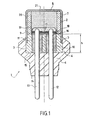
- FIG. 1 An electro-pyrotechnic initiator 1 according to the invention is represented in FIG. 1.
- This initiator 1 is constituted by a cylindrical container 2 fragmentable open at one of its ends.
- a body solid cylindrical 3 closes the open end of the container 2.
- the side wall 4 of the body 3 has a external shoulder 5 on which the end supports open container 2.
- Container 2 and body 3 are contained in an overmoulding 6 which keeps them in solidarity with each other.
- the container 2 thus has the shape of a cylindrical cap having a wall side 7 and a closed closed end 8.
- the container 2 is advantageously constituted by a metal light end like aluminum and its flat face is advantageously weakened to be able to open easily under the effect of an increase in pressure inside the container.
- the overmoulding 6 is produced preferentially in a resin thermoplastic such as, for example, terephthalate polyethylene.
- the body 3 must be able to act as a wall sealed to detonation and flue gases resulting from this detonation.
- This body 3 is preferentially made in a dense metal like steel.
- the body 3 has a planar upper face 9 and a lower face 15 also flat and it encloses, throughout its height h, two glass hollow tubes 10 and 11. Each of these tubes contains an electrode 12, 13 in pin shape.
- Each electrode has an end that protrudes the flat upper face 9 of the body 3 and one end which exceeds the underside 14 of the overmolding 6.
- an insulating support 16 constituted by a plate made from a glass / resin mixture, as, for example, a polyepoxy resin. Electrodes 12 and 13 pass through and exceed the insulating support 16.
- the insulating support 16 carries an electrical circuit 18 with thick-layered leaves containing an element resistive heating plate 17. This circuit that is going to be described in detail a little further is crossed by the electrodes 12 and 13 and electrically connected to these latest.
- the circuit 18 comprising the resistive element 17 is covered by a pyrotechnic composition initiator 19, for example, based on trinitroresorcinate lead.
- Container 2 also contains a tube metal 20 reinforcing the side wall 7. A inside the tube 20 is placed an ignition powder 21 constituted, for example, by a powder-based nitrocellulose or a mixture of boron and nitrate of potassium.
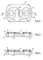
- Circuit 18 is now described with reference more particularly to Figures 2,3, and 4.
- the circuit 18 is carried by the insulating support 16 which has the shape of a plate comprising two cylindrical channels 22 and 23 for passing the electrodes 12 and 13.
- the circuit 18 is basically constituted by a first sheet 24 of resistive metal alloy, for example an alloy based on nickel and chromium.
- This sheet whose thickness is between 2 and 7 microns, that is to say between 2x10 -6 m and 7x10 -6 m, does not cover the channels 22 and 23 and has a shape that presents, between the channels 22 and 23 in which will pass the electrodes 12 and 13, a middle portion of constant width which will constitute the flat resistive element 17.
- the outer contour 25 of this sheet 24 is constituted by curved lines whose radii of curvature are greater than 0.7mm, that is to say 7x10 -4 m.
- the smallest distance between the edges 26 of the insulating support 16 and the outer contour 25 of the sheet 24 must be at least equal to 0.35 mm, that is to say 35x10 -5 m.
- the first sheet 24 is covered, with the exception of the middle part constituting the flat resistive element 17, by a second conductive metal layer 27, for example made of copper.
- This second layer 27 serves to form two conductive metal sheets 28 and 29 which will be traversed by the electrodes 12 and 13 and which will be electrically connected thereto. These sheets have a shape identical to the shape of the parts of the sheet 24 that they cover.
- the thickness of the second layer 27 is similar to that of the sheet 24.
- the second layer 27 can advantageously be covered by a third layer 30 which will be constituted by a deposit tinning of similar shape and thickness to those of the second layer 27 and that will leave so free the flat resistive element 17 belonging to the first sheet 24.
- the thicknesses of the layers 24, 27 and 30 are not proportional to the thickness of the insulating support 16.
- An initiator according to the invention is moreover particularly simple and economical to manufacture in series.
- the initiators to thick layered leaves being otherwise particularly resistant to vibrations, these initiators find a preferred application in the field of protection, by pyrotechnics, occupants of a motor vehicle.
- This device consists of two clamps connected conductors 31 and 32, via a switch 33, a resistor 34 and a capacitor 35 connected in series.
- Resistance 34 has a R value and the capacitor 35 has a capacitance C and is charged under a voltage U.
- the clamp 31 is fixed on the electrode 37 of the initiator 39 that one wants to test, while the gripper 32 is fixed, optionally, on the electrode 36 or the cap 38 of the initiator 39. It is thus possible to measure, by closing switch 33, the resistance of the initiator to electrical discharges in the configurations usually tested and known by their names Anglo-Saxon "pin to pin” or "pin to case".
Description
- le circuit à feuilles en couches épaisses comprend une première couche constituée par une première feuille en alliage métallique résistif, d'épaisseur comprise entre 2x10⁻⁶m et 7x10⁻⁶m, collée sur le dit support et traversée par les dites électrodes, la dite première feuille ayant une forme qui présente, entre les électrodes, une partie médiane constituant l'élément résistif plat et dont le contour externe, à l'exception de la dite partie médiane, est constitué par des lignes courbes dont les rayons de courbure sont supérieurs à 7x10⁻⁴m, la dite première feuille étant recouverte, à l'exception de la dite partie médiane, par une seconde couche métallique conductrice servant à constituer les nappes métalliques qui sont traversées par les dites électrodes et qui sont de forme et d'épaisseur analogues à celles des parties de la première feuille qu'elles recouvrent.
| LOT | R | C |
| A | 5 000 ohms | 500 picofarads |
| B | 330 ohms | 150 picofarads |
Claims (8)
- Initiateur électro-pyrotechnique (1) protégé contre les décharges électrostatiques comportant, à l'intérieur d'un conteneur fragmentable (2) fermé et supporté par un surmoulage (6), une tête d'initiation constituée par une paroi étanche formée par un corps massif (3) de hauteur h qui possède une face supérieure plane (9) et qui enserre, sur toute sa hauteur h, une structure vitreuse (10, 11) traversée par deux électrodes (12, 13) en forme de broches, les dites électrodes ayant chacune une extrémité qui dépasse la dite face supérieure plane, ce dépassement permettant de les connecter électriquement à un circuit électrique (18) à feuilles en couches épaisses qui est porté par un support isolant (16) reposant sur la dite face supérieure plane et traversé lui-même par les dites électrodes, le dit circuit comportant un élément résistif plat (17) chauffant relié aux dites électrodes par l'intermédiaire de deux nappes métalliques conductrices (28, 29) distinctes étendues sur le dit support, chaque nappe étant au contact de l'une des deux électrodes, le dit élément plat et les dites nappes métalliques étant recouverts par une composition pyrotechnique d'amorçage (19), caractérisé en ce que : le dit circuit à feuilles en couches épaisses comprend une première couche constituée par une première feuille (24) en alliage métallique résistif, d'épaisseur comprise entre 2x10⁻⁶m et 7x10⁻⁶m, collée sur le dit support, et traversée par les dites électrodes, la dite première feuille ayant une forme qui présente, entre les électrodes, une partie médiane constituant l'élément résistif plat (17) et dont le contour externe (25), à l'exception de la dite partie médiane, est constitué par des lignes courbes dont les rayons de courbure sont supérieurs à 7x10⁻⁴m, la dite première feuille étant recouverte, à l'exception de la dite partie médiane, par une seconde couche métallique (27) conductrice servant à constituer les nappes métalliques (28,29) qui sont traversées par les dites électrodes et qui sont de forme et d'épaisseur analogues à celles des parties de la première feuille qu'elles recouvrent.
- Initiateur selon la revendication 1 caractérisé en ce que la plus petite distance entre le bord (26) du support isolant et le contour externe (25) du circuit à feuilles en couches épaisses est au moins égale à 35x10-5m.
- Initiateur selon la revendication 2 caractérisé en ce que la dite partie médiane est de largeur constante.
- Initiateur selon l'une quelconque des revendications 1 à 3 caractérisé en ce que le plan reliant les deux électrodes traverse, au niveau du support, une alternance de zones conductrices et de zones isolantes.
- Initiateur selon la revendication 4 caractérisé en ce que la dite première feuille est constituée par un alliage de nickel et de chrome.
- Initiateur selon la revendication 5 caractérisé en ce que la dite seconde feuille est une feuille de cuivre.
- Initiateur selon l'une quelconque des revendications 1 à 3 caractérisé en ce que la seconde couche est recouverte par une troisième couche qui est un dépôt d'étamage de forme et d'épaisseur analogues à celles de la seconde couche.
- Initiateur selon la revendication 3 caractérisé en ce que la forme générale du circuit électrique (18) à feuilles en couches épaisses est celle d'un « S ».
Applications Claiming Priority (2)
| Application Number | Priority Date | Filing Date | Title |
|---|---|---|---|
| FR9913849A FR2800865B1 (fr) | 1999-11-05 | 1999-11-05 | Initiateur pyrotechnique a filament photograve protege contre les decharges electrostatiques |
| FR9913849 | 1999-11-05 |
Publications (2)
| Publication Number | Publication Date |
|---|---|
| EP1098162A1 EP1098162A1 (fr) | 2001-05-09 |
| EP1098162B1 true EP1098162B1 (fr) | 2005-11-09 |
Family
ID=9551737
Family Applications (1)
| Application Number | Title | Priority Date | Filing Date |
|---|---|---|---|
| EP00402813A Expired - Lifetime EP1098162B1 (fr) | 1999-11-05 | 2000-10-12 | Initiateur pyrotechnique à filament photogravé protégé contre les décharges électrostatiques |
Country Status (8)
| Country | Link |
|---|---|
| US (1) | US6408758B1 (fr) |
| EP (1) | EP1098162B1 (fr) |
| JP (1) | JP3710373B2 (fr) |
| KR (1) | KR100390109B1 (fr) |
| AT (1) | ATE309518T1 (fr) |
| BR (1) | BR0005239A (fr) |
| DE (1) | DE60023818T2 (fr) |
| FR (1) | FR2800865B1 (fr) |
Families Citing this family (42)
| Publication number | Priority date | Publication date | Assignee | Title |
|---|---|---|---|---|
| DE19836278C2 (de) * | 1998-08-11 | 2000-07-20 | Dynamit Nobel Ag | Extern ansteuerbare Anzündeinheit mit integrierter Elektronik zum Auslösen eines Rückhaltesystems |
| FR2809806B1 (fr) | 2000-05-30 | 2003-01-10 | Livbag Snc | Initiateur electro-pyrotechnique a pont en couche mince et a tres basse energie de fonctionnement |
| US6584905B1 (en) * | 2000-11-06 | 2003-07-01 | Richard N. Snyder | Plated through-hole ignitor for detonation cord or shock tube |
| DE10116189A1 (de) * | 2001-03-31 | 2002-10-10 | Bosch Gmbh Robert | Brückenzünder |
| JP4636751B2 (ja) * | 2001-09-06 | 2011-02-23 | 昭和金属工業株式会社 | 電気発火式イニシエータ |
| US6644206B2 (en) * | 2001-12-21 | 2003-11-11 | Trw Inc. | Electrically actuatable initiator with output charge |
| AT413150B (de) * | 2003-01-28 | 2005-11-15 | Hirtenberger Schaffler Automot | Heizelement zum zünden pyrotechnischer ladungen |
| US20040244624A1 (en) * | 2003-01-31 | 2004-12-09 | Hiroshi Harada | Parts of igniter |
| EP1452824A1 (fr) * | 2003-02-26 | 2004-09-01 | Hirtenberger-Schaffler Automotive Zünder GesmbH | Elément chauffant pour amorcer des charges explosives |
| DE20307603U1 (de) * | 2003-05-15 | 2003-09-25 | Trw Airbag Sys Gmbh | Anzünder zur Verwendung in einer Schutzvorrichtung für Fahrzeuginsassen |
| FR2875594B1 (fr) * | 2004-09-21 | 2007-03-16 | Ncs Pyrotechnie & Tech | Initiateur electro-pyrotechnique |
| CN101258378B (zh) * | 2005-09-07 | 2010-06-02 | 日本化药株式会社 | 半导体桥、点火器和气体发生器 |
| US8408131B1 (en) | 2006-09-29 | 2013-04-02 | Reynolds Systems, Inc. | Energetic material initiation device |
| US7571679B2 (en) * | 2006-09-29 | 2009-08-11 | Reynolds Systems, Inc. | Energetic material initiation device having integrated low-energy exploding foil initiator header |
| JP4916868B2 (ja) * | 2006-12-20 | 2012-04-18 | 株式会社ダイセル | 電気的な着火を利用する装置の組立方法 |
| DE102007025876A1 (de) * | 2007-06-01 | 2008-12-04 | Sdi Molan Gmbh & Co. Kg | Zünder für pyrotechnische Wirkmassen ohne Zündbrücke |
| DE102007025871A1 (de) * | 2007-06-01 | 2008-12-04 | Sdi Molan Gmbh & Co. Kg | Mechanisch robuster Zünder für pyrotechnische Wirkmassen |
| JP5774808B2 (ja) * | 2007-10-30 | 2015-09-09 | オートリブ ディベロップメント アクティエボラーグ | 加熱抵抗素子を有する電気式発火始動器 |
| US8276516B1 (en) | 2008-10-30 | 2012-10-02 | Reynolds Systems, Inc. | Apparatus for detonating a triaminotrinitrobenzene charge |
| US20100141375A1 (en) * | 2008-12-09 | 2010-06-10 | Square D Company | Trace fuse with positive expulsion |
| US9248802B2 (en) * | 2012-11-29 | 2016-02-02 | Autoliv Asp, Inc. | Surface mount initiators |
| US20220258103A1 (en) | 2013-07-18 | 2022-08-18 | DynaEnergetics Europe GmbH | Detonator positioning device |
| US9702680B2 (en) | 2013-07-18 | 2017-07-11 | Dynaenergetics Gmbh & Co. Kg | Perforation gun components and system |
| CN106062303B (zh) | 2014-03-07 | 2019-05-14 | 德国德力能有限公司 | 用于将引爆器定位在射孔枪组件内的装置和方法 |
| EP3140503B1 (fr) * | 2014-05-05 | 2024-04-03 | DynaEnergetics GmbH & Co. KG | Ensemble tête d'initiateur |
| CN104844397B (zh) * | 2015-04-13 | 2017-12-29 | 中国工程物理研究院化工材料研究所 | 在冲击片雷管中使用的炮筒组件 |
| US9500448B1 (en) * | 2015-06-09 | 2016-11-22 | Reynolds Systems, Inc. | Bursting switch |
| CN108602439B (zh) * | 2016-02-04 | 2022-01-11 | 特斯拉公司 | 具有电弧分离板的引爆式断路器 |
| US10424448B2 (en) * | 2016-02-04 | 2019-09-24 | Tesla, Inc. | Pyrotechnic disconnect with arc splitter plates |
| US10458213B1 (en) | 2018-07-17 | 2019-10-29 | Dynaenergetics Gmbh & Co. Kg | Positioning device for shaped charges in a perforating gun module |
| US10386168B1 (en) | 2018-06-11 | 2019-08-20 | Dynaenergetics Gmbh & Co. Kg | Conductive detonating cord for perforating gun |
| US11808093B2 (en) | 2018-07-17 | 2023-11-07 | DynaEnergetics Europe GmbH | Oriented perforating system |
| US11339614B2 (en) | 2020-03-31 | 2022-05-24 | DynaEnergetics Europe GmbH | Alignment sub and orienting sub adapter |
| USD1019709S1 (en) | 2019-02-11 | 2024-03-26 | DynaEnergetics Europe GmbH | Charge holder |
| USD1010758S1 (en) | 2019-02-11 | 2024-01-09 | DynaEnergetics Europe GmbH | Gun body |
| CZ2022303A3 (cs) | 2019-12-10 | 2022-08-24 | DynaEnergetics Europe GmbH | Hlava rozněcovadla |
| US11480038B2 (en) | 2019-12-17 | 2022-10-25 | DynaEnergetics Europe GmbH | Modular perforating gun system |
| US11280309B2 (en) * | 2019-12-17 | 2022-03-22 | Goodrich Corporation | Pyrotechnic to electrical relay switch for ejection assembly |
| US11225848B2 (en) | 2020-03-20 | 2022-01-18 | DynaEnergetics Europe GmbH | Tandem seal adapter, adapter assembly with tandem seal adapter, and wellbore tool string with adapter assembly |
| CN111504132A (zh) * | 2020-04-27 | 2020-08-07 | 西安工业大学 | 控制导爆索多点传爆同步性的装置 |
| US11713625B2 (en) | 2021-03-03 | 2023-08-01 | DynaEnergetics Europe GmbH | Bulkhead |
| TWI789294B (zh) * | 2022-04-25 | 2023-01-01 | 光頡科技股份有限公司 | 點火電阻元件及其製造方法 |
Family Cites Families (23)
| Publication number | Priority date | Publication date | Assignee | Title |
|---|---|---|---|---|
| US3753403A (en) * | 1968-09-19 | 1973-08-21 | Us Navy | Static discharge for electro-explosive devices |
| US3974424A (en) * | 1974-10-07 | 1976-08-10 | Ici United States Inc. | Variable resistance bridge element |
| US4517895A (en) | 1982-11-15 | 1985-05-21 | E. I. Du Pont De Nemours And Company | Electric initiator resistant to actuation by radio frequency and electrostatic energies |
| US4729315A (en) * | 1986-12-17 | 1988-03-08 | Quantic Industries, Inc. | Thin film bridge initiator and method therefor |
| DE3738436C1 (de) | 1987-11-12 | 1988-11-24 | Bayern Chemie Gmbh Flugchemie | Elektrische Anzuendeinrichtung |
| US4976200A (en) * | 1988-12-30 | 1990-12-11 | The United States Of America As Represented By The United States Department Of Energy | Tungsten bridge for the low energy ignition of explosive and energetic materials |
| US5230287A (en) * | 1991-04-16 | 1993-07-27 | Thiokol Corporation | Low cost hermetically sealed squib |
| US5309841A (en) * | 1991-10-08 | 1994-05-10 | Scb Technologies, Inc. | Zener diode for protection of integrated circuit explosive bridge |
| US5140906A (en) * | 1991-11-05 | 1992-08-25 | Ici Americas, Inc. | Airbag igniter having double glass seal |
| FR2704944B1 (fr) | 1993-05-05 | 1995-08-04 | Ncs Pyrotechnie Technologies | Initiateur électro-pyrotechnique. |
| JP2700100B2 (ja) * | 1993-05-28 | 1998-01-19 | 日本工機株式会社 | イグナイター |
| US5596163A (en) * | 1993-08-25 | 1997-01-21 | Ems-Patvag Ag | Gas generator igniting capsule |
| FR2720493B1 (fr) * | 1994-05-31 | 1996-07-19 | Giat Ind Sa | Initiateur pyrotechnique. |
| US5847309A (en) * | 1995-08-24 | 1998-12-08 | Auburn University | Radio frequency and electrostatic discharge insensitive electro-explosive devices having non-linear resistances |
| US5798476A (en) * | 1996-03-25 | 1998-08-25 | Trw Inc. | Initiator for an air bag inflator |
| US5932832A (en) | 1996-04-15 | 1999-08-03 | Autoliv Asp, Inc. | High pressure resistant initiator with integral metal oxide varistor for electro-static discharge protection |
| US5736668A (en) * | 1996-05-28 | 1998-04-07 | Trw Inc. | Inflator for an inflatable vehicle occupant protection device |
| US5699032A (en) * | 1996-06-07 | 1997-12-16 | Littelfuse, Inc. | Surface-mount fuse having a substrate with surfaces and a metal strip attached to the substrate using layer of adhesive material |
| WO1998025100A1 (fr) * | 1996-12-05 | 1998-06-11 | International Resistive Company, Inc. | Igniteur de substrat en ceramique avec pont en tantale nitrure |
| DE19704097A1 (de) * | 1997-02-04 | 1998-08-06 | Wickmann Werke Gmbh | Elektrisches Sicherungselement |
| US6166452A (en) * | 1999-01-20 | 2000-12-26 | Breed Automotive Technology, Inc. | Igniter |
| US6272992B1 (en) * | 1999-03-24 | 2001-08-14 | Trw Inc. | Power spot ignition droplet |
| US6324979B1 (en) * | 1999-12-20 | 2001-12-04 | Vishay Intertechnology, Inc. | Electro-pyrotechnic initiator |
-
1999
- 1999-11-05 FR FR9913849A patent/FR2800865B1/fr not_active Expired - Fee Related
-
2000
- 2000-10-12 DE DE60023818T patent/DE60023818T2/de not_active Expired - Lifetime
- 2000-10-12 EP EP00402813A patent/EP1098162B1/fr not_active Expired - Lifetime
- 2000-10-12 AT AT00402813T patent/ATE309518T1/de active
- 2000-10-25 US US09/695,275 patent/US6408758B1/en not_active Expired - Lifetime
- 2000-11-04 KR KR10-2000-0065357A patent/KR100390109B1/ko not_active IP Right Cessation
- 2000-11-06 JP JP2000337405A patent/JP3710373B2/ja not_active Expired - Fee Related
- 2000-11-06 BR BR0005239-6A patent/BR0005239A/pt active Search and Examination
Also Published As
| Publication number | Publication date |
|---|---|
| KR100390109B1 (ko) | 2003-07-04 |
| BR0005239A (pt) | 2001-07-24 |
| FR2800865A1 (fr) | 2001-05-11 |
| DE60023818D1 (de) | 2005-12-15 |
| JP2001194094A (ja) | 2001-07-17 |
| FR2800865B1 (fr) | 2001-12-07 |
| US6408758B1 (en) | 2002-06-25 |
| JP3710373B2 (ja) | 2005-10-26 |
| KR20010076223A (ko) | 2001-08-11 |
| EP1098162A1 (fr) | 2001-05-09 |
| DE60023818T2 (de) | 2006-07-20 |
| ATE309518T1 (de) | 2005-11-15 |
Similar Documents
| Publication | Publication Date | Title |
|---|---|---|
| EP1098162B1 (fr) | Initiateur pyrotechnique à filament photogravé protégé contre les décharges électrostatiques | |
| EP1030159B1 (fr) | Allumeur électropyrotechnique à sécurité d'allumage renforcé | |
| EP1160533B1 (fr) | Initiateur électro-pyrotechnique à pont en couche mince et à très basse énergie de fonctionnement | |
| EP1030158B1 (fr) | Allumeur électro-pyrotechnique à électronique integrée | |
| EP0488863B1 (fr) | Détonateur pyrotechnique à connexions coaxiales | |
| EP0631104B1 (fr) | Initiateur électro-pyrotechnique | |
| EP1180659B1 (fr) | Allumeur électro-pyrotechnique à deux têtes d'allumage et utilisation en sécurité automobile | |
| FR2738060A1 (fr) | Dispositif electro-explosif realise sur substrat | |
| CN1030824A (zh) | 起爆管 | |
| FR2557689A1 (fr) | Initiateur pyrotechnique utilisant une prise coaxiale | |
| JP4714669B2 (ja) | ヘッダーアッシー、スクイブならびにエアバッグ用ガス発生装置およびシートベルトプリテンショナー用ガス発生装置 | |
| EP0863379A1 (fr) | Initiateur électro-pyrotechnique constitué autour d'un circuit imprimé complet | |
| EP0926461B1 (fr) | Initiateur électro-pyrotechnique à trois connexions électriques | |
| FR2794235A1 (fr) | Allumeur de commande electrique, en particulier pour le gonflage d'un dispositif de protection d'un occupant d'un vehicule | |
| EP0857939B1 (fr) | Allumeur | |
| EP0849130B1 (fr) | Générateur pyrotechnique de gaz à chargement composite | |
| FR2875594A1 (fr) | Initiateur electro-pyrotechnique | |
| WO1998025100A1 (fr) | Igniteur de substrat en ceramique avec pont en tantale nitrure | |
| JP3115619U (ja) | 点火具 | |
| EP1327850A1 (fr) | Initiateur électropyrotechnique | |
| EP0549432A1 (fr) | Parafoudre à propriétés mécaniques améliorées | |
| EP0648650A1 (fr) | Dispositif d'allumage electrique pour un dispositif de generation de gaz | |
| FR2868833A1 (fr) | Initiateur electro-pyrotechnique a fil et son procede de fabrication | |
| FR2808718A1 (fr) | Magasin de cartouches pour outils de scellement par explosif | |
| FR2469787A1 (fr) | Ajustage de condensateurs a dielectrique plastique metallise, et condensateurs ainsi ajustes |
Legal Events
| Date | Code | Title | Description |
|---|---|---|---|
| PUAI | Public reference made under article 153(3) epc to a published international application that has entered the european phase |
Free format text: ORIGINAL CODE: 0009012 |
|
| AK | Designated contracting states |
Kind code of ref document: A1 Designated state(s): AT BE CH CY DE DK ES FI FR GB GR IE IT LI LU MC NL PT SE |
|
| AX | Request for extension of the european patent |
Free format text: AL;LT;LV;MK;RO;SI |
|
| 17P | Request for examination filed |
Effective date: 20011109 |
|
| AKX | Designation fees paid |
Free format text: AT BE CH CY DE DK ES FI FR GB GR IE IT LI LU MC NL PT SE |
|
| RAP1 | Party data changed (applicant data changed or rights of an application transferred) |
Owner name: LIVBAG S.N.C. |
|
| GRAP | Despatch of communication of intention to grant a patent |
Free format text: ORIGINAL CODE: EPIDOSNIGR1 |
|
| RAP1 | Party data changed (applicant data changed or rights of an application transferred) |
Owner name: LIVBAG |
|
| GRAS | Grant fee paid |
Free format text: ORIGINAL CODE: EPIDOSNIGR3 |
|
| GRAA | (expected) grant |
Free format text: ORIGINAL CODE: 0009210 |
|
| AK | Designated contracting states |
Kind code of ref document: B1 Designated state(s): AT BE CH CY DE DK ES FI FR GB GR IE IT LI LU MC NL PT SE |
|
| PG25 | Lapsed in a contracting state [announced via postgrant information from national office to epo] |
Ref country code: IT Free format text: LAPSE BECAUSE OF FAILURE TO SUBMIT A TRANSLATION OF THE DESCRIPTION OR TO PAY THE FEE WITHIN THE PRESCRIBED TIME-LIMIT;WARNING: LAPSES OF ITALIAN PATENTS WITH EFFECTIVE DATE BEFORE 2007 MAY HAVE OCCURRED AT ANY TIME BEFORE 2007. THE CORRECT EFFECTIVE DATE MAY BE DIFFERENT FROM THE ONE RECORDED. Effective date: 20051109 Ref country code: GB Free format text: LAPSE BECAUSE OF FAILURE TO SUBMIT A TRANSLATION OF THE DESCRIPTION OR TO PAY THE FEE WITHIN THE PRESCRIBED TIME-LIMIT Effective date: 20051109 Ref country code: FI Free format text: LAPSE BECAUSE OF FAILURE TO SUBMIT A TRANSLATION OF THE DESCRIPTION OR TO PAY THE FEE WITHIN THE PRESCRIBED TIME-LIMIT Effective date: 20051109 Ref country code: IE Free format text: LAPSE BECAUSE OF FAILURE TO SUBMIT A TRANSLATION OF THE DESCRIPTION OR TO PAY THE FEE WITHIN THE PRESCRIBED TIME-LIMIT Effective date: 20051109 Ref country code: NL Free format text: LAPSE BECAUSE OF FAILURE TO SUBMIT A TRANSLATION OF THE DESCRIPTION OR TO PAY THE FEE WITHIN THE PRESCRIBED TIME-LIMIT Effective date: 20051109 |
|
| REG | Reference to a national code |
Ref country code: GB Ref legal event code: FG4D Free format text: NOT ENGLISH |
|
| REG | Reference to a national code |
Ref country code: CH Ref legal event code: EP |
|
| REG | Reference to a national code |
Ref country code: IE Ref legal event code: FG4D Free format text: LANGUAGE OF EP DOCUMENT: FRENCH |
|
| REF | Corresponds to: |
Ref document number: 60023818 Country of ref document: DE Date of ref document: 20051215 Kind code of ref document: P |
|
| PG25 | Lapsed in a contracting state [announced via postgrant information from national office to epo] |
Ref country code: GR Free format text: LAPSE BECAUSE OF FAILURE TO SUBMIT A TRANSLATION OF THE DESCRIPTION OR TO PAY THE FEE WITHIN THE PRESCRIBED TIME-LIMIT Effective date: 20060209 Ref country code: DK Free format text: LAPSE BECAUSE OF FAILURE TO SUBMIT A TRANSLATION OF THE DESCRIPTION OR TO PAY THE FEE WITHIN THE PRESCRIBED TIME-LIMIT Effective date: 20060209 Ref country code: SE Free format text: LAPSE BECAUSE OF FAILURE TO SUBMIT A TRANSLATION OF THE DESCRIPTION OR TO PAY THE FEE WITHIN THE PRESCRIBED TIME-LIMIT Effective date: 20060209 |
|
| REG | Reference to a national code |
Ref country code: CH Ref legal event code: NV Representative=s name: MICHELI & CIE INGENIEURS-CONSEILS |
|
| PG25 | Lapsed in a contracting state [announced via postgrant information from national office to epo] |
Ref country code: ES Free format text: LAPSE BECAUSE OF FAILURE TO SUBMIT A TRANSLATION OF THE DESCRIPTION OR TO PAY THE FEE WITHIN THE PRESCRIBED TIME-LIMIT Effective date: 20060220 |
|
| PG25 | Lapsed in a contracting state [announced via postgrant information from national office to epo] |
Ref country code: PT Free format text: LAPSE BECAUSE OF FAILURE TO SUBMIT A TRANSLATION OF THE DESCRIPTION OR TO PAY THE FEE WITHIN THE PRESCRIBED TIME-LIMIT Effective date: 20060410 |
|
| NLV1 | Nl: lapsed or annulled due to failure to fulfill the requirements of art. 29p and 29m of the patents act | ||
| GBV | Gb: ep patent (uk) treated as always having been void in accordance with gb section 77(7)/1977 [no translation filed] |
Effective date: 20051109 |
|
| REG | Reference to a national code |
Ref country code: IE Ref legal event code: FD4D |
|
| PLBE | No opposition filed within time limit |
Free format text: ORIGINAL CODE: 0009261 |
|
| STAA | Information on the status of an ep patent application or granted ep patent |
Free format text: STATUS: NO OPPOSITION FILED WITHIN TIME LIMIT |
|
| 26N | No opposition filed |
Effective date: 20060810 |
|
| PG25 | Lapsed in a contracting state [announced via postgrant information from national office to epo] |
Ref country code: MC Free format text: LAPSE BECAUSE OF NON-PAYMENT OF DUE FEES Effective date: 20061031 |
|
| BERE | Be: lapsed |
Owner name: LIVBAG Effective date: 20061031 |
|
| PG25 | Lapsed in a contracting state [announced via postgrant information from national office to epo] |
Ref country code: LU Free format text: LAPSE BECAUSE OF NON-PAYMENT OF DUE FEES Effective date: 20061012 |
|
| PG25 | Lapsed in a contracting state [announced via postgrant information from national office to epo] |
Ref country code: CY Free format text: LAPSE BECAUSE OF FAILURE TO SUBMIT A TRANSLATION OF THE DESCRIPTION OR TO PAY THE FEE WITHIN THE PRESCRIBED TIME-LIMIT Effective date: 20051109 |
|
| PG25 | Lapsed in a contracting state [announced via postgrant information from national office to epo] |
Ref country code: BE Free format text: LAPSE BECAUSE OF FAILURE TO SUBMIT A TRANSLATION OF THE DESCRIPTION OR TO PAY THE FEE WITHIN THE PRESCRIBED TIME-LIMIT Effective date: 20061031 |
|
| PGFP | Annual fee paid to national office [announced via postgrant information from national office to epo] |
Ref country code: AT Payment date: 20100817 Year of fee payment: 11 |
|
| REG | Reference to a national code |
Ref country code: AT Ref legal event code: MM01 Ref document number: 309518 Country of ref document: AT Kind code of ref document: T Effective date: 20121012 |
|
| PG25 | Lapsed in a contracting state [announced via postgrant information from national office to epo] |
Ref country code: AT Free format text: LAPSE BECAUSE OF NON-PAYMENT OF DUE FEES Effective date: 20121012 |
|
| REG | Reference to a national code |
Ref country code: FR Ref legal event code: PLFP Year of fee payment: 16 |
|
| PGFP | Annual fee paid to national office [announced via postgrant information from national office to epo] |
Ref country code: CH Payment date: 20151022 Year of fee payment: 16 Ref country code: DE Payment date: 20151023 Year of fee payment: 16 |
|
| REG | Reference to a national code |
Ref country code: FR Ref legal event code: PLFP Year of fee payment: 17 |
|
| REG | Reference to a national code |
Ref country code: DE Ref legal event code: R119 Ref document number: 60023818 Country of ref document: DE |
|
| REG | Reference to a national code |
Ref country code: CH Ref legal event code: PL |
|
| PG25 | Lapsed in a contracting state [announced via postgrant information from national office to epo] |
Ref country code: DE Free format text: LAPSE BECAUSE OF NON-PAYMENT OF DUE FEES Effective date: 20170503 Ref country code: LI Free format text: LAPSE BECAUSE OF NON-PAYMENT OF DUE FEES Effective date: 20161031 Ref country code: CH Free format text: LAPSE BECAUSE OF NON-PAYMENT OF DUE FEES Effective date: 20161031 |
|
| REG | Reference to a national code |
Ref country code: FR Ref legal event code: PLFP Year of fee payment: 18 |
|
| REG | Reference to a national code |
Ref country code: FR Ref legal event code: PLFP Year of fee payment: 19 |
|
| PGFP | Annual fee paid to national office [announced via postgrant information from national office to epo] |
Ref country code: FR Payment date: 20181031 Year of fee payment: 19 |
|
| PG25 | Lapsed in a contracting state [announced via postgrant information from national office to epo] |
Ref country code: FR Free format text: LAPSE BECAUSE OF NON-PAYMENT OF DUE FEES Effective date: 20191031 |