EP0863371A1 - Belüftungseinheit - Google Patents
Belüftungseinheit Download PDFInfo
- Publication number
- EP0863371A1 EP0863371A1 EP98200635A EP98200635A EP0863371A1 EP 0863371 A1 EP0863371 A1 EP 0863371A1 EP 98200635 A EP98200635 A EP 98200635A EP 98200635 A EP98200635 A EP 98200635A EP 0863371 A1 EP0863371 A1 EP 0863371A1
- Authority
- EP
- European Patent Office
- Prior art keywords
- ventilating unit
- control means
- ventilating
- heating element
- outside wall
- Prior art date
- Legal status (The legal status is an assumption and is not a legal conclusion. Google has not performed a legal analysis and makes no representation as to the accuracy of the status listed.)
- Granted
Links
Images

Classifications
-
- F—MECHANICAL ENGINEERING; LIGHTING; HEATING; WEAPONS; BLASTING
- F24—HEATING; RANGES; VENTILATING
- F24D—DOMESTIC- OR SPACE-HEATING SYSTEMS, e.g. CENTRAL HEATING SYSTEMS; DOMESTIC HOT-WATER SUPPLY SYSTEMS; ELEMENTS OR COMPONENTS THEREFOR
- F24D19/00—Details
- F24D19/008—Details related to central heating radiators
- F24D19/0085—Fresh air entries for air entering the room to be heated by the radiator
-
- F—MECHANICAL ENGINEERING; LIGHTING; HEATING; WEAPONS; BLASTING
- F24—HEATING; RANGES; VENTILATING
- F24D—DOMESTIC- OR SPACE-HEATING SYSTEMS, e.g. CENTRAL HEATING SYSTEMS; DOMESTIC HOT-WATER SUPPLY SYSTEMS; ELEMENTS OR COMPONENTS THEREFOR
- F24D19/00—Details
- F24D19/06—Casings, cover lids or ornamental panels, for radiators
-
- F—MECHANICAL ENGINEERING; LIGHTING; HEATING; WEAPONS; BLASTING
- F24—HEATING; RANGES; VENTILATING
- F24F—AIR-CONDITIONING; AIR-HUMIDIFICATION; VENTILATION; USE OF AIR CURRENTS FOR SCREENING
- F24F1/00—Room units for air-conditioning, e.g. separate or self-contained units or units receiving primary air from a central station
- F24F1/0007—Indoor units, e.g. fan coil units
-
- F—MECHANICAL ENGINEERING; LIGHTING; HEATING; WEAPONS; BLASTING
- F24—HEATING; RANGES; VENTILATING
- F24F—AIR-CONDITIONING; AIR-HUMIDIFICATION; VENTILATION; USE OF AIR CURRENTS FOR SCREENING
- F24F11/00—Control or safety arrangements
- F24F11/70—Control systems characterised by their outputs; Constructional details thereof
- F24F11/72—Control systems characterised by their outputs; Constructional details thereof for controlling the supply of treated air, e.g. its pressure
- F24F11/74—Control systems characterised by their outputs; Constructional details thereof for controlling the supply of treated air, e.g. its pressure for controlling air flow rate or air velocity
- F24F11/75—Control systems characterised by their outputs; Constructional details thereof for controlling the supply of treated air, e.g. its pressure for controlling air flow rate or air velocity for maintaining constant air flow rate or air velocity
Definitions
- the present invention relates to a ventilating unit for use on the inner side of an outside wall of a building, which ventilating unit comprises a passage for passing outside air through the outside wall, control means for regulating the amount of outside air that is admitted through the passage, and a control unit for controlling said control means on the basis of the pressure difference between the inside and the outside of the building.
- Such a ventilating unit is known from practice, and it functions to provide a natural and comfortable ventilation of buildings, and in particular of office buildings.
- a constant ventilation flow which reduces any nuisance caused by draught, can be obtained by means of said control unit and the control means, which consist of a ventilation grille. Since the unit is built into an outside wall of the building, a complicated system of tubes is not needed, which makes it possible to keep costs low and reduce the risk of sick building syndrome, which is caused by long, contaminated ventilation ducts, in which germs can accumulate and develop.
- the object of the invention is to provide a ventilating unit which enhances comfort even more and which is furthermore capable of effecting an energy saving.
- the ventilating unit according to the invention is characterized in that said ventilating unit is provided with a passageway, which extends between the passage in the outside wall and the bottom side of a heating element when the ventilating unit is installed, whilst the control means are mounted in said passageway.
- the ventilating unit is provided with a temperature sensor which is connected to the control unit, which sensor may be mounted near the upper side of the heating element, for example, where the ventilating air can flow past the sensor.
- the ventilating unit can be controlled not only on the basis of the pressure difference between the outer side and the inner side of the outside wall, but also on the basis of the temperature. It is possible to arrange thereby that the temperature of the outflowing air above the heating element must not fall below a preset value, which value is preferably adjustable, between 12°C and 20°C, for example. If the temperature falls below the preset value, the amount of outside air that is admitted will be reduced until the preset temperature is reached again.
- a preset value which value is preferably adjustable, between 12°C and 20°C, for example.
- outside temperature As a measure for the control precision.
- a high control precision may be selected, whilst the control precision will be lower when the outside temperature is high.
- This aspect makes it possible to reduce the amount of adjusting movements of the control means, which saves energy and prolongs the life of the moving components of the control means.
- Another possibility is to make this a "sliding" influence, wherein control can be made dependent of the number of movements of the control means in a preceding period.
- the control means preferably comprise a valve which is mounted in the passageway, and which is capable of shutting off said passageway or releasing it partially or completely. It is advantageous if the valve can also be manually controlled. When the valve is closed, the control system will be disabled. On the other hand it is possible to put the valve in the open position, but in that case it is preferred to provide a frost protection device, which closes the control means if the exit temperature falls below 3°C, for example, in order to protect the heating element, which generally works with water, against freezing.
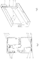
- Fig. 1 is a ground plan of a house which is fitted with a number of ventilating units according to the present invention.
- Fig. 2 is a larger-scale front view of a ventilating unit according to the invention, which is installed between an outside wall and a heating element.
- Fig. 3 is a side view of the unit of Fig. 2.
- Fig. 4 is a view which corresponds with Fig. 3, without the outside wall, however, wherein the air flow through the ventilating unit and the heating element is shown.
- Fig. 5 is a larger-scale perspective view of a separate ventilating unit.
- Fig. 1 is a ground plan of a house, in which the present invention is used.
- the house has two outside walls 1, on which heating elements 2 are mounted in the various rooms.
- Said heating elements may be independent heating elements, but generally they will form part of a central heating system, and in that case the heating elements 2 will consist of radiators, in which water heated by a boiler provides the supply of heat.
- a passage 3 has been formed in the outside wall 1 at the location of each heating element 2, which passage functions to pass outside air through the outside wall 1 into the interior of the house for the purpose of ventilating the house.
- Each passage 3 gives way to a ventilating unit 4, which is disposed between outside wall 1 and heating element 2 in this case.
- the exhaust of air takes place via exhaust channels 12, which may or may not be fitted with an exhaust fan.
- ventilating unit 4 is provided with a passageway 5, which extends between passage 3 in outside wall 1 and the bottom side of the associated heating element 2 when the ventilating unit 4 is installed.
- Heating element 2 is internally provided with a vertical passage 6, so that rising air can be heated from two side over a long distance before it enters the room of the house or other type of building.
- ventilating unit 4 is fitted with a (preferably electronic) control unit 7 (Fig. 5), to which control means, in this case in the form of a valve 8, are connected.
- the valve may be capable of stepless operation, or it may close or open the passageway 5 of ventilating unit 4 partially or entirely in a number of steps.
- the control unit is set for controlling valve 8 on the basis of the pressure difference between the inner side and the outer side of outside wall 1 of the house, in order to obtain a constant flow of outside air when pressure differences vary.
- passageway 5 of ventilating unit 4 comprises an upward portion 5' and a downward portion 5'', and slide valve or rotary valve 8 is provided near the transition between the two portions 5' and 5''.
- the valve is driven by means of an electric motor 9, which is connected to control unit 7, or by another drive unit for adjusting the valve 8.
- Ventilating unit 4 is fitted with a sensor 10, which is capable of measuring the pressure difference between the two sides of the outside wall, on the basis of which pressure difference valve 8 is controlled so as to obtain a desired air flow, for example a more constant or less constant air flow.
- Ventilating unit 4 is to that end provided with a temperature sensor 11, which is mounted near the place where the heated air exits heating element 2, in this case near the upper side of heating element 2.
- This temperature sensor 11 makes it possible to ensure that the temperature of the outflowing air will not fall below a preset value, whereby said preset value may for example be a temperature selected from a possible range of 12 - 20°C, for example 15 to 16°C. Usually no draught problems occur with exit temperatures within this range.
- the power for the electric motor 9 and the control unit 7 may be taken from the existing electricity grid, but it is also possible to use a separate direct current power supply, a battery or a solar cell, for this purpose.
- said units may be coupled, and if said units are used in combination with a central heating system, they may also be coupled to the boiler, so that the temperature control of the central heating system takes place in cooperation with the control of the heating unit. All this depends on the particular use. In newly built houses or in office buildings more central facilities can be provided that in existing houses, where one or more ventilating units according to the invention are added later on, for example when carrying out a renovation project. Of course several variations and additions are possible on the basis of the present principle.
- a filter for filtering the inflowing air may be incorporated in ventilating unit 4, said filtering may take place electrostatically, for example, but also mechanically or otherwise.
- the generation of a ventilating flow may take place in a natural manner, but on the other hand it is possible to build in exhaust fans so as to effect mechanical ventilation.
- the ventilating unit may be fitted with means which ensure that the valve will be closed if the supply voltage is cut off, this in order to prevent an undesirable inflow of air and freezing of the water in heating element 2.
- Said means may comprise a capacitor, for example.
- the invention provides a ventilating unit which is capable of providing comfortable and energy-saving ventilation of houses and other buildings, without large investments being required, whilst the ventilating unit can also be built into existing buildings without any difficulty.
Applications Claiming Priority (2)
| Application Number | Priority Date | Filing Date | Title |
|---|---|---|---|
| NL1005429A NL1005429C2 (nl) | 1997-03-04 | 1997-03-04 | Ventilatie-eenheid. |
| NL1005429 | 1997-03-04 |
Publications (2)
| Publication Number | Publication Date |
|---|---|
| EP0863371A1 true EP0863371A1 (de) | 1998-09-09 |
| EP0863371B1 EP0863371B1 (de) | 2004-12-22 |
Family
ID=19764525
Family Applications (1)
| Application Number | Title | Priority Date | Filing Date |
|---|---|---|---|
| EP98200635A Expired - Lifetime EP0863371B1 (de) | 1997-03-04 | 1998-03-02 | Belüftungseinheit |
Country Status (4)
| Country | Link |
|---|---|
| EP (1) | EP0863371B1 (de) |
| AT (1) | ATE285550T1 (de) |
| DE (1) | DE69828211T2 (de) |
| NL (1) | NL1005429C2 (de) |
Families Citing this family (2)
| Publication number | Priority date | Publication date | Assignee | Title |
|---|---|---|---|---|
| EP1482253A3 (de) | 2003-05-21 | 2010-01-13 | Buva Rationele Bouwprodukten Bv | Verfahren und Vorrichtung zur Lüftung eines Gebäudes |
| AT504937B1 (de) | 2007-02-28 | 2009-10-15 | Rettig Icc Bv | Einrichtung für die zuführung von luft |
Citations (7)
| Publication number | Priority date | Publication date | Assignee | Title |
|---|---|---|---|---|
| US1442831A (en) * | 1921-08-27 | 1923-01-23 | Clarence C Shipp | Heating and ventilating unit |
| US1559767A (en) * | 1922-07-29 | 1925-11-03 | Thomas F O'herron | Direct-indirect heating and ventilating apparatus |
| GB1431671A (en) * | 1972-03-24 | 1976-04-14 | Rickenbach H | Space heating and ventilating system |
| WO1986004667A1 (en) * | 1985-02-08 | 1986-08-14 | Ab Fellingsbro Verkstäder | Apparatus for preheating fresh air |
| DE3632268A1 (de) * | 1986-09-23 | 1988-04-07 | Alois Laternser | Verfahren und vorrichtung zum belueften eines raumes |
| CH668829A5 (en) * | 1985-12-11 | 1989-01-31 | Sigrist Ag Dr | Regulating air conditioning with long delay time constant - compensating for barometric pressure variations with controlled ventilation having reference system delay for max. medicinal benefit |
| US5257958A (en) * | 1993-02-11 | 1993-11-02 | Rapid Engineering, Inc. | Pressure override control for air treatment unit |
-
1997
- 1997-03-04 NL NL1005429A patent/NL1005429C2/nl not_active IP Right Cessation
-
1998
- 1998-03-02 EP EP98200635A patent/EP0863371B1/de not_active Expired - Lifetime
- 1998-03-02 AT AT98200635T patent/ATE285550T1/de not_active IP Right Cessation
- 1998-03-02 DE DE69828211T patent/DE69828211T2/de not_active Expired - Lifetime
Patent Citations (7)
| Publication number | Priority date | Publication date | Assignee | Title |
|---|---|---|---|---|
| US1442831A (en) * | 1921-08-27 | 1923-01-23 | Clarence C Shipp | Heating and ventilating unit |
| US1559767A (en) * | 1922-07-29 | 1925-11-03 | Thomas F O'herron | Direct-indirect heating and ventilating apparatus |
| GB1431671A (en) * | 1972-03-24 | 1976-04-14 | Rickenbach H | Space heating and ventilating system |
| WO1986004667A1 (en) * | 1985-02-08 | 1986-08-14 | Ab Fellingsbro Verkstäder | Apparatus for preheating fresh air |
| CH668829A5 (en) * | 1985-12-11 | 1989-01-31 | Sigrist Ag Dr | Regulating air conditioning with long delay time constant - compensating for barometric pressure variations with controlled ventilation having reference system delay for max. medicinal benefit |
| DE3632268A1 (de) * | 1986-09-23 | 1988-04-07 | Alois Laternser | Verfahren und vorrichtung zum belueften eines raumes |
| US5257958A (en) * | 1993-02-11 | 1993-11-02 | Rapid Engineering, Inc. | Pressure override control for air treatment unit |
Also Published As
| Publication number | Publication date |
|---|---|
| DE69828211T2 (de) | 2005-12-15 |
| DE69828211D1 (de) | 2005-01-27 |
| ATE285550T1 (de) | 2005-01-15 |
| EP0863371B1 (de) | 2004-12-22 |
| NL1005429C2 (nl) | 1998-09-07 |
Similar Documents
| Publication | Publication Date | Title |
|---|---|---|
| KR102056470B1 (ko) | 실내 환경 제어 시스템 | |
| EP2609375B1 (de) | Methode zur regelung eines lüftungssystem für einen raum und lüftungssystem | |
| US6378317B1 (en) | Air-conditioning method and device | |
| KR101121209B1 (ko) | 하이브리드 환기설비 | |
| WO2007094774A1 (en) | Energy efficient house ventilation | |
| WO2018004768A1 (en) | Environmental control and air distribution system and method of using the same | |
| FI64714B (fi) | Ventilations- och vaermeapparat | |
| KR101672838B1 (ko) | 고층건물의 에너지 절약형 통풍 시스템 | |
| KR20090037228A (ko) | 에너지 절약형 전자동 공기조화기 | |
| KR100893835B1 (ko) | 하이브리드 공조시스템 및 그 공조시스템을 이용한공조방법 | |
| US7063140B1 (en) | Multiple climate air system | |
| GB2486471A (en) | Adjustable ventilator for mounting at a roof of a building | |
| JP4392508B2 (ja) | 自然対流式床下暖房換気システム | |
| JP7228371B2 (ja) | 空調システム | |
| US20060172687A1 (en) | Ventilation system | |
| EP0863371B1 (de) | Belüftungseinheit | |
| NL8403660A (nl) | Luchtverversingsinrichting voor gebouwen, in het bijzonder tochtvrij gemaakte gebouwen. | |
| GB2455813A (en) | Combined natural light and ventilation duct | |
| JP4687984B2 (ja) | 空調設備の制御方法 | |
| WO2006018675A1 (en) | Ventilator with fresh air capability together with heating and/or cooling capability and methods for operating such ventilator | |
| KR101385584B1 (ko) | 지능형 전력망을 이용한 실내의 냉난방과 기압 자동 제어 시스템 | |
| KR20120037571A (ko) | 발코니 결로방지 및 제습장치 | |
| JP2005009796A (ja) | 換気量制御方法 | |
| USRE26430E (en) | Beeler air conditioning system | |
| EP4361517A1 (de) | Dynamisch isolierende wandanordnung und entsprechendes kontrollverfahren |
Legal Events
| Date | Code | Title | Description |
|---|---|---|---|
| PUAI | Public reference made under article 153(3) epc to a published international application that has entered the european phase |
Free format text: ORIGINAL CODE: 0009012 |
|
| AK | Designated contracting states |
Kind code of ref document: A1 Designated state(s): AT BE CH DE DK FI FR GB IE IT LI LU NL SE |
|
| AX | Request for extension of the european patent |
Free format text: AL;LT;LV;MK;RO;SI |
|
| 17P | Request for examination filed |
Effective date: 19990217 |
|
| AKX | Designation fees paid |
Free format text: AT BE CH DE DK FI FR GB IE IT LI LU NL SE |
|
| RBV | Designated contracting states (corrected) |
Designated state(s): AT BE CH DE DK FI FR GB IE IT LI LU NL SE |
|
| 17Q | First examination report despatched |
Effective date: 20020124 |
|
| RAP1 | Party data changed (applicant data changed or rights of an application transferred) |
Owner name: GENTLE VENT B.V |
|
| GRAP | Despatch of communication of intention to grant a patent |
Free format text: ORIGINAL CODE: EPIDOSNIGR1 |
|
| GRAS | Grant fee paid |
Free format text: ORIGINAL CODE: EPIDOSNIGR3 |
|
| GRAA | (expected) grant |
Free format text: ORIGINAL CODE: 0009210 |
|
| AK | Designated contracting states |
Kind code of ref document: B1 Designated state(s): AT BE CH DE DK FI FR GB IE IT LI LU NL SE |
|
| PG25 | Lapsed in a contracting state [announced via postgrant information from national office to epo] |
Ref country code: LI Free format text: LAPSE BECAUSE OF FAILURE TO SUBMIT A TRANSLATION OF THE DESCRIPTION OR TO PAY THE FEE WITHIN THE PRESCRIBED TIME-LIMIT Effective date: 20041222 Ref country code: IT Free format text: LAPSE BECAUSE OF FAILURE TO SUBMIT A TRANSLATION OF THE DESCRIPTION OR TO PAY THE FEE WITHIN THE PRESCRIBED TIME-LIMIT;WARNING: LAPSES OF ITALIAN PATENTS WITH EFFECTIVE DATE BEFORE 2007 MAY HAVE OCCURRED AT ANY TIME BEFORE 2007. THE CORRECT EFFECTIVE DATE MAY BE DIFFERENT FROM THE ONE RECORDED. Effective date: 20041222 Ref country code: FI Free format text: LAPSE BECAUSE OF FAILURE TO SUBMIT A TRANSLATION OF THE DESCRIPTION OR TO PAY THE FEE WITHIN THE PRESCRIBED TIME-LIMIT Effective date: 20041222 Ref country code: CH Free format text: LAPSE BECAUSE OF FAILURE TO SUBMIT A TRANSLATION OF THE DESCRIPTION OR TO PAY THE FEE WITHIN THE PRESCRIBED TIME-LIMIT Effective date: 20041222 Ref country code: AT Free format text: LAPSE BECAUSE OF FAILURE TO SUBMIT A TRANSLATION OF THE DESCRIPTION OR TO PAY THE FEE WITHIN THE PRESCRIBED TIME-LIMIT Effective date: 20041222 |
|
| REG | Reference to a national code |
Ref country code: GB Ref legal event code: FG4D |
|
| BECA | Be: change of holder's address |
Owner name: *GENTLE VENT B.V.OSLOFJORDWEG 40, NL-1033 SM AMSTE Effective date: 20041222 |
|
| REG | Reference to a national code |
Ref country code: CH Ref legal event code: EP |
|
| REG | Reference to a national code |
Ref country code: IE Ref legal event code: FG4D |
|
| REF | Corresponds to: |
Ref document number: 69828211 Country of ref document: DE Date of ref document: 20050127 Kind code of ref document: P |
|
| PG25 | Lapsed in a contracting state [announced via postgrant information from national office to epo] |
Ref country code: LU Free format text: LAPSE BECAUSE OF NON-PAYMENT OF DUE FEES Effective date: 20050302 Ref country code: IE Free format text: LAPSE BECAUSE OF NON-PAYMENT OF DUE FEES Effective date: 20050302 |
|
| RAP2 | Party data changed (patent owner data changed or rights of a patent transferred) |
Owner name: GENTLE VENT B.V |
|
| PG25 | Lapsed in a contracting state [announced via postgrant information from national office to epo] |
Ref country code: SE Free format text: LAPSE BECAUSE OF FAILURE TO SUBMIT A TRANSLATION OF THE DESCRIPTION OR TO PAY THE FEE WITHIN THE PRESCRIBED TIME-LIMIT Effective date: 20050322 Ref country code: DK Free format text: LAPSE BECAUSE OF FAILURE TO SUBMIT A TRANSLATION OF THE DESCRIPTION OR TO PAY THE FEE WITHIN THE PRESCRIBED TIME-LIMIT Effective date: 20050322 |
|
| PGFP | Annual fee paid to national office [announced via postgrant information from national office to epo] |
Ref country code: NL Payment date: 20050331 Year of fee payment: 8 |
|
| NLT2 | Nl: modifications (of names), taken from the european patent patent bulletin |
Owner name: GENTLE VENT B.V |
|
| REG | Reference to a national code |
Ref country code: CH Ref legal event code: PL |
|
| PLBI | Opposition filed |
Free format text: ORIGINAL CODE: 0009260 |
|
| PG25 | Lapsed in a contracting state [announced via postgrant information from national office to epo] |
Ref country code: NL Free format text: LAPSE BECAUSE OF NON-PAYMENT OF DUE FEES Effective date: 20051001 |
|
| PLAX | Notice of opposition and request to file observation + time limit sent |
Free format text: ORIGINAL CODE: EPIDOSNOBS2 |
|
| 26 | Opposition filed |
Opponent name: INNOSOURCE B.V. Effective date: 20050921 |
|
| NLV4 | Nl: lapsed or anulled due to non-payment of the annual fee |
Effective date: 20051001 |
|
| REG | Reference to a national code |
Ref country code: IE Ref legal event code: MM4A |
|
| ET | Fr: translation filed | ||
| PLAF | Information modified related to communication of a notice of opposition and request to file observations + time limit |
Free format text: ORIGINAL CODE: EPIDOSCOBS2 |
|
| NLXE | Nl: other communications concerning ep-patents (part 3 heading xe) |
Free format text: PAT. BUL. 12/2005: PATENTNUMBER 0863371 SHOULD BE DELETED. PATENTNUMBER 0863371 HAS BEEN RESTORE TO THE PRIOR STATE. |
|
| PLAF | Information modified related to communication of a notice of opposition and request to file observations + time limit |
Free format text: ORIGINAL CODE: EPIDOSCOBS2 |
|
| NLV6 | Nl: european patent surrendered (cf. article 48 or article 63 of the patents act 1995) | ||
| PLBB | Reply of patent proprietor to notice(s) of opposition received |
Free format text: ORIGINAL CODE: EPIDOSNOBS3 |
|
| PLCK | Communication despatched that opposition was rejected |
Free format text: ORIGINAL CODE: EPIDOSNREJ1 |
|
| PLAG | Information modified related to despatch of communication that opposition is rejected |
Free format text: ORIGINAL CODE: EPIDOSCREJ1 |
|
| APBP | Date of receipt of notice of appeal recorded |
Free format text: ORIGINAL CODE: EPIDOSNNOA2O |
|
| APAH | Appeal reference modified |
Free format text: ORIGINAL CODE: EPIDOSCREFNO |
|
| APBQ | Date of receipt of statement of grounds of appeal recorded |
Free format text: ORIGINAL CODE: EPIDOSNNOA3O |
|
| 29U | Proceedings interrupted after grant according to rule 142 epc |
Effective date: 20090303 |
|
| 29W | Proceedings resumed after grant [after interruption of proceedings according to rule 142 epc] |
Effective date: 20091102 |
|
| APBU | Appeal procedure closed |
Free format text: ORIGINAL CODE: EPIDOSNNOA9O |
|
| PLBN | Opposition rejected |
Free format text: ORIGINAL CODE: 0009273 |
|
| STAA | Information on the status of an ep patent application or granted ep patent |
Free format text: STATUS: OPPOSITION REJECTED |
|
| 27O | Opposition rejected |
Effective date: 20090908 |
|
| PGFP | Annual fee paid to national office [announced via postgrant information from national office to epo] |
Ref country code: FR Payment date: 20100401 Year of fee payment: 13 |
|
| PGFP | Annual fee paid to national office [announced via postgrant information from national office to epo] |
Ref country code: GB Payment date: 20100224 Year of fee payment: 13 |
|
| PGFP | Annual fee paid to national office [announced via postgrant information from national office to epo] |
Ref country code: DE Payment date: 20100305 Year of fee payment: 13 Ref country code: BE Payment date: 20100330 Year of fee payment: 13 |
|
| BERE | Be: lapsed |
Owner name: *GENTLE VENT B.V. Effective date: 20110331 |
|
| GBPC | Gb: european patent ceased through non-payment of renewal fee |
Effective date: 20110302 |
|
| REG | Reference to a national code |
Ref country code: FR Ref legal event code: ST Effective date: 20111130 |
|
| PG25 | Lapsed in a contracting state [announced via postgrant information from national office to epo] |
Ref country code: BE Free format text: LAPSE BECAUSE OF NON-PAYMENT OF DUE FEES Effective date: 20110331 |
|
| PG25 | Lapsed in a contracting state [announced via postgrant information from national office to epo] |
Ref country code: DE Free format text: LAPSE BECAUSE OF NON-PAYMENT OF DUE FEES Effective date: 20111001 Ref country code: FR Free format text: LAPSE BECAUSE OF NON-PAYMENT OF DUE FEES Effective date: 20110331 |
|
| REG | Reference to a national code |
Ref country code: DE Ref legal event code: R119 Ref document number: 69828211 Country of ref document: DE Effective date: 20111001 |
|
| PG25 | Lapsed in a contracting state [announced via postgrant information from national office to epo] |
Ref country code: GB Free format text: LAPSE BECAUSE OF NON-PAYMENT OF DUE FEES Effective date: 20110302 |