EP0863265A2 - Flush mountable fitting - Google Patents
Flush mountable fitting Download PDFInfo
- Publication number
- EP0863265A2 EP0863265A2 EP98103776A EP98103776A EP0863265A2 EP 0863265 A2 EP0863265 A2 EP 0863265A2 EP 98103776 A EP98103776 A EP 98103776A EP 98103776 A EP98103776 A EP 98103776A EP 0863265 A2 EP0863265 A2 EP 0863265A2
- Authority
- EP
- European Patent Office
- Prior art keywords
- control device
- measuring device
- connection
- piece
- fitting according
- Prior art date
- Legal status (The legal status is an assumption and is not a legal conclusion. Google has not performed a legal analysis and makes no representation as to the accuracy of the status listed.)
- Withdrawn
Links
- 239000000463 material Substances 0.000 claims description 3
- 229910001369 Brass Inorganic materials 0.000 claims description 2
- 239000010951 brass Substances 0.000 claims description 2
- 238000009435 building construction Methods 0.000 claims description 2
- 238000009434 installation Methods 0.000 claims description 2
- XLYOFNOQVPJJNP-UHFFFAOYSA-N water Substances O XLYOFNOQVPJJNP-UHFFFAOYSA-N 0.000 abstract description 2
- 239000011505 plaster Substances 0.000 abstract 1
- 238000005219 brazing Methods 0.000 description 1
- 230000007797 corrosion Effects 0.000 description 1
- 238000005260 corrosion Methods 0.000 description 1
Images


Classifications
-
- E—FIXED CONSTRUCTIONS
- E03—WATER SUPPLY; SEWERAGE
- E03B—INSTALLATIONS OR METHODS FOR OBTAINING, COLLECTING, OR DISTRIBUTING WATER
- E03B7/00—Water main or service pipe systems
- E03B7/07—Arrangement of devices, e.g. filters, flow controls, measuring devices, siphons or valves, in the pipe systems
- E03B7/072—Arrangement of flowmeters
-
- E—FIXED CONSTRUCTIONS
- E03—WATER SUPPLY; SEWERAGE
- E03B—INSTALLATIONS OR METHODS FOR OBTAINING, COLLECTING, OR DISTRIBUTING WATER
- E03B7/00—Water main or service pipe systems
- E03B7/07—Arrangement of devices, e.g. filters, flow controls, measuring devices, siphons or valves, in the pipe systems
- E03B7/078—Combined units with different devices; Arrangement of different devices with respect to each other
-
- E—FIXED CONSTRUCTIONS
- E03—WATER SUPPLY; SEWERAGE
- E03B—INSTALLATIONS OR METHODS FOR OBTAINING, COLLECTING, OR DISTRIBUTING WATER
- E03B7/00—Water main or service pipe systems
- E03B7/07—Arrangement of devices, e.g. filters, flow controls, measuring devices, siphons or valves, in the pipe systems
- E03B7/08—Arrangement of draining devices, e.g. manual shut-off valves
Definitions
- the invention relates to a concealed fitting for water piping in the sanitary installation in the Building construction, comprising a measuring device, in particular a Dial indicator, and a control device, in particular a Shut-off valve.
- the present invention is based on the object Concealed fitting to improve that Installer takes less time to assemble and that one more compact design and less tendency to Leakage is achieved.
- measuring device and control device dispenses with an intermediate pipe section, so that in the one-piece training one Housing body no connection point at all Measuring device and control device more that would have to be sealed.
- the direct connection of measuring device or housing of the measuring device with the Control device which is preferably done by brazing, there is only a single connection between Measuring device and control device.
- the connections or Connection areas of measuring device and control device are preferably brazed together.
- screw connections also conceivable. This can on the one hand compact design can be achieved because less space for the arrangement of the concealed fitting is required. Through the fewer connection points are also fewer possible leakage points exist.
- the Measuring device have a connecting flange into which a Connection piece of the control device engages.
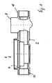
- Figure 1 shows a concealed fitting with one piece trained hot-pressed housing base 2, the one Housing 4 for receiving one not in the figures shown measuring insert to form the measuring device 6 and a control device 8 in the form of a shut-off valve forms.
- the housing base body 2 has on the side of the Control device 8 has a flange-shaped connection section 10 in which a free end of a feed line by means of a suitable connector can be screwed in.
- On the Side of the measuring device 6 is a corresponding one flange-shaped connecting section 12 is provided.
- FIG 2 shows a further embodiment of the Concealed fitting according to the invention, which differs from that in FIG 1 differs in that it does not has one-piece housing base body, but that a Housing 14 of the measuring device 6 'directly with a Housing 16 of the control device 8 'is brazed. Therefor the housing 14 has a connecting flange 18 into which a Connection piece 20 engages and is brazed.
- Figure 3 is a plan view of a common one Cover rosette 22 shown, the openings 24 and 26 a upstanding flange-shaped edge portion 28 of the Measuring device 6, 6 'and a dome-shaped section 30 of the Control device 8, 8 'can accommodate if the Cover rosette on the embedded in the plastered wall Device is placed.
Landscapes
- Health & Medical Sciences (AREA)
- Life Sciences & Earth Sciences (AREA)
- Engineering & Computer Science (AREA)
- Hydrology & Water Resources (AREA)
- Public Health (AREA)
- Water Supply & Treatment (AREA)
- Measuring Volume Flow (AREA)
- Domestic Plumbing Installations (AREA)
Abstract
Description
Die Erfindung betrifft eine Unterputzarmatur für wasserführende Verrohrung bei der Sanitärinstallation im Gebäudebau, umfassend eine Messvorrichtung, insbesondere eine Messuhr, und eine Steuervorrichtung, insbesondere ein Absperrventil.The invention relates to a concealed fitting for water piping in the sanitary installation in the Building construction, comprising a measuring device, in particular a Dial indicator, and a control device, in particular a Shut-off valve.
Üblicherweise werden eine Messvorrichtung und eine Steuervorrichtung bei der Wand- oder Schachtmontage über ein Rohrstück miteinander verbunden. Hierbei sind vier mögliche Leckagestellen gegeben, und zwar zwischen der Verrohrung und der Messvorrichtung, zwischen der Messvorrichtung und dem Rohrstück, zwischen dem Rohrstück und der Steuervorrichtung und schließlich zwischen der Steuervorrichtung und der zuführenden Leitung der Verrohrung. Usually a measuring device and a Control device for wall or shaft mounting via one Pipe piece connected together. Here are four possible ones Leakage points exist, between the piping and the measuring device, between the measuring device and the Pipe piece, between the pipe piece and the control device and finally between the control device and the supplying piping.
Der vorliegenden Erfindung liegt die Aufgabe zugrunde, die Unterputzarmatur dahingehend zu verbessern, dass ein Installateur weniger Zeit zur Montage benötigt und dass eine kompaktere Bauweise sowie eine geringere Neigung zum Leckwerden erreicht wird.The present invention is based on the object Concealed fitting to improve that Installer takes less time to assemble and that one more compact design and less tendency to Leakage is achieved.
Diese Aufgabe wird bei einer Unterputzarmatur der genannten Art erfindungsgemäß dadurch gelöst, dass eine Messvorrichtung bzw. ein Gehäuse für die Aufnahme eines Messeinsatzes einstückig mit der Steuervorrichtung ausgebildet ist oder dass ein Anschluss der Messvorrichtung unmittelbar mit einem Anschluss der Steuervorrichtung verbunden ist.This task is mentioned in a concealed fitting Art solved according to the invention in that a measuring device or a housing for holding a measuring insert is integrally formed with the control device or that a connection of the measuring device directly with a Connection of the control device is connected.
Es wird also erfindungsgemäß auf ein zwischen Messvorrichtung und Steuervorrichtung zwischengeordnetes Rohrstück verzichtet, so dass bei der einstückigen Ausbildung eines Gehäusegrundkörpers überhaupt keine Verbindungsstelle zwischen Messvorrichtung und Steuervorrichtung mehr besteht, die abgedichtet werden müsste. Bei der unmittelbaren Verbindung von Messvorrichtung oder Gehäuse der Messvorrichtung mit der Steuervorrichtung, was vorzugsweise durch Hartlöten erfolgt, besteht nur noch eine einzige Verbindungsstelle zwischen Messvorrichtung und Steuervorrichtung. Die Anschlüsse oder Anschlussbereiche von Messvorrichtung und Steuervorrichtung werden vorzugsweise miteinander hart verlötet. Es sind jedoch auch Verschraubungen denkbar. Hierdurch kann einerseits eine kompaktere Bauweise erreicht werden, da weniger Bauraum für die Anordnung der Unterputzarmatur benötigt wird. Durch die geringere Anzahl von Verbindungsstellen sind auch weniger mögliche Leckagestellen vorhanden.According to the invention, it is therefore a between measuring device and control device dispenses with an intermediate pipe section, so that in the one-piece training one Housing body no connection point at all Measuring device and control device more that would have to be sealed. With the direct connection of measuring device or housing of the measuring device with the Control device, which is preferably done by brazing, there is only a single connection between Measuring device and control device. The connections or Connection areas of measuring device and control device are preferably brazed together. However, there are screw connections also conceivable. This can on the one hand compact design can be achieved because less space for the arrangement of the concealed fitting is required. Through the fewer connection points are also fewer possible leakage points exist.
Bei nicht einstückiger Ausbildung der Vorrichtung kann die Messvorrichtung einen Anschlussflansch aufweisen, in den ein Anschlussstutzen der Steuervorrichtung eingreift.If the device is not formed in one piece, the Measuring device have a connecting flange into which a Connection piece of the control device engages.
Wenn die Messvorrichtung und die Steuervorrichtung aus demselben Material, insbesondere aus Messing, gefertigt sind, ergeben sich auch keine Probleme im Hinblick auf Korrosion in folge unterschiedlicher elektrochemischer Potentiale der Materialien.When the measuring device and the control device off the same material, in particular made of brass, there are also no problems with corrosion in follow different electrochemical potentials of the Materials.
Da bei der erfindungsgemäßen Lösung eine genaue relative Anordnung der Messvorrichtung und der Steuervorrichtung zueinander erreicht wird, lässt sich auch eine einzige die Sichtseite bildende Abdeckrosette für die Messvorrichtung und die Steuervorrichtung verwenden.Since in the solution according to the invention an exact relative Arrangement of the measuring device and the control device is reached to each other, can also be a single Cover rosette for the measuring device and use the control device.
Weitere Merkmale, Einzelheiten und Vorteile der Erfindung ergeben sich aus der zeichnerischen Darstellung und nachfolgenden Beschreibung einer vorteilhaften Ausführungsform der Erfindung. In der Zeichnung zeigt:
Figur 1- eine Schnittansicht einer Unterputzarmatur nach der Erfindung;
Figur 2- eine weitere Ausführungsform einer Unterputzarmatur nach der Erfindung; und
Figur 3- eine Abdeckrosette für die Vorrichtung nach
Figur 1.
- Figure 1
- a sectional view of a concealed fitting according to the invention;
- Figure 2
- a further embodiment of a concealed fitting according to the invention; and
- Figure 3
- a cover rosette for the device of Figure 1.
Figur 1 zeigt eine Unterputzarmatur mit einem einstückig
ausgebildeten warm gepressten Gehäusegrundkörper 2, der ein
Gehäuse 4 für die Aufnahme eines in den Figuren nicht
dargestellten Messeinsatzes zur Ausbildung der Messvorrichtung
6 sowie eine Steuervorrichtung 8 in Form eines Absperrventils
bildet. Der Gehäusegrundkörper 2 weist auf der Seite der
Steuervorrichtung 8 einen flanschförmigen Anschlussabschnitt
10 auf, in den ein freies Ende einer Zuführleitung mittels
eines geeigneten Anschlussstücks einschraubbar ist. Auf der
Seite der Messvorrichtung 6 ist ein entsprechender
flanschförmiger Anschlussabschnitt 12 vorgesehen.Figure 1 shows a concealed fitting with one piece
trained hot-pressed
Figur 2 zeigt eine weitere Ausführungsform der
erfindungsgemäßen Unterputzarmatur, die sich von der in Figur
1 dargestellten dadurch unterscheidet, dass sie keinen
einstückigen Gehäusegrundkörper aufweist, sondern dass ein
Gehäuse 14 der Messvorrichtung 6' unmittelbar mit einem
Gehäuse 16 der Steuervorrichtung 8' hart verlötet ist. Hierfür
weist das Gehäuse 14 einen Anschlussflansch 18 auf, in den ein
Anschlussstutzen 20 eingreift und hart verlötet ist. Figure 2 shows a further embodiment of the
Concealed fitting according to the invention, which differs from that in FIG
1 differs in that it does not
has one-piece housing base body, but that a
In Figur 3 ist eine Draufsicht auf eine gemeinsame
Abdeckrosette 22 dargestellt, deren Öffnungen 24 und 26 einen
nach oben stehenden flanschförmigen Randabschnitt 28 der
Messvorrichtung 6, 6' sowie einen domförmigen Abschnitt 30 der
Steuervorrichtung 8, 8' aufnehmen können, wenn die
Abdeckrosette auf die in die verputzte Wand eingelassene
Vorrichtung aufgesetzt wird.In Figure 3 is a plan view of a common one
Claims (6)
Applications Claiming Priority (2)
| Application Number | Priority Date | Filing Date | Title |
|---|---|---|---|
| DE1997108920 DE19708920B4 (en) | 1997-03-05 | 1997-03-05 | Concealed fitting |
| DE19708920 | 1997-03-05 |
Publications (2)
| Publication Number | Publication Date |
|---|---|
| EP0863265A2 true EP0863265A2 (en) | 1998-09-09 |
| EP0863265A3 EP0863265A3 (en) | 1999-01-20 |
Family
ID=7822281
Family Applications (1)
| Application Number | Title | Priority Date | Filing Date |
|---|---|---|---|
| EP98103776A Withdrawn EP0863265A3 (en) | 1997-03-05 | 1998-03-04 | Flush mountable fitting |
Country Status (2)
| Country | Link |
|---|---|
| EP (1) | EP0863265A3 (en) |
| DE (1) | DE19708920B4 (en) |
Cited By (2)
| Publication number | Priority date | Publication date | Assignee | Title |
|---|---|---|---|---|
| EP1318243A1 (en) * | 2001-12-04 | 2003-06-11 | Minol International GmbH & Co. KG | Device for flush-mounting sanitary fittings |
| EP1416097A1 (en) * | 2002-10-30 | 2004-05-06 | Geberit Technik Ag | Connection device for water piping in sanitary installations |
Families Citing this family (1)
| Publication number | Priority date | Publication date | Assignee | Title |
|---|---|---|---|---|
| DE202017101482U1 (en) * | 2017-03-14 | 2018-06-15 | Hans Sasserath Gmbh & Co Kg | Modular kit for water fittings |
Citations (6)
| Publication number | Priority date | Publication date | Assignee | Title |
|---|---|---|---|---|
| FR2298751A1 (en) * | 1975-01-21 | 1976-08-20 | Nussbaum & Co Ag R | Valve with two shut-off members or one member and filter - has common housing with parallel connections for each member or filter |
| US4665941A (en) * | 1981-03-27 | 1987-05-19 | Hudson David R | Fluid control of metering assemblies |
| DE9013788U1 (en) * | 1990-10-04 | 1990-12-06 | Techem Gmbh, 6000 Frankfurt, De | |
| GB2261734A (en) * | 1991-11-23 | 1993-05-26 | Reliance Water Controls Limite | Water metering unit |
| WO1995031664A1 (en) * | 1994-05-11 | 1995-11-23 | Philippe Persohn | Valve/seal assembly and use thereof, in particular in a water metering unit |
| DE29519416U1 (en) * | 1995-12-07 | 1996-01-25 | Kemper Gmbh & Co Metallwerke G | Arrangement of line fittings in piping systems |
Family Cites Families (5)
| Publication number | Priority date | Publication date | Assignee | Title |
|---|---|---|---|---|
| DE7210065U (en) * | 1971-04-20 | 1972-06-29 | Bosco & C. S.p.A., Turin (Italien) | FITTING THAT CAN BE INSERTED IN A PIPE CONTAINING A LIQUID OR GAS |
| DE3308347C2 (en) * | 1983-03-09 | 1995-03-23 | Siegfried Boehnisch | Branch and shut-off device for cold water supply networks |
| IT1204669B (en) * | 1987-05-29 | 1989-03-10 | Antonio Romanelli | BUILT-IN WATER UNIT FOR THE SUPPLY OF WATER TO SANITARY ITEMS |
| DE19525358C2 (en) * | 1995-07-12 | 1997-10-02 | Werner Schoen | Single lever mixer tap for concealed installation |
| DE29604967U1 (en) * | 1996-03-19 | 1996-06-13 | Eisenwerk Wittigsthal Gmbh | Assembly unit with built-in shut-off device-measuring device combination |
-
1997
- 1997-03-05 DE DE1997108920 patent/DE19708920B4/en not_active Expired - Lifetime
-
1998
- 1998-03-04 EP EP98103776A patent/EP0863265A3/en not_active Withdrawn
Patent Citations (6)
| Publication number | Priority date | Publication date | Assignee | Title |
|---|---|---|---|---|
| FR2298751A1 (en) * | 1975-01-21 | 1976-08-20 | Nussbaum & Co Ag R | Valve with two shut-off members or one member and filter - has common housing with parallel connections for each member or filter |
| US4665941A (en) * | 1981-03-27 | 1987-05-19 | Hudson David R | Fluid control of metering assemblies |
| DE9013788U1 (en) * | 1990-10-04 | 1990-12-06 | Techem Gmbh, 6000 Frankfurt, De | |
| GB2261734A (en) * | 1991-11-23 | 1993-05-26 | Reliance Water Controls Limite | Water metering unit |
| WO1995031664A1 (en) * | 1994-05-11 | 1995-11-23 | Philippe Persohn | Valve/seal assembly and use thereof, in particular in a water metering unit |
| DE29519416U1 (en) * | 1995-12-07 | 1996-01-25 | Kemper Gmbh & Co Metallwerke G | Arrangement of line fittings in piping systems |
Cited By (2)
| Publication number | Priority date | Publication date | Assignee | Title |
|---|---|---|---|---|
| EP1318243A1 (en) * | 2001-12-04 | 2003-06-11 | Minol International GmbH & Co. KG | Device for flush-mounting sanitary fittings |
| EP1416097A1 (en) * | 2002-10-30 | 2004-05-06 | Geberit Technik Ag | Connection device for water piping in sanitary installations |
Also Published As
| Publication number | Publication date |
|---|---|
| DE19708920B4 (en) | 2009-04-16 |
| DE19708920A1 (en) | 1998-09-10 |
| EP0863265A3 (en) | 1999-01-20 |
Similar Documents
| Publication | Publication Date | Title |
|---|---|---|
| AT395257B (en) | Sanitary concealed fitting | |
| EP2154297A2 (en) | Shower assembly | |
| EP0061561A1 (en) | Mural mixing value | |
| EP0863265A2 (en) | Flush mountable fitting | |
| DE102012212306A1 (en) | plumbing fixture | |
| EP0378515B1 (en) | Crossing element for connecting a sanitary armature to at least one conduit | |
| EP0419414B1 (en) | Installation unit for a water closet | |
| EP2143847A2 (en) | Tap with built-in wall box | |
| CH646503A5 (en) | KIT FOR RETROFITTING TWO-HANDLE UNDER-MOUNTED FITTINGS. | |
| DE2930518C2 (en) | Device for connecting a line fitting | |
| DE4239801A1 (en) | Wash basin or sink unit with integral tap housing - has housing formed in a recess in sinks surround or sink work area | |
| EP0296470A1 (en) | Water outlet armature | |
| EP0354177B1 (en) | Connecting device for flexible conduits | |
| DE1809022C3 (en) | Wall mixer for cold and hot water | |
| EP3914783B1 (en) | Coupling for fitting | |
| DE19536771C2 (en) | Rainwater harvesting system | |
| EP3454021B1 (en) | Connection piece | |
| EP1416097A1 (en) | Connection device for water piping in sanitary installations | |
| DE3807845C2 (en) | Junction box | |
| EP0357552B1 (en) | Connection device at an inlet valve for a toilet cistern | |
| DE2324023C3 (en) | Concealed connection piece for sanitary fittings | |
| EP0870997B1 (en) | Connecting arrangement for a wall mounted heater | |
| DE102012201693A1 (en) | Adapter element for connecting terminal of surface-mounted sanitary fitting at base block of flush-mounted sanitary fitting, has fixing device fixing connecting pieces to base block, where pieces are connected to apertures of base block | |
| WO2022101292A1 (en) | Apparatus for fixing a sanitary appliance to a wall and sanitary installation having a corresponding apparatus | |
| DE19708921A1 (en) | Installation unit for undercoat control- and measuring devices used in sanitary installations in buildings |
Legal Events
| Date | Code | Title | Description |
|---|---|---|---|
| PUAI | Public reference made under article 153(3) epc to a published international application that has entered the european phase |
Free format text: ORIGINAL CODE: 0009012 |
|
| AK | Designated contracting states |
Kind code of ref document: A2 Designated state(s): AT BE CH DE DK ES FI FR GB GR IE IT LI LU MC NL PT SE |
|
| AX | Request for extension of the european patent |
Free format text: AL;LT;LV;MK;RO;SI |
|
| PUAL | Search report despatched |
Free format text: ORIGINAL CODE: 0009013 |
|
| AK | Designated contracting states |
Kind code of ref document: A3 Designated state(s): AT BE CH DE DK ES FI FR GB GR IE IT LI LU MC NL PT SE |
|
| AX | Request for extension of the european patent |
Free format text: AL;LT;LV;MK;RO;SI |
|
| AKX | Designation fees paid | ||
| STAA | Information on the status of an ep patent application or granted ep patent |
Free format text: STATUS: THE APPLICATION IS DEEMED TO BE WITHDRAWN |
|
| 18D | Application deemed to be withdrawn |
Effective date: 19990721 |
|
| REG | Reference to a national code |
Ref country code: DE Ref legal event code: 8566 |