EP0861997B1 - Handwerkzeugmaschine mit geschmiertem Winkelgetriebe - Google Patents
Handwerkzeugmaschine mit geschmiertem Winkelgetriebe Download PDFInfo
- Publication number
- EP0861997B1 EP0861997B1 EP98850023A EP98850023A EP0861997B1 EP 0861997 B1 EP0861997 B1 EP 0861997B1 EP 98850023 A EP98850023 A EP 98850023A EP 98850023 A EP98850023 A EP 98850023A EP 0861997 B1 EP0861997 B1 EP 0861997B1
- Authority
- EP
- European Patent Office
- Prior art keywords
- lubricant
- gear casing
- receptacle
- power tool
- output shaft
- Prior art date
- Legal status (The legal status is an assumption and is not a legal conclusion. Google has not performed a legal analysis and makes no representation as to the accuracy of the status listed.)
- Expired - Lifetime
Links
- 239000000314 lubricant Substances 0.000 claims description 40
- 230000002093 peripheral effect Effects 0.000 claims description 4
- 239000002184 metal Substances 0.000 claims description 3
- 239000004605 External Lubricant Substances 0.000 claims 1
- 239000004519 grease Substances 0.000 description 6
- 238000005461 lubrication Methods 0.000 description 5
- 230000002745 absorbent Effects 0.000 description 3
- 239000002250 absorbent Substances 0.000 description 3
- 238000010521 absorption reaction Methods 0.000 description 1
- 238000013019 agitation Methods 0.000 description 1
- 230000001627 detrimental effect Effects 0.000 description 1
- 230000005484 gravity Effects 0.000 description 1
- 239000000463 material Substances 0.000 description 1
- 238000013021 overheating Methods 0.000 description 1
- 229920006395 saturated elastomer Polymers 0.000 description 1
- 238000007789 sealing Methods 0.000 description 1
Images
Classifications
-
- B—PERFORMING OPERATIONS; TRANSPORTING
- B25—HAND TOOLS; PORTABLE POWER-DRIVEN TOOLS; MANIPULATORS
- B25F—COMBINATION OR MULTI-PURPOSE TOOLS NOT OTHERWISE PROVIDED FOR; DETAILS OR COMPONENTS OF PORTABLE POWER-DRIVEN TOOLS NOT PARTICULARLY RELATED TO THE OPERATIONS PERFORMED AND NOT OTHERWISE PROVIDED FOR
- B25F5/00—Details or components of portable power-driven tools not particularly related to the operations performed and not otherwise provided for
-
- F—MECHANICAL ENGINEERING; LIGHTING; HEATING; WEAPONS; BLASTING
- F16—ENGINEERING ELEMENTS AND UNITS; GENERAL MEASURES FOR PRODUCING AND MAINTAINING EFFECTIVE FUNCTIONING OF MACHINES OR INSTALLATIONS; THERMAL INSULATION IN GENERAL
- F16H—GEARING
- F16H57/00—General details of gearing
- F16H57/04—Features relating to lubrication or cooling or heating
- F16H57/045—Lubricant storage reservoirs, e.g. reservoirs in addition to a gear sump for collecting lubricant in the upper part of a gear case
-
- F—MECHANICAL ENGINEERING; LIGHTING; HEATING; WEAPONS; BLASTING
- F16—ENGINEERING ELEMENTS AND UNITS; GENERAL MEASURES FOR PRODUCING AND MAINTAINING EFFECTIVE FUNCTIONING OF MACHINES OR INSTALLATIONS; THERMAL INSULATION IN GENERAL
- F16H—GEARING
- F16H57/00—General details of gearing
- F16H57/04—Features relating to lubrication or cooling or heating
- F16H57/0463—Grease lubrication; Drop-feed lubrication
- F16H57/0464—Grease lubrication
-
- F—MECHANICAL ENGINEERING; LIGHTING; HEATING; WEAPONS; BLASTING
- F16—ENGINEERING ELEMENTS AND UNITS; GENERAL MEASURES FOR PRODUCING AND MAINTAINING EFFECTIVE FUNCTIONING OF MACHINES OR INSTALLATIONS; THERMAL INSULATION IN GENERAL
- F16H—GEARING
- F16H57/00—General details of gearing
- F16H57/04—Features relating to lubrication or cooling or heating
- F16H57/048—Type of gearings to be lubricated, cooled or heated
- F16H57/0493—Gearings with spur or bevel gears
- F16H57/0495—Gearings with spur or bevel gears with fixed gear ratio
-
- Y—GENERAL TAGGING OF NEW TECHNOLOGICAL DEVELOPMENTS; GENERAL TAGGING OF CROSS-SECTIONAL TECHNOLOGIES SPANNING OVER SEVERAL SECTIONS OF THE IPC; TECHNICAL SUBJECTS COVERED BY FORMER USPC CROSS-REFERENCE ART COLLECTIONS [XRACs] AND DIGESTS
- Y10—TECHNICAL SUBJECTS COVERED BY FORMER USPC
- Y10S—TECHNICAL SUBJECTS COVERED BY FORMER USPC CROSS-REFERENCE ART COLLECTIONS [XRACs] AND DIGESTS
- Y10S173/00—Tool driving or impacting
- Y10S173/03—Lubrication
Definitions
- the invention relates to a power tool of the type having a rotation motor drivingly connected to an output shaft via an angle drive.
- the invention concerns a power tool of the above type in which the angle drive comprises a gear casing, a bevelled pinion gear connected to the motor, a bevelled crown wheel connected to the output shaft and intermeshing with the pinion gear, and a lubricant dispensing means located in the gear casing and arranged to provide a lubricant to the angle drive.
- the angle drive disclosed in this patent comprises a absorbent sleeve element immovably mounted in the gear casing surrounding the output shaft.
- This sleeve which comprises two portions of different absorption properties, is initially saturated with a lubricant and arranged to meter that lubricant onto the gear teeth of the crown wheel by gravitation.
- a drawback with this device is that a lubricant with comparatively low viscosity has to be used. This means in turn that also when the tool is temporarily out of use or stored for a shorter or longer period of time the lubricant is dispensed continuously from the absorbent sleeve. Thereby, the lubricant may be gathered somewhere in the gear casing where it will not be effective to lubricate the gear when the tool is put back in use.
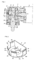
- the power tool shown in Fig.1 comprises a housing 10, a rotation motor (not shown), and an angle gear 11.
- the latter is located in a gear casing 12 attached to the housing 10 and includes a pinion shaft 13 drivingly coupled to the motor, a pinion gear 14, and an output shaft 16.
- a crown wheel 17 is locked to the output shaft 16 by a key 18 and intermeshes with the pinion gear 14.
- the output shaft 16 is journalled in an rear bearing 19 and a forward bearing 20, whereof the rear bearing 19 is supported in a socket portion 22 in the gear casing 12 and the forward bearing 20 is axially supported by a threaded ring element 23 forming an end closure of the gear casing 12.
- the ring element 23 has a central opening 24 through which a drive end 26 of the output shaft 16 protrudes from the gear casing 12, and a seal ring 27 is carried on the ring element 23 for sealing off the opening 24 around the output shaft 16.
- the drive end 26 of the output shaft 16 is adapted to carry any standard type working implement, for instance a grinding tool.
- a cup-shaped lubricant receptacle 28 having an end wall 29 and a peripheral side wall.
- the latter comprises a cylindrical section 30 and a flat section 31.
- the end wall 29 is flat and has a circular opening 32 through which the output shaft 16 extends, .
- the receptacle 28 is intended to be located with the end wall 29 close to the crown wheel 17 and with the flat side wall section 31 oppposite the end surface of the pinion gear 14. See Fig. 1.
- the cylindrical side wall section 30 is divided by slots or openings 35a, 35b and 35c into four axially directed tounges or fingers 36a, 36b, 36c and 36d, each formed at its free upper end with an external circumferentially directed rib 38.
- the latter is intended to cooperate by a snap-action with a circumferential shoulder 39 in the gear casing 12 to axially lock the receptacle 28 in the gear casing 12.
- the shoulder 39 is formed by a part-circumferential groove 40 in the gear casing 12.
- the flat side wall section 31 is not connected to the adjacent tounges 36a, 36d of the cylindrical wall section 30, but leaves the tounges 36a, 36b free to be elastically bent to ensure the snap-action between the ribs 38 and the shoulder 39.
- the slots 35a-c of the cylindrical side wall section 30 are fully covered by a surrounding inner wall 41 of the gear casing 12 to make the receptacle 28 fully cup-shaped.
- the receptacle 28 may be filled up with a lubricant.
- the receptacle 28 is provided with a small size opening 43 through which lubricant is dispensed mainly by gravity onto the crown wheel 17.
- an agitator element in the form of a freely movable metal ball 44. Due to vibrational and other movements of the tool housing 10 and gear casing 12 during operation of the tool, the ball 44 moves around in the receptacle 28 agitating the lubricant and makes the lubricant move in several directions, inter alia in the direction of the outlet opening 43.
- the lubricant is dispensed from the receptacle 28 via the opening 43 onto the gear teeth of the crown wheel 17 to lubricate the angle gear 11.
- the lubricant does not stay on the gear teeth but is thrown off by centrifugal action and is also separated by the rather violent agitation of the gear teeth into its heavier and lighter components.
- the heavier components, which have a higher viscosity, are deposited on the walls of the gear casing 12, whereas the lighter components, which have a lower viscosity, tend to leak out from the gear casing 12 past the output shaft seal ring 27.
- the lubricant receptacle 28 may be made of any suitable material like sheet metal or plastic, and the side wall tounges 36a-d of the receptacle 28 may be varied in number and configuration.
- the invention restricted to a device having an agitator element in the form of a ball 44.
- There may also be more than one agitator element.
- There may also be more than one lubricant outlet opening 43. Accordingly, it is obvious that the number and configuration of the agitator element as well as the location and size of the lubricant outlet may be varied in response to the viscosity properties of the actual type of lubricant.
Landscapes
- Engineering & Computer Science (AREA)
- Mechanical Engineering (AREA)
- General Details Of Gearings (AREA)
- Gear Transmission (AREA)
- Portable Power Tools In General (AREA)
- Percussive Tools And Related Accessories (AREA)
- Lubrication Of Internal Combustion Engines (AREA)
Claims (7)
- Motorwerkzeug mit einem Rotationsmotor, einer rotierenden Ausgangswelle (26) und einem Winkeltrieb (11), der den Motor mit der Ausgangswelle (26) verbindet und ein Getriebegehäuse (12), ein mit dem Motor verbundenes Ritzelzahnrad (14), ein mit der Ausgangswelle (26) verbundenes Kegelzahnrad (17) und Schmiermittel abgebende Mittel (28, 44) besitzt, die in dem Getriebegehäuse (12) angeordnet sind und dazu dienen, den Winkeltrieb (11) mit Schmiermittel zu versorgen, wobei die Schmiermittel abgebenden Mittel (28, 44) ein Schmiermittelbehältnis (28) aufweisen, das eine Umfangsseitenwand (30, 31), die sich im wesentlichen parallel zu der Ausgangswelle (26) erstreckt, und eine Stirnwand (29) besitzt, die im wesentlichen transversal zu der Seitenwand (30, 31) und der Ausgangswelle (26) liegt, dadurch gekennzeichnet, daß das Behältnis (28) in dem Getriebegehäuse (12) unbeweglich gehalten ist, die Stirnwand (29) nahe des Kegelzahnrades (17) angeordnet ist und eine Auslaßöffnung (43) für das Schmiermittel aufweist und daß wenigstens ein Bewegungselement (44) innerhalb des Behältnisses (28) frei beweglich derart angeordnet ist, daß das Schmiermittel unter der Wirkung von im Zusammenhang mit dem Werkzeugbetrieb stehenden Vibrationsbewegungen des Getriebegehäuses (12) bewegt und dadurch das Ausbreiten des Schmiermittels in Richtung der Auslaßöffnung (43) erleichtert wird.
- Motorwerkzeug nach Anspruch 1, dadurch gekennzeichnet, daß das Getriebegehäuse (12) mit sich seitlich erstrekkenden Durchtrittsmitteln (42) versehen ist, um ein Nachfüllen des Behältnisses aus einer außenliegenden Schmiermittelquelle zu ermöglichen.
- Motorwerkzeug nach Anspruch 2, dadurch gekennzeichnet, daß die Umfangsseitenwand (30, 31) des Behältnisses (28) mit einer Einlaßöffnung (35b) für Schmiermittel versehen ist und die Durchtrittsmittel (42) des Getriebegehäuses (12) derart angeordnet sind, daß sie mit der Einlaßöffnung (42) für das Schmiermittel zusammenfallen.
- Motorwerkzeug nach einem der Ansprüche 1 bis 3, dadurch gekennzeichnet, daß das wenigstens eine Bewegungselement (44) aus einer Metallkugel besteht.
- Motorwerkzeug nach einem der Ansprüche 1 bis 4, dadurch gekennzeichnet, daß das Behältnis (28) becherförmig ist und seine Umfangsseitenwand (30, 31) durch Schlitze (35 a - c) in eine Anzahl axial ausgerichteter Zungen (36 a-d) unterteilt ist, die jeweils an ihrem freien Ende mit einer äußeren, in Umfangsrichtung verlaufenden Rippe (38) ausgebildet sind, die zum Zusammenwirken durch Einschnappen mit einem entsprechenden Absatz (39) in dem Getriebegehäuse (12) vorgesehen sind, um das Behältnis (28) in dem Getriebegehäuse (12) axial zu verriegeln.
- Motorwerkzeug nach Anspruch 5, dadurch gekennzeichnet, daß einer der Schlitze (35 b) die Einlaßöffnung für Schmiermittel bildet.
- Motorwerkzeug nach einem der Ansprüche 3 bis 6, dadurch gekennzeichnet, daß ein Schmiernippel (45) in der Durchtrittsöffnung (42) in dem Getriebegehäuse montiert ist, wobei sich der Nippel (45) in die Einlaßöffnung (35 b) für Schmiermittel des Behältnisses (28) erstreckt und dadurch eine Drehverriegelung für das Behältnis (28) bildet.
Applications Claiming Priority (2)
| Application Number | Priority Date | Filing Date | Title |
|---|---|---|---|
| SE9700579 | 1997-02-19 | ||
| SE9700579A SE509564C2 (sv) | 1997-02-19 | 1997-02-19 | Motorverktyg med smord vinkelväxel |
Publications (2)
| Publication Number | Publication Date |
|---|---|
| EP0861997A1 EP0861997A1 (de) | 1998-09-02 |
| EP0861997B1 true EP0861997B1 (de) | 2001-08-08 |
Family
ID=20405848
Family Applications (1)
| Application Number | Title | Priority Date | Filing Date |
|---|---|---|---|
| EP98850023A Expired - Lifetime EP0861997B1 (de) | 1997-02-19 | 1998-02-18 | Handwerkzeugmaschine mit geschmiertem Winkelgetriebe |
Country Status (5)
| Country | Link |
|---|---|
| US (1) | US6109366A (de) |
| EP (1) | EP0861997B1 (de) |
| JP (1) | JP4404387B2 (de) |
| DE (1) | DE69801293T2 (de) |
| SE (1) | SE509564C2 (de) |
Cited By (1)
| Publication number | Priority date | Publication date | Assignee | Title |
|---|---|---|---|---|
| DE102008032791A1 (de) | 2008-07-11 | 2010-01-14 | Wacker Neuson Se | Bohr- und/oder Schlaghammer mit Nachschmiervorrichtung |
Families Citing this family (30)
| Publication number | Priority date | Publication date | Assignee | Title |
|---|---|---|---|---|
| DE10045618A1 (de) * | 2000-09-15 | 2002-04-04 | Bosch Gmbh Robert | Werkzeugmaschine mit einem Raum mit Schmiermittel und einer Druckausgleichseinrichtung des Raums |
| DE10045620A1 (de) * | 2000-09-15 | 2002-04-04 | Bosch Gmbh Robert | Werkzeugmaschine mit einem Raum mit Schmiermittel und einer Druckausgleichseinrichtung des Raums |
| SE521348C2 (sv) * | 2000-11-15 | 2003-10-21 | Atlas Copco Tools Ab | Portabelt motordrivet verktyg med en fettsmord vinkelväxel |
| DE10163278A1 (de) * | 2001-12-21 | 2003-07-10 | Wacker Construction Equipment | Bohr- und/oder Schlaghammer mit einer Schmiervorrichtung |
| US8047302B2 (en) * | 2001-12-21 | 2011-11-01 | Wacker Neuson Produktion GmbH & Co. KG | Drilling and/or striking hammer with a lubricating device |
| EP1327497B1 (de) * | 2002-01-10 | 2006-05-31 | Black & Decker Inc. | Getriebegehäuse |
| US6880223B2 (en) | 2002-04-25 | 2005-04-19 | Milwaukee Electric Tool Corporation | Grease slinger |
| SE523780C2 (sv) * | 2002-05-22 | 2004-05-18 | Atlas Copco Tools Ab | Portabelt kraftverktyg med fettsmord vinkelväxel vars fettfyllda växelkammare är avdelad med ett skivformigt element |
| EP1364747A3 (de) * | 2002-05-22 | 2006-10-18 | Atlas Copco Tools Ab | Tragbares Kraftwerkzeug mit drehendem Motor und fettgeschmiertem Winkelgetriebe |
| SE523815C2 (sv) * | 2002-05-22 | 2004-05-18 | Atlas Copco Tools Ab | Portabelt kraftverktyg med fettsmord vinkelväxel med separat fettomfördelningselement |
| DE10230991A1 (de) * | 2002-07-10 | 2004-02-12 | Robert Bosch Gmbh | Werkzeugaufnahme für eine Werkzeugmaschine |
| US7331404B2 (en) * | 2002-10-10 | 2008-02-19 | Snap-On Incorporated | Lubrication system for impact wrenches |
| EP1728596B1 (de) * | 2005-06-02 | 2009-02-11 | Makita Corporation | Kraftwerkzeug |
| JP5059313B2 (ja) * | 2005-10-07 | 2012-10-24 | 日本ニューマチック工業株式会社 | エアツール |
| US7520341B1 (en) | 2007-09-26 | 2009-04-21 | Devall Donald L | Drill head assembly |
| DE102007050549A1 (de) * | 2007-10-23 | 2009-04-30 | Robert Bosch Gmbh | Handwerkzeugmaschine |
| JP5073449B2 (ja) * | 2007-10-25 | 2012-11-14 | 株式会社マキタ | 動力工具のハウジング |
| US20110139474A1 (en) * | 2008-05-05 | 2011-06-16 | Warren Andrew Seith | Pneumatic impact tool |
| US7886840B2 (en) * | 2008-05-05 | 2011-02-15 | Ingersoll-Rand Company | Motor assembly for pneumatic tool |
| US20090272556A1 (en) * | 2008-05-05 | 2009-11-05 | Ingersoll-Rand Company | Angle head and bevel gear for tool |
| JP5243294B2 (ja) * | 2009-02-18 | 2013-07-24 | 日東工器株式会社 | 回転駆動エア工具 |
| US8925646B2 (en) | 2011-02-23 | 2015-01-06 | Ingersoll-Rand Company | Right angle impact tool |
| US9592600B2 (en) | 2011-02-23 | 2017-03-14 | Ingersoll-Rand Company | Angle impact tools |
| DE102011050191A1 (de) * | 2011-05-06 | 2012-11-08 | Aesculap Ag | Chirurgisches Handstück |
| JP5816071B2 (ja) * | 2011-12-13 | 2015-11-17 | コベルコ建機株式会社 | 建設機械の駆動装置 |
| TWM433931U (en) * | 2012-01-16 | 2012-07-21 | Basso Ind Corp | Right angle head pneumatic tool |
| JP2013144340A (ja) * | 2012-01-16 | 2013-07-25 | Makita Corp | 電動工具 |
| TWM433930U (en) * | 2012-01-17 | 2012-07-21 | Basso Ind Corp | Packing device for right angle head impact wrench |
| JP2013151055A (ja) | 2012-01-26 | 2013-08-08 | Makita Corp | 打撃工具 |
| US9022888B2 (en) | 2013-03-12 | 2015-05-05 | Ingersoll-Rand Company | Angle impact tool |
Family Cites Families (10)
| Publication number | Priority date | Publication date | Assignee | Title |
|---|---|---|---|---|
| DE1911612A1 (de) * | 1969-03-07 | 1970-09-24 | Eickhoff Geb | Kegelradgetriebe mit vertikaler Abtriebswelle |
| US3719254A (en) * | 1971-11-10 | 1973-03-06 | Dotco Inc | Lubricated angle drive attachment for air operated tool |
| JPS6043278B2 (ja) * | 1977-02-04 | 1985-09-27 | 芝浦メカトロニクス株式会社 | ハンマドリル |
| US4190116A (en) * | 1978-05-03 | 1980-02-26 | Black Diamond Service Company, Inc. | Mine roof bolter |
| US4416337A (en) * | 1979-06-08 | 1983-11-22 | Albert Phillips | Drill head assembly |
| US4403679A (en) * | 1981-04-01 | 1983-09-13 | Cooper Industries, Inc. | Angle drive lubricator |
| JPS5859886U (ja) * | 1981-10-19 | 1983-04-22 | 株式会社小松製作所 | ドリフタ装置 |
| AT380086B (de) * | 1984-09-07 | 1986-04-10 | Steyr Daimler Puch Ag | Schmiereinrichtung fuer ein zahnraedergetriebe eines kraftfahrzeuges |
| FR2615285B1 (fr) * | 1987-05-12 | 1989-08-18 | Peugeot | Dispositif de surveillance de la pression d'une pompe a huile entrainee par la transmission d'un vehicule automobile |
| US5293959A (en) * | 1992-09-21 | 1994-03-15 | Ingersoll-Rand Company | Low pressure system lubrication for a jackhammer |
-
1997
- 1997-02-19 SE SE9700579A patent/SE509564C2/sv not_active IP Right Cessation
-
1998
- 1998-02-17 US US09/025,065 patent/US6109366A/en not_active Expired - Fee Related
- 1998-02-18 EP EP98850023A patent/EP0861997B1/de not_active Expired - Lifetime
- 1998-02-18 DE DE69801293T patent/DE69801293T2/de not_active Expired - Fee Related
- 1998-02-19 JP JP03777998A patent/JP4404387B2/ja not_active Expired - Fee Related
Cited By (1)
| Publication number | Priority date | Publication date | Assignee | Title |
|---|---|---|---|---|
| DE102008032791A1 (de) | 2008-07-11 | 2010-01-14 | Wacker Neuson Se | Bohr- und/oder Schlaghammer mit Nachschmiervorrichtung |
Also Published As
| Publication number | Publication date |
|---|---|
| SE9700579D0 (sv) | 1997-02-19 |
| SE509564C2 (sv) | 1999-02-08 |
| SE9700579L (sv) | 1998-08-20 |
| EP0861997A1 (de) | 1998-09-02 |
| JP4404387B2 (ja) | 2010-01-27 |
| JPH10329055A (ja) | 1998-12-15 |
| US6109366A (en) | 2000-08-29 |
| DE69801293D1 (de) | 2001-09-13 |
| DE69801293T2 (de) | 2002-07-04 |
Similar Documents
| Publication | Publication Date | Title |
|---|---|---|
| US6109366A (en) | Power tool with lubricated angle drive | |
| CN113316694B (zh) | 变速器装置 | |
| US4183414A (en) | Percussion tool and cartridge-type oil tank therefor | |
| JPH0423145B2 (de) | ||
| US20110192621A1 (en) | Hammer and/or Hammer Drill Having Relubricating Device | |
| KR102085059B1 (ko) | 볼스크류 윤활장치 | |
| US4603688A (en) | Massage apparatus | |
| EP1364748B1 (de) | Handwerkzeugmaschine mit fettgeschmiertem Winkelgetriebe | |
| US6712157B2 (en) | Portable power tool with rotation motor and grease lubricated angle drive | |
| AU722349B2 (en) | Lubricating device for rotating parts | |
| US6971651B2 (en) | Device for sealing a space | |
| JP4451829B2 (ja) | トレンチウォールカッタ | |
| JP4896031B2 (ja) | 歯車のための強制潤滑装置を含む自動車の変速機 | |
| CN1125476A (zh) | 自动输出润滑物或其它介质或适于定量输出的机电驱动装置 | |
| US1879221A (en) | Lubricating apparatus | |
| US259345A (en) | Lubricator | |
| US2593972A (en) | Lubricator | |
| EP1364747A2 (de) | Tragbares Kraftwerkzeug mit drehendem Motor und fettgeschmiertem Winkelgetriebe | |
| KR200160473Y1 (ko) | 베벨기어 | |
| CN223027610U (zh) | 一种旋转喷枪传动结构及旋转喷枪 | |
| US1015466A (en) | Oiling device for gasolene-engines. | |
| KR100196742B1 (ko) | 차량용 수동변속기의 윤활패널 | |
| US1604793A (en) | Pump | |
| US2507579A (en) | Bearing with automatic lubricator | |
| KR100229653B1 (ko) | 세탁기의 클러치 |
Legal Events
| Date | Code | Title | Description |
|---|---|---|---|
| PUAI | Public reference made under article 153(3) epc to a published international application that has entered the european phase |
Free format text: ORIGINAL CODE: 0009012 |
|
| AK | Designated contracting states |
Kind code of ref document: A1 Designated state(s): DE FR GB IT |
|
| AX | Request for extension of the european patent |
Free format text: AL;LT;LV;MK;RO;SI |
|
| 17P | Request for examination filed |
Effective date: 19990301 |
|
| AKX | Designation fees paid |
Free format text: DE FR GB IT |
|
| RBV | Designated contracting states (corrected) |
Designated state(s): DE FR GB IT |
|
| GRAG | Despatch of communication of intention to grant |
Free format text: ORIGINAL CODE: EPIDOS AGRA |
|
| RIC1 | Information provided on ipc code assigned before grant |
Free format text: 7F 16H 57/04 A, 7B 25F 5/00 B |
|
| 17Q | First examination report despatched |
Effective date: 20001012 |
|
| GRAG | Despatch of communication of intention to grant |
Free format text: ORIGINAL CODE: EPIDOS AGRA |
|
| GRAH | Despatch of communication of intention to grant a patent |
Free format text: ORIGINAL CODE: EPIDOS IGRA |
|
| GRAH | Despatch of communication of intention to grant a patent |
Free format text: ORIGINAL CODE: EPIDOS IGRA |
|
| GRAA | (expected) grant |
Free format text: ORIGINAL CODE: 0009210 |
|
| AK | Designated contracting states |
Kind code of ref document: B1 Designated state(s): DE FR GB IT |
|
| REF | Corresponds to: |
Ref document number: 69801293 Country of ref document: DE Date of ref document: 20010913 |
|
| ET | Fr: translation filed | ||
| REG | Reference to a national code |
Ref country code: GB Ref legal event code: IF02 |
|
| PLBE | No opposition filed within time limit |
Free format text: ORIGINAL CODE: 0009261 |
|
| STAA | Information on the status of an ep patent application or granted ep patent |
Free format text: STATUS: NO OPPOSITION FILED WITHIN TIME LIMIT |
|
| 26N | No opposition filed | ||
| PGFP | Annual fee paid to national office [announced via postgrant information from national office to epo] |
Ref country code: GB Payment date: 20070214 Year of fee payment: 10 |
|
| PGFP | Annual fee paid to national office [announced via postgrant information from national office to epo] |
Ref country code: DE Payment date: 20070215 Year of fee payment: 10 |
|
| PGFP | Annual fee paid to national office [announced via postgrant information from national office to epo] |
Ref country code: IT Payment date: 20070524 Year of fee payment: 10 |
|
| PGFP | Annual fee paid to national office [announced via postgrant information from national office to epo] |
Ref country code: FR Payment date: 20070208 Year of fee payment: 10 |
|
| GBPC | Gb: european patent ceased through non-payment of renewal fee |
Effective date: 20080218 |
|
| REG | Reference to a national code |
Ref country code: FR Ref legal event code: ST Effective date: 20081031 |
|
| PG25 | Lapsed in a contracting state [announced via postgrant information from national office to epo] |
Ref country code: DE Free format text: LAPSE BECAUSE OF NON-PAYMENT OF DUE FEES Effective date: 20080902 |
|
| PG25 | Lapsed in a contracting state [announced via postgrant information from national office to epo] |
Ref country code: FR Free format text: LAPSE BECAUSE OF NON-PAYMENT OF DUE FEES Effective date: 20080229 |
|
| PG25 | Lapsed in a contracting state [announced via postgrant information from national office to epo] |
Ref country code: GB Free format text: LAPSE BECAUSE OF NON-PAYMENT OF DUE FEES Effective date: 20080218 |
|
| PG25 | Lapsed in a contracting state [announced via postgrant information from national office to epo] |
Ref country code: IT Free format text: LAPSE BECAUSE OF NON-PAYMENT OF DUE FEES Effective date: 20080218 |