EP1364747A2 - Tragbares Kraftwerkzeug mit drehendem Motor und fettgeschmiertem Winkelgetriebe - Google Patents
Tragbares Kraftwerkzeug mit drehendem Motor und fettgeschmiertem Winkelgetriebe Download PDFInfo
- Publication number
- EP1364747A2 EP1364747A2 EP03445056A EP03445056A EP1364747A2 EP 1364747 A2 EP1364747 A2 EP 1364747A2 EP 03445056 A EP03445056 A EP 03445056A EP 03445056 A EP03445056 A EP 03445056A EP 1364747 A2 EP1364747 A2 EP 1364747A2
- Authority
- EP
- European Patent Office
- Prior art keywords
- grease
- bevel gear
- output shaft
- angle drive
- power tool
- Prior art date
- Legal status (The legal status is an assumption and is not a legal conclusion. Google has not performed a legal analysis and makes no representation as to the accuracy of the status listed.)
- Withdrawn
Links
- 239000004519 grease Substances 0.000 title claims abstract description 68
- 230000001050 lubricating effect Effects 0.000 claims abstract description 10
- 230000008878 coupling Effects 0.000 claims abstract description 8
- 238000010168 coupling process Methods 0.000 claims abstract description 8
- 238000005859 coupling reaction Methods 0.000 claims abstract description 8
- 230000008021 deposition Effects 0.000 abstract description 3
- 238000005461 lubrication Methods 0.000 description 5
- 238000013019 agitation Methods 0.000 description 3
- 230000003213 activating effect Effects 0.000 description 2
- 239000000470 constituent Substances 0.000 description 2
- 230000005291 magnetic effect Effects 0.000 description 2
- 238000006243 chemical reaction Methods 0.000 description 1
- 230000006378 damage Effects 0.000 description 1
- 230000001627 detrimental effect Effects 0.000 description 1
- 238000005553 drilling Methods 0.000 description 1
- 239000003302 ferromagnetic material Substances 0.000 description 1
- 230000001771 impaired effect Effects 0.000 description 1
- 239000000696 magnetic material Substances 0.000 description 1
- 210000002445 nipple Anatomy 0.000 description 1
Images



Classifications
-
- B—PERFORMING OPERATIONS; TRANSPORTING
- B25—HAND TOOLS; PORTABLE POWER-DRIVEN TOOLS; MANIPULATORS
- B25F—COMBINATION OR MULTI-PURPOSE TOOLS NOT OTHERWISE PROVIDED FOR; DETAILS OR COMPONENTS OF PORTABLE POWER-DRIVEN TOOLS NOT PARTICULARLY RELATED TO THE OPERATIONS PERFORMED AND NOT OTHERWISE PROVIDED FOR
- B25F5/00—Details or components of portable power-driven tools not particularly related to the operations performed and not otherwise provided for
- B25F5/001—Gearings, speed selectors, clutches or the like specially adapted for rotary tools
-
- B—PERFORMING OPERATIONS; TRANSPORTING
- B24—GRINDING; POLISHING
- B24B—MACHINES, DEVICES, OR PROCESSES FOR GRINDING OR POLISHING; DRESSING OR CONDITIONING OF ABRADING SURFACES; FEEDING OF GRINDING, POLISHING, OR LAPPING AGENTS
- B24B23/00—Portable grinding machines, e.g. hand-guided; Accessories therefor
- B24B23/005—Auxiliary devices used in connection with portable grinding machines, e.g. holders
-
- F—MECHANICAL ENGINEERING; LIGHTING; HEATING; WEAPONS; BLASTING
- F16—ENGINEERING ELEMENTS AND UNITS; GENERAL MEASURES FOR PRODUCING AND MAINTAINING EFFECTIVE FUNCTIONING OF MACHINES OR INSTALLATIONS; THERMAL INSULATION IN GENERAL
- F16H—GEARING
- F16H57/00—General details of gearing
- F16H57/04—Features relating to lubrication or cooling or heating
- F16H57/0463—Grease lubrication; Drop-feed lubrication
- F16H57/0464—Grease lubrication
Definitions
- the invention relates to a portable power tool having a housing with a rotation motor and a grease lubricated angle drive including a pinion and a bevel gear located in a gear chamber and coupling the output shaft to the motor.
- This type of tool is commonly used as grinding machines, power wrenches, drilling machines etc. where a good accessibility in cramped working areas and/or a good torque reaction control have high priority.
- a problem concerned with this type of tool relates to a limited service life of the angle drive. This is mainly due to a poor lubrication of the gear teeth of the pinion and bevel gear. Several attempts have been made to cure this problem with more or less discouraging results.
- Angle drives for the above mentioned applications are lubricated with grease, supplied at the assembly of the angle drive and/or added at certain operation intervals. What always happens during tool operation is that the grease in the angle drive gear chamber is thrown off the gear teeth and is deposited on the walls of the gear chamber. The result is that after a while no grease is left on the gear teeth and there will be a dry gear teeth engagement. This is detrimental to the service life of the angle drive.
- One way of obtaining a satisfactory lubrication is to add a certain amount of grease to the gear chamber at short intervals, either manually via a grease nipple or automatically by a grease dispensing device originally filled with a larger amount of grease. Even a dispensing device has to be refilled at some intervals, though. When the gear chamber eventually after repeated supply has been filled up with grease to a certain extent the angle drive has to be dismantled for emptying and/or replacing the grease. Introducing extra service intervals just for ensuring a good angle drive lubrication is undesirable since it decrease the efficiency of the tool.
- Another way of controlling grease application on the gear teeth is to accomplish relocation of the grease already present in the angle drive gear chamber from areas of deposition toward the gear teeth, continuously or at certain operation intervals.
- Still another way of accomplishing an acceptable grease supply to the gear teeth would be to fill up the gear chamber with grease to a very large extent, which would avoid the need for repeated replenishing of grease for the angle drive lubrication. Instead, another problem would occur in that a great part of the grease volume would be in a continuous contact with the gear teeth and be agitated to high temperatures due to viscous friction. That would result in a destruction of the grease where lighter constituents would be separated from heavier constituents, and the lubricating effect of the grease would be severely impaired.
- the main object of the invention is to provide a power tool with an angle drive in which extra service intervals are avoided in that the gear chamber is originally filled with grease to a large extent, and in which the grease is protected from being unnecessarily agitated to high temperature levels by the gear teeth.
- Another object of the invention is to protect the grease in the gear chamber from a continuous gear teeth agitation by providing a screen device in a close vicinity to the bevel gear, thereby covering a substantial part of the bevel gear teeth and preventing a great part of the grease volume from getting into contact with and replenishing continuously the bevel gear teeth with grease. This avoids hot agitating of the grease.
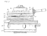
- the power tool illustrated in the drawings is of the angle drive type and comprises a housing 10, a rotation motor 11, an output shaft 12 arranged in a certain angle relative to the rotation axis of the motor 11, and an angle drive 13 coupling the output shaft 12 to the motor 11.
- the angle drive 13 comprises a pinion 16 connected to the motor 11 and a bevel gear 17 secured to the output shaft 12.
- the pinion 16 engages gear teeth on the upside of the bevel gear 17.
- the output shaft 12 is journalled relative to the housing 10 in two roller bearings 18,19 and carries at its forward end a combined ball-type balancing unit and a mounting device 20 for attaching a working implement (not shown) to the output shaft 12.
- a support disc 21 having a central splined opening 22 for receiving a matching clamping piece (not shown) for engaging the working implement.
- a stationary disc shaped wall element 24 forming a grease screen device.
- This wall element 24 is secured to the housing 10 by two screws 25 and is formed with a central opening 26 for receiving the output shaft 12 and a sleeve 27 with a hexagonal opening for the output shaft 12, and a lateral opening 28 for the pinion 16. See Fig. 4.
- the angle drive 13 comprises a gear chamber 30 having a forward end wall 31 supporting the forward output shaft bearing 18 and having a circular groove 32 concentrically disposed relative to the output shaft 12.
- the groove 32 has a rounded V-shape and forms a circular movement path for a grease relocating element 33.
- a coupling device 34 is mounted on the underside of the bevel gear 13 for activating and moving the grease relocating element 33 along the groove 32 at rotational movement of the output shaft 12 and the bevel gear 17.
- This coupling device 34 comprises a leaf spring element 35 having a free end portion 36 which is pre-formed to reach axially below the upper edge of the grease relocating element 33 (see Fig. 2) so as to positively engage by its free end portion 36 the grease relocating element 33 and move the latter along the groove 32 at reverse rotation of the output shaft 12.
- the leaf spring element 35 is secured to the underside of the bevel gear 17. See Fig. 4.
- the gear chamber 30 Before use of the power tool, the gear chamber 30 is filled up to a large extent, for instance to 70-90 % of its volume, with lubricating grease, and because of the grease screen forming wall element 24 a great part of the grease volume is prevented from getting into contact with the teeth of the bevel gear 17 and is, thereby, prevented from getting into the engagement zone between the pinion 16 and the bevel gear 17.
- the grease relocation element 33 could at least partly be formed of a magnetic material, whereas the leaf spring element 35 comprises a ferro-magnetic material. Thereby is accomplished a magnetic pulling force on the grease relocation element 35 each time the leaf spring element 35 passes the latter. Since the rotation speed of the output shaft 12 is high there is a high frequency of pulling force pulses, caused by friction or friction/magnetic action, acting on the grease relocation element 35 resulting in a successive advancement of the grease relocation element 35 in the groove 32 and, hence, a successive relocation of grease from underneath the bevel gear 17 to active lubricating areas.
Landscapes
- Engineering & Computer Science (AREA)
- Mechanical Engineering (AREA)
- Gear Transmission (AREA)
- General Details Of Gearings (AREA)
- Harvester Elements (AREA)
Applications Claiming Priority (2)
| Application Number | Priority Date | Filing Date | Title |
|---|---|---|---|
| SE0215246 | 2002-05-22 | ||
| SE0215246 | 2002-05-22 |
Publications (2)
| Publication Number | Publication Date |
|---|---|
| EP1364747A2 true EP1364747A2 (de) | 2003-11-26 |
| EP1364747A3 EP1364747A3 (de) | 2006-10-18 |
Family
ID=29398641
Family Applications (1)
| Application Number | Title | Priority Date | Filing Date |
|---|---|---|---|
| EP03445056A Withdrawn EP1364747A3 (de) | 2002-05-22 | 2003-05-14 | Tragbares Kraftwerkzeug mit drehendem Motor und fettgeschmiertem Winkelgetriebe |
Country Status (1)
| Country | Link |
|---|---|
| EP (1) | EP1364747A3 (de) |
Cited By (4)
| Publication number | Priority date | Publication date | Assignee | Title |
|---|---|---|---|---|
| GB2403171A (en) * | 2003-06-26 | 2004-12-29 | Bosch Gmbh Robert | Motor-driven hand grinding tool |
| RU2311282C2 (ru) * | 2004-11-05 | 2007-11-27 | Хитачи Коки Ко., Лтд. | Приводной инструмент с устройством для предотвращения утечки смазочного материала (варианты) |
| CN102371524A (zh) * | 2010-08-16 | 2012-03-14 | 株式会社牧田 | 手持工具 |
| RU2483864C2 (ru) * | 2009-12-25 | 2013-06-10 | Хитачи Коки Ко., Лтд. | Механизированный инструмент |
Family Cites Families (2)
| Publication number | Priority date | Publication date | Assignee | Title |
|---|---|---|---|---|
| DE3018774C2 (de) * | 1980-05-16 | 1982-11-18 | Licentia Patent-Verwaltungs-Gmbh, 6000 Frankfurt | Getriebegehäuse für Winkelschleifer mit einem einstufigen Kegelradgetriebe |
| SE509564C2 (sv) * | 1997-02-19 | 1999-02-08 | Atlas Copco Tools Ab | Motorverktyg med smord vinkelväxel |
-
2003
- 2003-05-14 EP EP03445056A patent/EP1364747A3/de not_active Withdrawn
Cited By (7)
| Publication number | Priority date | Publication date | Assignee | Title |
|---|---|---|---|---|
| GB2403171A (en) * | 2003-06-26 | 2004-12-29 | Bosch Gmbh Robert | Motor-driven hand grinding tool |
| GB2403171B (en) * | 2003-06-26 | 2006-03-29 | Bosch Gmbh Robert | Motor-driven hand grinding tool |
| RU2311282C2 (ru) * | 2004-11-05 | 2007-11-27 | Хитачи Коки Ко., Лтд. | Приводной инструмент с устройством для предотвращения утечки смазочного материала (варианты) |
| RU2483864C2 (ru) * | 2009-12-25 | 2013-06-10 | Хитачи Коки Ко., Лтд. | Механизированный инструмент |
| US8522890B2 (en) | 2009-12-25 | 2013-09-03 | Hitachi Koki Co., Ltd. | Power tool having lubricant leakage preventing structure |
| CN102371524A (zh) * | 2010-08-16 | 2012-03-14 | 株式会社牧田 | 手持工具 |
| CN102371524B (zh) * | 2010-08-16 | 2015-01-21 | 株式会社牧田 | 手持工具 |
Also Published As
| Publication number | Publication date |
|---|---|
| EP1364747A3 (de) | 2006-10-18 |
Similar Documents
| Publication | Publication Date | Title |
|---|---|---|
| US6871711B2 (en) | Portable power tool with grease lubricated angle gear drive | |
| US6712157B2 (en) | Portable power tool with rotation motor and grease lubricated angle drive | |
| JP4404387B2 (ja) | 潤滑型アングル駆動装置を備えた動力工具 | |
| KR100931641B1 (ko) | 폴리싱 머신용 기어툴 박스 구조 | |
| JP2009066753A (ja) | 遊星研磨機 | |
| US20110192621A1 (en) | Hammer and/or Hammer Drill Having Relubricating Device | |
| US8888642B2 (en) | Power tool | |
| EP2505309B1 (de) | Elektrisches Werkzeug | |
| AU2004222801B2 (en) | Trowel gearbox brake | |
| JP4942894B2 (ja) | 研削装置 | |
| JP2015058525A (ja) | 動力工具 | |
| CN119330196A (zh) | 一种矿用立井辅助提升装置 | |
| CN212706169U (zh) | 一种新型的大理石打磨装置 | |
| JPH09267274A (ja) | 電動工具の連動給油装置 | |
| CN206438548U (zh) | 一种平地机 | |
| KR200182417Y1 (ko) | 슬러지용 드럼스크린의 구동장치 | |
| EP1364747A3 (de) | Tragbares Kraftwerkzeug mit drehendem Motor und fettgeschmiertem Winkelgetriebe | |
| KR200160473Y1 (ko) | 베벨기어 | |
| JP3109972U (ja) | 研磨装置 | |
| CN115533220A (zh) | 一种齿轮轮齿定位抛光设备 | |
| GB2333981A (en) | A power tool attachment. | |
| JP2002308551A (ja) | エレベータの巻上機の漏油拭取り装置 | |
| HK1076299A (en) | Trowel gearbox brake |
Legal Events
| Date | Code | Title | Description |
|---|---|---|---|
| PUAI | Public reference made under article 153(3) epc to a published international application that has entered the european phase |
Free format text: ORIGINAL CODE: 0009012 |
|
| AK | Designated contracting states |
Kind code of ref document: A2 Designated state(s): AT BE BG CH CY CZ DE DK EE ES FI FR GB GR HU IE IT LI LU MC NL PT RO SE SI SK TR |
|
| AX | Request for extension of the european patent |
Extension state: AL LT LV MK |
|
| PUAL | Search report despatched |
Free format text: ORIGINAL CODE: 0009013 |
|
| AK | Designated contracting states |
Kind code of ref document: A3 Designated state(s): AT BE BG CH CY CZ DE DK EE ES FI FR GB GR HU IE IT LI LU MC NL PT RO SE SI SK TR |
|
| AX | Request for extension of the european patent |
Extension state: AL LT LV MK |
|
| 17P | Request for examination filed |
Effective date: 20070331 |
|
| 17Q | First examination report despatched |
Effective date: 20070502 |
|
| AKX | Designation fees paid |
Designated state(s): DE FR GB IT |
|
| STAA | Information on the status of an ep patent application or granted ep patent |
Free format text: STATUS: THE APPLICATION IS DEEMED TO BE WITHDRAWN |
|
| 18D | Application deemed to be withdrawn |
Effective date: 20070913 |