EP0861114B1 - Non-fouling, flow-through capacitor, system and method of separation - Google Patents
Non-fouling, flow-through capacitor, system and method of separation Download PDFInfo
- Publication number
- EP0861114B1 EP0861114B1 EP96936279A EP96936279A EP0861114B1 EP 0861114 B1 EP0861114 B1 EP 0861114B1 EP 96936279 A EP96936279 A EP 96936279A EP 96936279 A EP96936279 A EP 96936279A EP 0861114 B1 EP0861114 B1 EP 0861114B1
- Authority
- EP
- European Patent Office
- Prior art keywords
- capacitor
- electrodes
- flow
- daim
- flow path
- Prior art date
- Legal status (The legal status is an assumption and is not a legal conclusion. Google has not performed a legal analysis and makes no representation as to the accuracy of the status listed.)
- Expired - Lifetime
Links
- 239000003990 capacitor Substances 0.000 title claims abstract description 242
- 238000000034 method Methods 0.000 title claims abstract description 22
- 238000000926 separation method Methods 0.000 title claims abstract description 7
- 239000002699 waste material Substances 0.000 claims abstract description 35
- 239000012530 fluid Substances 0.000 claims abstract description 26
- 229920006395 saturated elastomer Polymers 0.000 claims abstract description 21
- 239000004020 conductor Substances 0.000 claims abstract description 19
- 239000000463 material Substances 0.000 claims description 50
- 125000006850 spacer group Chemical group 0.000 claims description 46
- OKTJSMMVPCPJKN-UHFFFAOYSA-N Carbon Chemical compound [C] OKTJSMMVPCPJKN-UHFFFAOYSA-N 0.000 claims description 43
- 239000000243 solution Substances 0.000 claims description 41
- 229910052751 metal Inorganic materials 0.000 claims description 31
- 239000002184 metal Substances 0.000 claims description 31
- 239000000047 product Substances 0.000 claims description 18
- 238000000746 purification Methods 0.000 claims description 15
- 239000012047 saturated solution Substances 0.000 claims description 11
- 239000002244 precipitate Substances 0.000 claims description 10
- 229910002804 graphite Inorganic materials 0.000 claims description 9
- 239000010439 graphite Substances 0.000 claims description 9
- BASFCYQUMIYNBI-UHFFFAOYSA-N platinum Chemical compound [Pt] BASFCYQUMIYNBI-UHFFFAOYSA-N 0.000 claims description 8
- 239000011888 foil Substances 0.000 claims description 7
- 239000007787 solid Substances 0.000 claims description 7
- 239000007788 liquid Substances 0.000 claims description 6
- 238000011084 recovery Methods 0.000 claims description 6
- 239000011230 binding agent Substances 0.000 claims description 5
- 239000000919 ceramic Substances 0.000 claims description 5
- 239000004964 aerogel Substances 0.000 claims description 4
- 230000015556 catabolic process Effects 0.000 claims description 4
- 229910052697 platinum Inorganic materials 0.000 claims description 4
- 230000008929 regeneration Effects 0.000 claims description 4
- 238000011069 regeneration method Methods 0.000 claims description 4
- 238000004891 communication Methods 0.000 claims description 3
- 239000007772 electrode material Substances 0.000 claims description 3
- VNWKTOKETHGBQD-UHFFFAOYSA-N methane Chemical class C VNWKTOKETHGBQD-UHFFFAOYSA-N 0.000 claims description 3
- 239000002245 particle Substances 0.000 claims description 3
- 238000001556 precipitation Methods 0.000 claims description 3
- 239000002131 composite material Substances 0.000 claims description 2
- 150000004767 nitrides Chemical class 0.000 claims description 2
- 229910000314 transition metal oxide Inorganic materials 0.000 claims description 2
- SGPGESCZOCHFCL-UHFFFAOYSA-N Tilisolol hydrochloride Chemical compound [Cl-].C1=CC=C2C(=O)N(C)C=C(OCC(O)C[NH2+]C(C)(C)C)C2=C1 SGPGESCZOCHFCL-UHFFFAOYSA-N 0.000 claims 16
- 238000010908 decantation Methods 0.000 claims 1
- 230000001172 regenerating effect Effects 0.000 claims 1
- 239000012527 feed solution Substances 0.000 description 15
- 238000013461 design Methods 0.000 description 14
- 239000007789 gas Substances 0.000 description 13
- FAPWRFPIFSIZLT-UHFFFAOYSA-M Sodium chloride Chemical compound [Na+].[Cl-] FAPWRFPIFSIZLT-UHFFFAOYSA-M 0.000 description 11
- OSGAYBCDTDRGGQ-UHFFFAOYSA-L calcium sulfate Chemical compound [Ca+2].[O-]S([O-])(=O)=O OSGAYBCDTDRGGQ-UHFFFAOYSA-L 0.000 description 11
- 230000006835 compression Effects 0.000 description 10
- 238000007906 compression Methods 0.000 description 10
- 239000013078 crystal Substances 0.000 description 10
- 238000002474 experimental method Methods 0.000 description 10
- 150000002739 metals Chemical class 0.000 description 9
- 230000008569 process Effects 0.000 description 9
- XLYOFNOQVPJJNP-UHFFFAOYSA-N water Substances O XLYOFNOQVPJJNP-UHFFFAOYSA-N 0.000 description 8
- RTAQQCXQSZGOHL-UHFFFAOYSA-N Titanium Chemical compound [Ti] RTAQQCXQSZGOHL-UHFFFAOYSA-N 0.000 description 7
- 239000004033 plastic Substances 0.000 description 7
- 229920003023 plastic Polymers 0.000 description 7
- 239000011780 sodium chloride Substances 0.000 description 7
- 229910052719 titanium Inorganic materials 0.000 description 7
- 239000010936 titanium Substances 0.000 description 7
- 229910052799 carbon Inorganic materials 0.000 description 6
- 239000002351 wastewater Substances 0.000 description 6
- 238000002425 crystallisation Methods 0.000 description 5
- 230000008025 crystallization Effects 0.000 description 5
- 230000008901 benefit Effects 0.000 description 4
- 239000000835 fiber Substances 0.000 description 4
- 238000001914 filtration Methods 0.000 description 4
- 229920006362 Teflon® Polymers 0.000 description 3
- 238000007599 discharging Methods 0.000 description 3
- 238000005868 electrolysis reaction Methods 0.000 description 3
- PCHJSUWPFVWCPO-UHFFFAOYSA-N gold Chemical compound [Au] PCHJSUWPFVWCPO-UHFFFAOYSA-N 0.000 description 3
- 229910052737 gold Inorganic materials 0.000 description 3
- 239000010931 gold Substances 0.000 description 3
- 238000004519 manufacturing process Methods 0.000 description 3
- 238000007789 sealing Methods 0.000 description 3
- VTYYLEPIZMXCLO-UHFFFAOYSA-L Calcium carbonate Chemical compound [Ca+2].[O-]C([O-])=O VTYYLEPIZMXCLO-UHFFFAOYSA-L 0.000 description 2
- HEDRZPFGACZZDS-UHFFFAOYSA-N Chloroform Chemical compound ClC(Cl)Cl HEDRZPFGACZZDS-UHFFFAOYSA-N 0.000 description 2
- 239000004593 Epoxy Substances 0.000 description 2
- XEEYBQQBJWHFJM-UHFFFAOYSA-N Iron Chemical compound [Fe] XEEYBQQBJWHFJM-UHFFFAOYSA-N 0.000 description 2
- 239000004809 Teflon Substances 0.000 description 2
- 238000010521 absorption reaction Methods 0.000 description 2
- 238000007792 addition Methods 0.000 description 2
- 230000015572 biosynthetic process Effects 0.000 description 2
- 238000001354 calcination Methods 0.000 description 2
- 230000005465 channeling Effects 0.000 description 2
- 239000012141 concentrate Substances 0.000 description 2
- 238000002242 deionisation method Methods 0.000 description 2
- 238000011033 desalting Methods 0.000 description 2
- 238000006073 displacement reaction Methods 0.000 description 2
- 238000005363 electrowinning Methods 0.000 description 2
- 239000006260 foam Substances 0.000 description 2
- 229910052736 halogen Inorganic materials 0.000 description 2
- 150000002367 halogens Chemical class 0.000 description 2
- 230000006872 improvement Effects 0.000 description 2
- 239000012212 insulator Substances 0.000 description 2
- 238000005342 ion exchange Methods 0.000 description 2
- 150000002500 ions Chemical class 0.000 description 2
- 244000005700 microbiome Species 0.000 description 2
- 239000012811 non-conductive material Substances 0.000 description 2
- 239000000843 powder Substances 0.000 description 2
- 238000011045 prefiltration Methods 0.000 description 2
- 239000012264 purified product Substances 0.000 description 2
- 238000012827 research and development Methods 0.000 description 2
- 239000000126 substance Substances 0.000 description 2
- 238000011144 upstream manufacturing Methods 0.000 description 2
- 238000012935 Averaging Methods 0.000 description 1
- XMWRBQBLMFGWIX-UHFFFAOYSA-N C60 fullerene Chemical class C12=C3C(C4=C56)=C7C8=C5C5=C9C%10=C6C6=C4C1=C1C4=C6C6=C%10C%10=C9C9=C%11C5=C8C5=C8C7=C3C3=C7C2=C1C1=C2C4=C6C4=C%10C6=C9C9=C%11C5=C5C8=C3C3=C7C1=C1C2=C4C6=C2C9=C5C3=C12 XMWRBQBLMFGWIX-UHFFFAOYSA-N 0.000 description 1
- 239000004966 Carbon aerogel Substances 0.000 description 1
- 239000004215 Carbon black (E152) Substances 0.000 description 1
- JOYRKODLDBILNP-UHFFFAOYSA-N Ethyl urethane Chemical compound CCOC(N)=O JOYRKODLDBILNP-UHFFFAOYSA-N 0.000 description 1
- 239000002253 acid Substances 0.000 description 1
- 150000007513 acids Chemical class 0.000 description 1
- 230000009471 action Effects 0.000 description 1
- 230000004913 activation Effects 0.000 description 1
- 239000000654 additive Substances 0.000 description 1
- 230000000996 additive effect Effects 0.000 description 1
- WYTGDNHDOZPMIW-RCBQFDQVSA-N alstonine Natural products C1=CC2=C3C=CC=CC3=NC2=C2N1C[C@H]1[C@H](C)OC=C(C(=O)OC)[C@H]1C2 WYTGDNHDOZPMIW-RCBQFDQVSA-N 0.000 description 1
- 229910052782 aluminium Inorganic materials 0.000 description 1
- XAGFODPZIPBFFR-UHFFFAOYSA-N aluminium Chemical compound [Al] XAGFODPZIPBFFR-UHFFFAOYSA-N 0.000 description 1
- 229910052925 anhydrite Inorganic materials 0.000 description 1
- 239000011324 bead Substances 0.000 description 1
- 230000002457 bidirectional effect Effects 0.000 description 1
- 230000000903 blocking effect Effects 0.000 description 1
- 229910000019 calcium carbonate Inorganic materials 0.000 description 1
- 239000003575 carbonaceous material Substances 0.000 description 1
- 230000003197 catalytic effect Effects 0.000 description 1
- 230000008859 change Effects 0.000 description 1
- 238000006243 chemical reaction Methods 0.000 description 1
- 150000008280 chlorinated hydrocarbons Chemical class 0.000 description 1
- 239000011248 coating agent Substances 0.000 description 1
- 238000000576 coating method Methods 0.000 description 1
- 239000000571 coke Substances 0.000 description 1
- 239000000084 colloidal system Substances 0.000 description 1
- 229920001940 conductive polymer Polymers 0.000 description 1
- 238000010276 construction Methods 0.000 description 1
- 239000000356 contaminant Substances 0.000 description 1
- 238000011109 contamination Methods 0.000 description 1
- 238000001816 cooling Methods 0.000 description 1
- 230000001186 cumulative effect Effects 0.000 description 1
- 238000005520 cutting process Methods 0.000 description 1
- 230000002939 deleterious effect Effects 0.000 description 1
- 230000006866 deterioration Effects 0.000 description 1
- 238000010586 diagram Methods 0.000 description 1
- 238000010790 dilution Methods 0.000 description 1
- 239000012895 dilution Substances 0.000 description 1
- 239000012153 distilled water Substances 0.000 description 1
- 230000000694 effects Effects 0.000 description 1
- 238000000909 electrodialysis Methods 0.000 description 1
- 238000009713 electroplating Methods 0.000 description 1
- 238000005516 engineering process Methods 0.000 description 1
- 239000002657 fibrous material Substances 0.000 description 1
- 239000010408 film Substances 0.000 description 1
- 229920002313 fluoropolymer Polymers 0.000 description 1
- 229910003472 fullerene Inorganic materials 0.000 description 1
- 239000003292 glue Substances 0.000 description 1
- 231100001261 hazardous Toxicity 0.000 description 1
- 238000010438 heat treatment Methods 0.000 description 1
- 229930195733 hydrocarbon Natural products 0.000 description 1
- 150000002430 hydrocarbons Chemical class 0.000 description 1
- XLYOFNOQVPJJNP-UHFFFAOYSA-M hydroxide Chemical compound [OH-] XLYOFNOQVPJJNP-UHFFFAOYSA-M 0.000 description 1
- 239000004615 ingredient Substances 0.000 description 1
- 229910052742 iron Inorganic materials 0.000 description 1
- 235000014413 iron hydroxide Nutrition 0.000 description 1
- NCNCGGDMXMBVIA-UHFFFAOYSA-L iron(ii) hydroxide Chemical compound [OH-].[OH-].[Fe+2] NCNCGGDMXMBVIA-UHFFFAOYSA-L 0.000 description 1
- 150000002605 large molecules Chemical class 0.000 description 1
- 239000006193 liquid solution Substances 0.000 description 1
- 239000010808 liquid waste Substances 0.000 description 1
- 229920002521 macromolecule Polymers 0.000 description 1
- 238000001471 micro-filtration Methods 0.000 description 1
- 230000002906 microbiologic effect Effects 0.000 description 1
- 238000002156 mixing Methods 0.000 description 1
- 239000000203 mixture Substances 0.000 description 1
- 238000012986 modification Methods 0.000 description 1
- 230000004048 modification Effects 0.000 description 1
- 239000002991 molded plastic Substances 0.000 description 1
- 239000002071 nanotube Substances 0.000 description 1
- 229910052758 niobium Inorganic materials 0.000 description 1
- 239000010955 niobium Substances 0.000 description 1
- GUCVJGMIXFAOAE-UHFFFAOYSA-N niobium atom Chemical compound [Nb] GUCVJGMIXFAOAE-UHFFFAOYSA-N 0.000 description 1
- 238000010899 nucleation Methods 0.000 description 1
- 230000003647 oxidation Effects 0.000 description 1
- 238000007254 oxidation reaction Methods 0.000 description 1
- -1 oxidizers Substances 0.000 description 1
- ISWSIDIOOBJBQZ-UHFFFAOYSA-N phenol group Chemical group C1(=CC=CC=C1)O ISWSIDIOOBJBQZ-UHFFFAOYSA-N 0.000 description 1
- 238000007747 plating Methods 0.000 description 1
- 150000003057 platinum Chemical class 0.000 description 1
- 238000005498 polishing Methods 0.000 description 1
- 239000004800 polyvinyl chloride Substances 0.000 description 1
- 239000011148 porous material Substances 0.000 description 1
- 238000002360 preparation method Methods 0.000 description 1
- 238000005086 pumping Methods 0.000 description 1
- 239000011347 resin Substances 0.000 description 1
- 229920005989 resin Polymers 0.000 description 1
- 238000001223 reverse osmosis Methods 0.000 description 1
- 238000009991 scouring Methods 0.000 description 1
- 238000007650 screen-printing Methods 0.000 description 1
- 238000004904 shortening Methods 0.000 description 1
- 150000003384 small molecules Chemical class 0.000 description 1
- 239000002910 solid waste Substances 0.000 description 1
- 239000002904 solvent Substances 0.000 description 1
- 229910001220 stainless steel Inorganic materials 0.000 description 1
- 239000010935 stainless steel Substances 0.000 description 1
- 238000003860 storage Methods 0.000 description 1
- 239000000758 substrate Substances 0.000 description 1
- 229910052715 tantalum Inorganic materials 0.000 description 1
- GUVRBAGPIYLISA-UHFFFAOYSA-N tantalum atom Chemical compound [Ta] GUVRBAGPIYLISA-UHFFFAOYSA-N 0.000 description 1
- 238000012360 testing method Methods 0.000 description 1
- 229920002803 thermoplastic polyurethane Polymers 0.000 description 1
- 239000010409 thin film Substances 0.000 description 1
- 230000001960 triggered effect Effects 0.000 description 1
- 229910021642 ultra pure water Inorganic materials 0.000 description 1
- 238000000108 ultra-filtration Methods 0.000 description 1
- 239000012498 ultrapure water Substances 0.000 description 1
- 238000005406 washing Methods 0.000 description 1
- 239000003643 water by type Substances 0.000 description 1
- 239000002349 well water Substances 0.000 description 1
- 235000020681 well water Nutrition 0.000 description 1
Images


Classifications
-
- C—CHEMISTRY; METALLURGY
- C02—TREATMENT OF WATER, WASTE WATER, SEWAGE, OR SLUDGE
- C02F—TREATMENT OF WATER, WASTE WATER, SEWAGE, OR SLUDGE
- C02F1/00—Treatment of water, waste water, or sewage
- C02F1/46—Treatment of water, waste water, or sewage by electrochemical methods
- C02F1/469—Treatment of water, waste water, or sewage by electrochemical methods by electrochemical separation, e.g. by electro-osmosis, electrodialysis, electrophoresis
- C02F1/4691—Capacitive deionisation
-
- B—PERFORMING OPERATIONS; TRANSPORTING
- B01—PHYSICAL OR CHEMICAL PROCESSES OR APPARATUS IN GENERAL
- B01D—SEPARATION
- B01D15/00—Separating processes involving the treatment of liquids with solid sorbents; Apparatus therefor
-
- B—PERFORMING OPERATIONS; TRANSPORTING
- B01—PHYSICAL OR CHEMICAL PROCESSES OR APPARATUS IN GENERAL
- B01J—CHEMICAL OR PHYSICAL PROCESSES, e.g. CATALYSIS OR COLLOID CHEMISTRY; THEIR RELEVANT APPARATUS
- B01J47/00—Ion-exchange processes in general; Apparatus therefor
- B01J47/02—Column or bed processes
- B01J47/06—Column or bed processes during which the ion-exchange material is subjected to a physical treatment, e.g. heat, electric current, irradiation or vibration
- B01J47/08—Column or bed processes during which the ion-exchange material is subjected to a physical treatment, e.g. heat, electric current, irradiation or vibration subjected to a direct electric current
-
- G—PHYSICS
- G01—MEASURING; TESTING
- G01N—INVESTIGATING OR ANALYSING MATERIALS BY DETERMINING THEIR CHEMICAL OR PHYSICAL PROPERTIES
- G01N30/00—Investigating or analysing materials by separation into components using adsorption, absorption or similar phenomena or using ion-exchange, e.g. chromatography or field flow fractionation
- G01N30/02—Column chromatography
- G01N30/50—Conditioning of the sorbent material or stationary liquid
-
- G—PHYSICS
- G01—MEASURING; TESTING
- G01N—INVESTIGATING OR ANALYSING MATERIALS BY DETERMINING THEIR CHEMICAL OR PHYSICAL PROPERTIES
- G01N30/00—Investigating or analysing materials by separation into components using adsorption, absorption or similar phenomena or using ion-exchange, e.g. chromatography or field flow fractionation
- G01N30/02—Column chromatography
- G01N30/60—Construction of the column
- G01N30/6052—Construction of the column body
- G01N30/6069—Construction of the column body with compartments or bed substructure
-
- G—PHYSICS
- G01—MEASURING; TESTING
- G01N—INVESTIGATING OR ANALYSING MATERIALS BY DETERMINING THEIR CHEMICAL OR PHYSICAL PROPERTIES
- G01N30/00—Investigating or analysing materials by separation into components using adsorption, absorption or similar phenomena or using ion-exchange, e.g. chromatography or field flow fractionation
- G01N30/96—Investigating or analysing materials by separation into components using adsorption, absorption or similar phenomena or using ion-exchange, e.g. chromatography or field flow fractionation using ion-exchange
-
- C—CHEMISTRY; METALLURGY
- C02—TREATMENT OF WATER, WASTE WATER, SEWAGE, OR SLUDGE
- C02F—TREATMENT OF WATER, WASTE WATER, SEWAGE, OR SLUDGE
- C02F2301/00—General aspects of water treatment
- C02F2301/02—Fluid flow conditions
- C02F2301/024—Turbulent
-
- G—PHYSICS
- G01—MEASURING; TESTING
- G01N—INVESTIGATING OR ANALYSING MATERIALS BY DETERMINING THEIR CHEMICAL OR PHYSICAL PROPERTIES
- G01N30/00—Investigating or analysing materials by separation into components using adsorption, absorption or similar phenomena or using ion-exchange, e.g. chromatography or field flow fractionation
- G01N30/02—Column chromatography
- G01N2030/022—Column chromatography characterised by the kind of separation mechanism
- G01N2030/027—Liquid chromatography
-
- G—PHYSICS
- G01—MEASURING; TESTING
- G01N—INVESTIGATING OR ANALYSING MATERIALS BY DETERMINING THEIR CHEMICAL OR PHYSICAL PROPERTIES
- G01N30/00—Investigating or analysing materials by separation into components using adsorption, absorption or similar phenomena or using ion-exchange, e.g. chromatography or field flow fractionation
- G01N30/96—Investigating or analysing materials by separation into components using adsorption, absorption or similar phenomena or using ion-exchange, e.g. chromatography or field flow fractionation using ion-exchange
- G01N2030/965—Investigating or analysing materials by separation into components using adsorption, absorption or similar phenomena or using ion-exchange, e.g. chromatography or field flow fractionation using ion-exchange suppressor columns
-
- G—PHYSICS
- G01—MEASURING; TESTING
- G01N—INVESTIGATING OR ANALYSING MATERIALS BY DETERMINING THEIR CHEMICAL OR PHYSICAL PROPERTIES
- G01N30/00—Investigating or analysing materials by separation into components using adsorption, absorption or similar phenomena or using ion-exchange, e.g. chromatography or field flow fractionation
- G01N30/02—Column chromatography
- G01N30/26—Conditioning of the fluid carrier; Flow patterns
- G01N30/38—Flow patterns
- G01N30/46—Flow patterns using more than one column
- G01N30/461—Flow patterns using more than one column with serial coupling of separation columns
-
- G—PHYSICS
- G01—MEASURING; TESTING
- G01N—INVESTIGATING OR ANALYSING MATERIALS BY DETERMINING THEIR CHEMICAL OR PHYSICAL PROPERTIES
- G01N30/00—Investigating or analysing materials by separation into components using adsorption, absorption or similar phenomena or using ion-exchange, e.g. chromatography or field flow fractionation
- G01N30/02—Column chromatography
- G01N30/60—Construction of the column
- G01N30/6034—Construction of the column joining multiple columns
- G01N30/6043—Construction of the column joining multiple columns in parallel
-
- G—PHYSICS
- G01—MEASURING; TESTING
- G01N—INVESTIGATING OR ANALYSING MATERIALS BY DETERMINING THEIR CHEMICAL OR PHYSICAL PROPERTIES
- G01N30/00—Investigating or analysing materials by separation into components using adsorption, absorption or similar phenomena or using ion-exchange, e.g. chromatography or field flow fractionation
- G01N30/02—Column chromatography
- G01N30/60—Construction of the column
- G01N30/6095—Micromachined or nanomachined, e.g. micro- or nanosize
Definitions
- a flow-through capacitor can be constructed with multiple, generally parallel open flow paths.
- the capacitor of the present invention utilizes this design and method to provide a fouling resistant flow-through capacitor with a compact and easy to manufacture construction.
- Flow-through capacitors of the prior art function by concentration of solutes in the feed stream into a concentrated waste stream. This has two serious disadvantages.
- the first disadvantage is that the method of waste recovery into a concentrated waste stream generates waste water. Waste water of any kind is often a significant process. cost.
- U.S. Patent 5,425,858 by Joseph Farmer describes a flow-through capacitor whose spacer layers define an open channel with a long serpentine flow path.
- the flow path is not also directly open to the outside, but is circumscribed by a gasket and forced to flows between holes in the successive multiple structural layers, and thence through an outlet.
- Serpentine channels provide bends where crystal and precipitates can settle, thereby blocking the flow path. Fluid flow-through holes in many successive structural layers further constrict the flow and offer many places for fouling to occur and multiple opportunity for solids to plug the flow path.
- a short flow path is preferable in order to flush the saturated waste out of the capacitor before the kinetic process of crystallization forms precipitates and causes fouling or crystals.
- the long flow path that a serpentine channel provides makes it difficult to flush the capacitor before crystallization occurs. Once solids do form inside the capacitor, it is that much more difficult to flush them through a long enclosed flow path.
- the Farmer patent suffers from other disadvantages.
- the plate frame design depends upon multiple sealing gaskets. This provides multiple opportunities for leaks, and therefore requires hardware such as heavy, structural, metal end plates and threaded rods to tightly compress the stack.
- the structural, metallic end plates are conductive, and therefore, in addition to the gasket spacers, require an extra non-conductive insulator layer between the end electrodes and the end plate.
- the electrodes in the Farmer device consist of a titanium metal sheet sandwiched between two high surface are layers. To effect leak tight seals, the titanium metal sheets also have to be thick and structural, rather than the thin metal foils described in the Andelman patents. This adds to the cost and bulk of the system.
- titanium is not the best choice, as titanium is a valve metal, and forms a non-conductive oxide coating under conditions which may occur during use of the flow-through capacitor.
- the Farmer device uses a conductive epoxy rather than a compression contact between the titanium sheets and the high surface area materials. This unnecessarily increases resistance of the electrical contact. The use of glue to form a contact would also shorten the lifetime of the capacitor device due to eventual deterioration of the bond.
- Such a capacitor would be resistant to fouling. It would furthermore be desirable that such a capacitor reduce or even eliminate the waste water entirely. Finally, it would be desirable for such a capacitor to be easy to manufacture, and not have any unnecessary parts that increase cost, or limit the usefulness of the capacitor.
- the invention relates to a foul-resistant capacitor, system and method, and in particular, a capacitor, system and method for the separation of solutes or fluids which tend to clog or foul the capacitor.
- the invention comprises a flow-through capacitor having at least one anode and at least one cathode adapted to be connected to a power supply, the capacitor arranged and constructed for use in the separation, electrical purification, concentration, recovery or electrochemical treatment or breakdown of solutes or fluids, particularly solutes and fluids which are saturated or substantially saturated and which tend to foul the capacitor.
- the capacitor includes one or more monolithic, spaced apart pairs of anode and cathode electrodes incorporating a high surface area electrically conductive material and having a non-conductive spacer between the anode and cathode electrodes, characterized by an open flow path between the electrodes to permit the unobstructed flow of the fluid across the electrode surface, wherein the width of the flow path is less than 0.127 cm (50 mils) and wherein the open flow path has at least one dimension open to an exterior of the capacitor.
- the fouling-resistant, flow-through capacitor of the invention is able to treat saturated solutions.
- the flow-through capacitor takes into account that subsequent formation of fouling precipitates and crystals from a super-saturated solution is a kinetic process. Therefore, the flow-through capacitor design is configured such that the fluid flow path through the capacitor is short, generally straight and open. To allow optimal and unobstructed wash out of solids in the capacitor, it is also desirable for this flow path to be open directly to the outside of the capacitor and not have to pass directly through multiple holes or constrictions. Therefore, the open channels created by the spaced apart electrodes communicate directly with the outside surface of the capacitor. These channels are not circumscribed by a gasket, but preferably have one dimension completely free of obstruction to flow. Where possible, it is also preferable to make the flow path wide.
- a short, straight, open flow path, communicating directly with the outside surface of the capacitor has many advantages.
- a waste or feed solution including a saturated or a super-saturated solution, can be flushed out of the capacitor before the process of crystallization takes place. Should the waste or feed solution be left in the capacitor long enough for crystals to form inside the capacitor, such fouling crystals can be flushed out through the straight and open flow path. Turbidity or particles present in the feed can also be flushed out through the capacitor without fouling the system. Because the flow path is directly open to the outside, it is also possible to clean mechanically between the electrodes without disassembling the capacitor.
- the generally straight, short, open, wide flow path of the solute can be accomplished by replacing the porous spacer of the capacitors with multiple thin stripe, shims, washers or open netting (such as sold by Malle Plastics Inc. of Austin, Texas under the tradename Naltex), preferably including bidirectional filtration netting.
- Spacers may be any inert, non-conductive material, such as, but not limited to: fluorocarbon polymers, like Teflon®; ceramic beads; washer shapes; individual shims; or plastic netting, preferably biplanar filtration netting.
- the spacers may include microprotrusions screen printed onto the electrodes as disclosed in U.S.
- Patent 5,384,685 "Screen printing of microprotrusions for use as a space separator in an electrical storage device", to Tong et al, hereby incorporated by reference.
- any material in any shape which is thin in cross section and electrically non-conductive can be used to space apart the anode and cathode electrodes of the capacitor.
- Spacers need not be separate layers, but may also be built into internal or external supports.
- an internal supporting rod may contain risers or notches which are used to space apart the electrodes. The same thing may be accomplished with an external support or scaffold.
- the space between the electrodes should be as narrow as possible. Too narrow a flow path, however, increases the possibility of accidental shorting between the layers and enhances fouling.
- the optimal spacer thickness in one embodiment is less than about 0.127 cm (50mils), for example, between about 0.0127 cm (5mils) and 0.0508 cm (20mils).
- the spacer material need not be elastic or rubbery in nature.
- the spacer material serves only to space the electrodes apart and not to form a seal in the capacitor. Therefore, only enough compression is required to hold the layers together, or to form an electrical contact between the conductive high surface area layers and any optional conductive backing layers to the electrodes. Either no end caps are required or less mechanically strong, non-conductive materials can be used, such as plastic materials. Therefore, the heavy structural metal end plates and connecting threaded rods can be eliminated. As a consequence, the insulator layer of the former or prior art devices disposed between the end plate and the end electrodes may be eliminated.
- the flow path should also be short, and directly communicate with the outside surface. Spacers may also and simultaneously function to provide internal support for a compression contract between high surface area layer conductive backing layers. Where possible, a wide flow path is also desirable.
- the present invention in the preferred embodiment employs multiple straight, parallel flow paths through the spaced apart electrode layers more preferably, there are at least as many flow paths as there are spacers between the electrodes.
- the width of the flow path should be short and, like the thickness, less than about 0.127 cm (50 mils), and more typically, about 0.0127 cm to 0.0508 cm - 0.0762 cm (5 to 20-30 mils).
- the length of the flow path should also be short and should usually be the lesser dimension of the X-Y-Z dimensions of the capacitor, and no longer in length than the length or height of the electrode for example, less than about 30.48 cm (12 inches), for example, about 15.24 cm (six inches) or less.
- the electrodes may be made from any high surface area material. Where it is desirable to enhance the conductivity of the high surface area conductive material, a further conductive backing layer may be employed in direct contact with the electrodes. Where the intrinsic electrical conductivity of the electrodes is sufficient, this conductive backing layer may be eliminated. It is desirable to keep internal resistance capacitor as low as possible. Internal resistance sets a limit on charging time of the capacitor, which in turn directly limits the ultimate mass and fluid flow rates that it is possible to purify solutes and solutions. An internal resistance of less than about four ohms, e.g. one ohm, is preferred.
- the electrodes may be made out of any monolithic high surface area conductive materials, in at least one anode/cathode pair. Where the high surface area material is conductive, but not optimally conductive, an electrical conductive backing may be employed.
- High surface area conductive materials suitable for use in the present invention include, but are not limited to: activated carbon; activated carbon treated with a halogen; carbon foams; carbon aerogel and aerogel composite materials; nanotubes; conductive polymers, especially in porous or network form; polymerized fullerenes; or any high surface area conductive material may be used.
- Conductive ceramics may also be used, either by themselves or impregnated onto high surface area substrates, including various forms of carbon such as fiber, foam, powder or aerogel.
- absorbing any electrically actuated small or large molecule onto the conductive high surface area material that improves the capacitance will improve the function of the capacitor.
- Another preferred high surface area conductive material is conductive transition metal oxides, nitrides, or borides prepared using sol/gel technique. Powdered high surface area materials may be sintered into monolithic electrodes or bound together with binder materials. Monolithic high surface area material can be activated carbon sintered together with a binder and doped with a metal.
- Intrinsically conductive electrodes where no backing layer is required would include high surface area preparations of graphitic carbon, high surface area expanded metals, metal fibers, or metal meshes.
- high surface area expanded metals For example, titanium fibers coated with high surface area platinum series black are known and are marketed as electrode materials.
- Other examples include platinum coated niobium and foamed metals.
- High surface area carbon materials may be mixed with metal or graphitic fibers or meshes and formed into monolithic units.
- Another type of electrode includes a non-conductive high surface area material in intimate contact with a conductive backing.
- a non-conductive high surface area material in intimate contact with a conductive backing.
- An example of this would be an oxide layer on etched tantalum or aluminum, oxidized conductive ceramics, or thin films deposited on any high surface area conductive material.
- a capacitor with this material has the advantage that the solution is protected from direct contact with a conductive material. Therefore, the capacitor can be operated under much higher voltages, up to 50 volts or more, as opposed to a naked high surface area conductive material, which is limited by the breakdown voltage of the solution.
- Figs. 1 and 2 show capacitors with washer-style electrodes about a central tube or rod. The flow path is between the washer electrodes and out through the central tube.
- Fig. 6 shows a short, fat spiral wound arrangement, where the flow path is between the electrodes in the longitudinal direction, parallel the central axis.
- the spiral wound capacitor may contain a structural central rod or tube.
- the electrodes may also be fashioned as interlocking or overlapping pleats in various flat or cylindrical geometries.
- Figs. 7A and 7B show a crescent pleat design where the electrodes are placed as overlapping pleats about a central tube, where the flow path is between the electrodes in the horizontal direction, and thence longitudinally out through the central tube, which contains holes along its length.
- Fig. 9 shows a flat capacitor made up of rectangular electrodes, with the flow path across the short dimension of the electrodes, between the electrodes. Alternatively, these multiple electrodes could be replaced by two or more interlocking pleated electrodes.
- the capacitor In addition to shortening the flow path, the capacitor should be operated so that polarity is reversed in every charge cycle, so that no net buildup will occur on the electrodes. Since the electrodes are electrically active, reversing polarity makes the former anode into a cathode and the former cathode into an anode. Precipitates and deposits which may have favorably formed on one of either the anode or cathode will therefore be driven off, thereby further reducing fouling of the capacitor. To further minimize fouling, the flow-through capacitor should be backwashed by reversing the flow, for example, every charge or discharge cycle. This also helps avoid buildup of solids because there is no net flow in any one direction. It may also be desirable to continuously or occasionally operate the capacitor at slight overvoltage. This causes a small of electrolysis which keeps the electrodes clean of microbes and foulants.
- the combination of short, straight, open flow path, polarity reversal and optional backwash enables the flow-through capacitor of the invention to purify even saturated solutions, and to concentrate such solutions all the way until crystallization occurs.
- This phenomenon generates a further advantage.
- the fouling resistance offered by the straight, open flow path of the capacitor of the invention allows the flow-through capacitor to be operated to generate a solid instead of a liquid waste.
- the flow-through capacitor is connected to a tank of saturated waste. During the regeneration cycle, the capacitor is filled with saturated solution from the waste tank. The capacitor is discharged into this saturated water, which is then flushed back into the waste tank. Precipitation occurs because, upon desorbing its ions, the capacitor super-saturates this saturated waste water.
- the straight and open flow path of the present design allows the precipitates to be flushed directly out of the capacitor for recovery or removal.
- the precipitate settles into the bottom of the waste tank, which can be collected separately by decanting or filtration. This process can be repeated indefinitely.
- the waste solution may alternatively, instead of forming a precipitate, become super-saturated. In this case, the solution can be triggered to precipitate by heating, cooling, vibration, seeding with small crystal, adjusting pH, or other precipitation methods.
- a further disadvantage of prior art that is overcome by the present capacitor design is the dilution of product solution with dead volume of the capacitor.
- the capacitor described in U.S. Patent 5,425,858 has a dead volume of 250 mls. This dead volume is deleterious, because waste solution left over after discharge needs to be flushed out with fresh feed solution, therefore generating additional waste water. If this waste solution is not adequately flushed out, then, upon charging the capacitor during a purification cycle, the capacitor repurifies in an inefficient manner the concentrated waste still present in the capacitor. This inefficiency gets worse with increasing feed solution concentration, due to the fact that the capacitor in this situation gets saturated faster, and needs to be regenerated more often. The more often the capacitor is regenerated, the greater the opportunity for contamination of product solution with the dead volume.
- the flow-through capacitor of the present invention minimizes the dead volume problem, such as by connecting the capacitor to a source of pressurized gas, such as air, N 2 or other gases chosen not to react with or contaminate the product.
- a source of pressurized gas such as air, N 2 or other gases chosen not to react with or contaminate the product.
- the short and straight flow channels are optimal for allowing the solution inside to be displace with a gas.
- liquid contained in serpentine channels of a prior art capacitor would be more difficult to displace due to the tendency to form protected pockets.
- This displacement of dead volume with a gas or fluid is also difficult with the porous spacer design of the other patents, due to channeling. Any preference or unevenness in manufacture would cause channeling of gas or liquid fluids, and uneven displacement of the waste liquid with the gas. None of the prior art utilizes a gas to displace the dead volume.
- Two or more foul-resistant, short flow path capacitors can be operated continuously in a system, one charging while the other discharges.
- a discharging capacitor can be used to charge other capacitors.
- Single charged capacitors can only be used to charge another capacitor until their voltages equalize. Among two capacitors of equal size, this wastes half of the energy in the discharging capacitor.
- two or more of these half charged capacitors can be connected in series.
- the series voltage of capacitors connected in series is additive. Connection of capacitors in series allows continued use of the depleted capacitors energy to charge other capacitors.
- U. S. Patent 5,475,858 describes the use of single capacitors for energy recovery to recharge other capacitors; however connection in series makes it possible to recoup energy from the remaining half of the unutilized energy.
- Multiple capacitors in a system allow for alternating and continuous, simultaneous charge and discharge in order to provide uninterrupted product flow. Uninterrupted flow can also be achieved with a single flow-through capacitor by including a hold-up tank downstream that is used to average the flow between charge or discharge cycles. This allows for a simpler single capacitor system design.
- a further improvement of the flow-through capacitor involves doping the carbon electrodes with a metal, such as platinum, titanium, or other metals with catalytic properties. This allows the capacitor to more easily electrochemically destroy chlorinated hydrocarbons, chloroform and other hazardous organic molecules.
- the metals overcome the activation energy of reactions such as removing a halogen from a hydrocarbon, or breaking down an organic molecule.
- a preferred way to control the flow-through capacitor is to use the capacitor as its own sensor. In this system, both current and time are recorded, with the current measured through a shunt resistor.
- a computer integrates current versus time to calculate total charge that has been transferred into the capacitor. After a preset value of total charge has passed into the capacitor, a controller automatically activates the regeneration cycle, which involves first disconnecting the power supply, waiting a short time to safeguard the electronics, shorting the capacitor through a load, and actuating the appropriate valves and pumps that select and isolate the waste stream from the product stream.
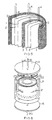
- Fig. 1 shows a stacked washer flow-through capacitor, whose high surface area electrodes contain a backing layer.
- the electrodes consist in combination of electrically conductive high surface area material 1 and conductive backing 2.
- the end electrodes may be either single or double sided, whereas the intermediate electrodes are preferably double sided.
- the electrical contact between the high surface area layer 1 and the conductive backing layer 2 is preferably a compression contact, which is afforded by the screw on end caps 7 tightened around central rod or tube 5 around threads 6.
- the electrodes are present in even numbers to form at least one anode/cathode pair.
- the anode and cathodes so formed are separated by spacers 3. Integral leads 4 extend from conductive backing (2).
- leads may be joined together to connect separately, in parallel alignment to themselves, the alternate anode and cathode layers, or they may be gathered together to accomplish the same purpose and to form an electrical lead.
- Fluid flow is between the spaced apart electrodes and through the holes 9 and then out through the central tube 5.
- a ribbed rod may be substituted with fluid flow alongside the longitudinal ribs. Washer means 8 are provided to allow the cartridge to form a leak proof seal inside cartridge holders (see Fig. 4).
- Fig. 2 shows a washer-style flow-through capacitor with high surface area electrodes that are sufficiently conductive that no conductive backing is required. Integral leads 4 are attached to high surface area conductive material 1, which forms alternating anode cathode pairs separated by spacers 3.
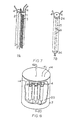
- Figs. 3A-G show various styles of spacers that may be used in the flow-through capacitor of the present invention.
- the spacer may be in the form of an open net (Fig. 3A), such as manufactured filtration netting (e.g. Naltex). This netting may be symmetrical or non-symmetrical. Biplanar netting is preferred, because this sort of weave does not obstruct the flow path along the surface of the netting.
- the spacer material may also consist of protrusions, such as the screen printed microprotrusions of U. S. Patent 5,384,685 by Robert Tong et al.
- One preferred embodiment would be washer-style circular spacers, such as the star-shaped spacer (Fig. 3C). Another preferred embodiment (Fig.
- 3D would include individual shims, small rods, or threads, laid out between the anode/cathode layers to space these apart. Also depicted are spacers that are integrally formed from a central or external support, such as spaced notches in a central tube, or an external scaffold arrangement with spaced risers whereupon the electrodes are placed (Fig. 3E).
- the multiple parallel flow paths allow the addition of extra length to the individual flow paths without a problem with pressure drop due to excessive elongation.
- Flow paths that are short and straight in the strictest sense are an ideal that is preferred in most cases.
- An exception would be, for example, a gel-like foulant such as iron hydroxide formation, which would require a turbulent or very fast flow to break up.
- the most common example requiring the shortest, straightest and widest flow path possible would be rapidly crystallizing solutions.
- the flow-through capacitor of the invention enables optimum function of the process due to the utilization of the shorter, multiple flow path design as desired.
- Figs. 4A-B show the assembled flow-through capacitor of Figs. 1 or 2.
- the spacers create open space 10 between the high surface area conductive material 1.
- the washer shaped electrodes are assembled around central tube 5 and held in place by end caps 7.
- Leads 4 interconnect the alternate electrodes to form anode/cathode pairs.
- Anodes are connected to anodes and cathodes connected to cathodes, in parallel arrangement.
- Fig. 4B depicts the assembled flow-through capacitor of Fig. 4A in a cartridge holder 17.
- the cartridge holder is fitted with a screw-on lid 15 with threads 16.
- the lid contains two graphite rods 12. When lid 15 is screwed down upon cartridge holder 17, graphite rods come into electrical contract with the two concentric electrical contacts 18.
- the graphite rods 12 are attached to a spring 11 which provides a controlled tension and downward force that makes an electrical contact with concentric conductor 18.
- Metal caps 13 form a compression electrical contract with graphite rods 12 to connect electrically to wire leads 14, for connection to a DC power supply.
- the lid 15 is provided with an inlet 19, and the cartridge holder 17 is provided with an outlet 20. Washer means 8 seal against both the lid and the cartridge holder to form leak tight seals. The flow path is through the inlet, then between the spaced apart electrode layers, then out through the outlet.
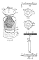
- Fig. 5 depicts a spiral wound capacitor of the present invention utilizing conductive high surface area material 1, optional conductive backing 2, and spacer material 3 in a netting or open mesh form.
- Electric leads 4 extend from the electrodes formed from material 1 or the optional conductive backing 2.
- the capacitor may optionally be wound around a structural central rod 5. This capacitor is preferably made short and fat, with the width wider than the length of the capacitor as measured down the central axis.
- Fig. 6 depicts the short, fat capacitor of Fig. 5 in a cartridge holder or piece of pipe 17.
- the pipe 17 is fitted with lids 15 containing inlet 19 and outlet 20.
- Integral leads 4 are bundled together in parallel.
- Wire leads 14 extend in a leak tight sealed manner through lid 15.
- a contact 23 is made between wire leads 14 and bundled leads 4.
- a compression contact is preferable, optimally using a gold or inert metal contact.
- the capacitor is sealed inside a shrink wrap plastic tube 22.
- the central tube or conduit has one or more holes at a selected position in the tube, generally at the middle of the tube, and usually spaced apart about the periphery of the tube.
- the central tube is connected at both ends to outlet 20 (Fig. 6), or sealed at one end and connected at the other end to outlet 20 (Fig. 6).
- a gap is required in the surrounding spiral wound high surface area material layer (or layers) and optional conductive backing layer (or layers) by cutting slots or holes 21 (Fig. 6) therein, and aligning the cut holes or slots with the holes in the central tube to form a radial flow path.
- fluid flow passes in the inlet 19, then moves both downwardly and upwardly between the electrode layers, through the space created by the spacer mesh or net spiral, until the fluid reaches the central gap or hole in the central tube, and the fluid is withdrawn from one or both ends of the central tube or conduit, then on through the outlet 20.
- a spiral wound capacitor can be tightly fitted inside a pipe or cartridge 17 with O-ring gaskets, in the same fashion as depicted with the bundled rod capacitor of Fig. 12.
- the flow path is in through the inlet 19, down through the capacitor between the electrode layers, through the space created by the spacer mesh or net, and thence on through outlet 20.
- Lids 15 may also be in the form of end caps.
- Lids 15 and pipe 17 may be any material including metal, plastic, or ceramic, including PVC, Teflon, or stainless steel.
- Fig. 7 depicts a crescent pleat design, where the individual layers do not complete a circuit around the center axis.
- the layers are made up of high surface area conductive material 1, optional conductive backing 2, and netting or open mesh material 3. Integral leads 4 lead directly off of material 1, or from conductive backing 2, where this optional conductive backing layer is employed.
- the layers are formed around central tube 5. Ends are sealed with any sealing means 24, including resins, such as urethane, epoxy, thermo-molded plastics, etc.
- the flow path is between the spaced-apart, conductive high surface area layers along the space created by spacers 3, through holes 9 and out through central tube 5. This flow path is not exactly straight, as it follows the curve of the crescent pleats along the shortest direction.
- Fig. 8 depicts multiple capacitors of any style, such as for example the capacitors of Fig. 7, manifolded together with manifold plate 25 inside a single cartridge holder 17.
- Integral leads 4 are connected anode to anode and cathode to cathode by wires 14 with compression contacts 23.
- wires 14 extend in a leak tight manner through lid 15 fitted with inlet 19. Flow path is through inlet 19, between spaced apart electrodes in the individual capacitors, then combined after flowing through manifold plate 25, thence out through outlet 20.
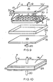
- Fig. 9 depicts a box-style flow-through capacitor.
- High surface area electrodes 1 are rectangular shaped, and are spaced apart by spacers 3. Spacers in Fig. 9 are depicted as shims, but may also be thin rods, threads, nets or open mesh, protrusions, or an outside scaffold.
- Integral leads extend from electrodes 1, and are bundled together in parallel, anode to anode and cathode to cathode, against electrode lead collectors 28.
- Electrode lead collectors are screw tightened against inside lid 15 and washers 29 with fasteners 30 to form an electrical connection with wire leads 14.
- the capacitor is placed snug inside box 26, which may be polygonal or circular in shape. Leak proof lids 15 with inlets 19 and outlets 20 are fitted onto box 26.
- Fig. 10 depicts the assembled flow-through capacitor of Fig. 9.
- the flow path is in through the inlet, between spaced apart high surface area layers 1.
- the high surface area layers may sandwich a conductive backing.
- Fig. 11 depicts a rod-type electrode design.
- the conductive, high surface area material 1 is in the shape of circular or polygonal, e.g. hexagonal, rods. This conductive material may have a central conductive rod or tube 32, to form a conductive backing for the high surface area material.
- High surface area electrodes 1 are spaced apart by spacer scaffold 33 connecting central conductive rods 32. Alternatively, the high surface area electrodes 1 may be spaced apart by protrusions or shims 34.
- Wire leads 14 connect alternating electrodes anode to anode and cathode to cathode in parallel connection. This forms anode/cathode pairs exactly similar to flat electrode designs. Wire leads 14 are attached to central conductive rods 32 via metal cap connector 31.
- the metal cap connectors 31 are preferably an inert metal, such as gold or platinum, and form a compression fitting where the central conductive rods 32 are graphite. Central conductive rods may be any inert conductive material. Where the central conductive rods 32 are metallic, metal cap connectors 31 can be omitted and the rod may simply be drawn out or directly attached to wires 14.
- Fig. 12 is an illustration of an assembled rod-style capacitor with rods sealed together with shrink wrap plastic tube 22 and held against cartridge holder 17 with leak proof O-ring 21. Wire leads extend in leak tight fashion through lid 15, which seals against cartridge holder 17. Flow is through inlet 19, between spaced apart high surface area conductive polygonal electrodes, and out through outlet 20.
- Figs. 13A-F depict various monolithic electrode designs that incorporate an inner conductive backing. This is useful for all the above flow-through capacitors because a compression fitting is no longer required to make a contact between the high surface area layers and the conductive backing layers.
- the electrodes of Fig. 13 contain an inner conductive backing layer 2, which may be a metal foil, graphite foil, a fibrous material, or an interpenetrating network mesh material. In foil form, this backing material has many holes 35 therethrough to allow communication and interconnection with the high surface area material that forms a sandwich on both sides in a flat electrode.
- a rod-style conductor can be used, with the high surface area material 1 formed directly around a central rod or wire conductor 32.
- This material is bonded together or calcined as a single, monolithic piece, containing the conductive backing internally.
- activated carbon or aerogel powder may be mixed with a phenolic binder and hot pressed to form the shapes in Fig. 13, prior to calcining in the absence of air.
- the interconnections formed through the holes in the conductive backing hold the high surface area material together and prevent it from pulling away from the backing due to shrinkage during calcining.
- carbon films or layers may be deposited onto conductive backings, and activated in place. Integral leads 4 are formed from the internal conductive backing layer or rod 32.
- Fig. 14 represents a diagram of a flow-through capacitor system.
- the flow-through capacitor 36 connected to manifold valves 37 and DC power supply 40 are controlled by computer or programmable logic 39.
- the feed solution 49 contains solution that is pumped or fed through capacitor 36 during the charge cycle to form purified product.
- Hold-up tank 46 pools the product flow produced during the charge cycles to provide an averaged, continuous product flow 53.
- Counter 55 measures how much current versus time flows into the capacitor, preforms an integral of current versus time to calculate charge, and automatically starts the discharge cycle after a preprogrammed amount of charge has passed into the capacitor. This charge is a cutoff point that corresponds with a desired level of saturation of the capacitor.
- the capacitor may also be controlled with sensors that monitor conductivity, pH, or concentration of feed, product, and waste solution.
- the power supply is first disconnected, and, after a short time interval for safety purposes, the capacitor is discharged through a load.
- waste solution stored in tank 43 is shunted through three way valves 38 and manifold valves 37 and pumped through the capacitor in a loop back into settling tank 41.
- the ions absorbed during the charge cycle of the capacitor are desorbed and discharged into this waste solution during discharge of the capacitor.
- the waste stream 50 gradually becomes saturated or supersaturated.
- Settling tank 41 is fitted with a heat exchanger 44 which functions to change the temperature of super-saturated wastes in order to provoke crystallization from solution.
- Crystals 42 that flow into or form in the tank 41 settle to the bottom, where they may be recovered through outlet 73.
- the saturated waste is decanted into tank 43, for use in the next discharge cycle.
- Saturated waste may be bled off directly through outlet 52. This may be replaced with make up solution through make up loop 51, which cross connects with feed stream 49.
- After discharge of the capacitor, saturated waste is returned to the tanks 41 and 43.
- Manifold valves 37 then actuate to close off the capacitor to both the waste and the feed streams, and open it up to a compressed gas stream 47.
- This gas stream displaces the waste solution from the capacitor, where it is driven into gas separation tank 56.
- Saturated waste liquid from tank 56 is recombined with the saturated waste stream through three way valve 57.
- Gas is exported from tank through outlet 48. It may also be desirable to likewise displace the feed solution with compressed gas after a charge cycle.
- Compressed gas stream 47 may be replaced with steam, which reactivates activated carbon electrodes and sterilizes the capacitor from microorganisms.
- Shunting loop 58 allows the direction of the feed solution through the capacitor to be reversed on alternate charge cycles in order to backwash the capacitor. This further prevents net build up of turbidity and foulant. All liquid solutions should first be fed into the bottom of the capacitor in order to displace all of the air, after which the flow may be maintained in this direction or reversed via shunting loop 58 to provide a backwash cycle.
- reconditioning tank 45 contains reconditioning solutions that are used to remove such absorbed materials, such as metals which electroplate onto the electrodes, organic foulants, or microbiological contaminants. It may also be important to adjust the pH of the feed solution, especially when dealing with easily plated metals. The object is to adjust the pH or add other ingredients to the feed solution in order to keep the plating voltage as high as possible. This allows the capacitor to operate more effectively via its capacitance mode and electrostatic absorption rather than by electrowinning and electroplating of metals onto the electrodes. Electroplated metals require acids, bases, oxidizers, solvents, or other additional chemicals to recondition the electrodes and recover the plated metals, via reconditioning tank 45. As desired, a pump 75 may be included along feed streams, such as feed stream 49; waste streams, such as waste stream 50; or any other streams.
- Fig. 15 shows a multiple capacitor system, with continuously charging and discharging capacitors to achieve continues product flow, as opposed to the single capacitor and flow averaging tank of Fig. 14.
- the flow path of capacitors 36 may either be connected in parallel, or may alternatively be connected in series through shunt 54. Series connection of the flow path allows successive staged purification of a concentrated solution to very high purity product solution 53. Other components function and are as numbered in Fig. 14.
- baffles in one or more or all of the flow passages to create a flow turbulence to the fluid through the flow passages to scour the surfaces to discharge foulants or to remove foulants from the flow passages.
- the value of the use of baffles for flow turbulence should be balanced with any pressure drop which results from the use of such baffles.
- baffles can be formed between the electrode layers, either constitutively with the electrode material or more easily with the spacer material. Increasing the flow rate of the capacitor may also be desired.
- the baffles create turbulence, which scours foulants from the electrode surface.
- Organic foulants tend to accumulate on the electrode surface. Microorganisms tend to grow and multiply on the electrodes, especially activated carbon. Temporarily running the capacitor at a high enough voltage to cause the electrolysis will actively clean the electrodes. Also, continuously running the capacitor at a slight over-voltage to cause continuously a little electrolysis will also keep the electrodes clean.
- the capacitor may be part of a train that includes other water purification technologies, including electrowinning, ion exchange, RO, ED, microfiltration and ultrafiltration, either upstream or downstream in the capacitor.
- other water purification technologies including electrowinning, ion exchange, RO, ED, microfiltration and ultrafiltration, either upstream or downstream in the capacitor.
- microfilters as a prefilter to remove fouling causing turbidity, or as a postfilter to remove carbon fines.
- a granular activated carbon prefilter may be desirable to further protect the capacitor from organic foulants.
- Greensand or oxidation means may be employed upstream of the capacitor to remove iron, which forms a slimy hydroxide that would tend to foul the capacitor.
- To produce ultrapure water it may also be desirable to include a deionization ion exchange bed downstream of the capacitor as a final polishing step.
- a stacked washer flow-through capacitor of Fig. 2 was assembled using sintered activated carbon for the high surface area layer (l) and 0.0127 cm (5 mil) thick graphite foil from Polycarbon for the conductive backing (2).
- the sintered activated carbon washers were obtained from Kansai Coke and Chemicals, Ltd. These washers had an outside diameter of 3.81 cm (1.5 inches) and an inside diameter of 1.9 cm (0.75 inches). They were 0.117cm (0.046 inches) thick.
- the specific density was .7 grams/ml, and the ratio of activated carbon to binder was 7:3.
- the activated carbon used had a BET surface area of 2000 square meters per gram.
- the central tube was 2.54 cm (1 inch) long, 0.953 cm (3/8 inch) OD, and 0.64 cm (1/4 inch) ID PVC, with holes drilled in the side with end threads (6).
- End caps were 0.64 cm (0.25 inch) thick PVC, 4.57 cm (1.8 inch) diameter, with internal threads that allow the end caps (7) to screw onto both ends of the central tube (5).
- Spacers consisted of six Teflon shims 1.9 cm (0.75 inches) long, 0.16 cm (1/16 inch) wide, and 0.0254 cm (0.01 inches) thick. These were laid out radially on top of the electrodes, as depicted on Fig. 3D.
- the anode and cathode electrodes where formed of ten sintered carbon washers of ten grams total which formed four intermediate double-sided electrodes, with the sintered activated carbon conductive high surface area material (1) sandwiching the conductive backing (2), and two single sided end electrodes with the conductive backing on the outside, between the sintered activated carbon conductive .high surface area material (1) and the end caps (7).
- Tabs (4) formed integral to the conductive. backing layers (2) where gathered up to form anode and cathode leads, which were connected via a gold compression contact to wire leads which led to a DC power supply.
- This capacitor was not placed inside a cartridge holder.
- One end of the central tube was sealed with urethane resin.
- the other end was connected to a length of plastic tubing, which in turn led to a pump.
- the flow-through capacitor was placed inside an open 200 ml container of feed solution, which was pumped through the capacitor under negative pressure.
- the tubing end could be placed in the feed solution, and solution could be pumped through under positive pressure.
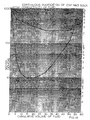
- Fig. 16 graphically illustrates Experiments 1 and 2 with non-saturated NaCl feed to demonstrate the utility of the present invention. These experiments used the flow-through capacitor described above in Example 1.
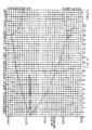
- Fig. 17 graphically illustrates Experiment 3 which tests the utility of the present invention with a saturated feed stream.
- the capacitor used in Experiment 3 is as described in Example 1 above.
- Saturated CaSO 4 is made by mixing distilled water with an excess of CaSO 4 and letting the mixture sit on the excess solids overnight.
- a capacitor is connected to one of the two 200 ml saturated CaSO 4 solutions and run in batch mode at 2 volts for five minutes. Air is then pumped through the capacitor until capacitor is completely drained. Solution from the second 200 ml volume of saturated CaSO 4 is then pumped through the capacitor while simultaneously short circuiting the capacitor. This process is repeated twenty times, always reusing the same solutions for the purification cycle and concentration cycle. Polarity was reversed between every charge cycle.
- a graph of the results is depicted on Fig. 17.
- the batch purified solution is purified down to 802 micro Siemens.
- the batch concentrated solution is concentrated up to 2470 micro Siemens. This concentrated solution has become super saturated. Upon raising the temperature of this super saturated solution in a hot water bath, crystals were observed to drop out of solution. Decanting this solution provides a saturated solution which can be saved and reused as a regeneration stream. The separated crystals may be collected as a solid waste.
Landscapes
- Chemical & Material Sciences (AREA)
- Life Sciences & Earth Sciences (AREA)
- Analytical Chemistry (AREA)
- Health & Medical Sciences (AREA)
- Chemical Kinetics & Catalysis (AREA)
- Physics & Mathematics (AREA)
- Biochemistry (AREA)
- General Health & Medical Sciences (AREA)
- General Physics & Mathematics (AREA)
- Immunology (AREA)
- Pathology (AREA)
- Organic Chemistry (AREA)
- Molecular Biology (AREA)
- General Chemical & Material Sciences (AREA)
- Hydrology & Water Resources (AREA)
- Engineering & Computer Science (AREA)
- Environmental & Geological Engineering (AREA)
- Water Supply & Treatment (AREA)
- Electrochemistry (AREA)
- Water Treatment By Electricity Or Magnetism (AREA)
- Fixed Capacitors And Capacitor Manufacturing Machines (AREA)
- Supply And Distribution Of Alternating Current (AREA)
- Electrical Discharge Machining, Electrochemical Machining, And Combined Machining (AREA)
- Registering, Tensioning, Guiding Webs, And Rollers Therefor (AREA)
- Engine Equipment That Uses Special Cycles (AREA)
Applications Claiming Priority (3)
| Application Number | Priority Date | Filing Date | Title |
|---|---|---|---|
| US541880 | 1995-10-10 | ||
| US08/541,880 US5620597A (en) | 1990-04-23 | 1995-10-10 | Non-fouling flow-through capacitor |
| PCT/US1996/016157 WO1997013568A1 (en) | 1995-10-10 | 1996-10-09 | Non-fouling, flow-through capacitor, system and method of separation |
Publications (3)
| Publication Number | Publication Date |
|---|---|
| EP0861114A1 EP0861114A1 (en) | 1998-09-02 |
| EP0861114A4 EP0861114A4 (en) | 1999-07-07 |
| EP0861114B1 true EP0861114B1 (en) | 2005-03-23 |
Family
ID=24161481
Family Applications (1)
| Application Number | Title | Priority Date | Filing Date |
|---|---|---|---|
| EP96936279A Expired - Lifetime EP0861114B1 (en) | 1995-10-10 | 1996-10-09 | Non-fouling, flow-through capacitor, system and method of separation |
Country Status (8)
| Country | Link |
|---|---|
| US (2) | US5620597A (enExample) |
| EP (1) | EP0861114B1 (enExample) |
| JP (2) | JP4790878B2 (enExample) |
| AT (1) | ATE291494T1 (enExample) |
| AU (1) | AU706578B2 (enExample) |
| DE (1) | DE69634516T2 (enExample) |
| ES (1) | ES2241005T3 (enExample) |
| WO (1) | WO1997013568A1 (enExample) |
Cited By (2)
| Publication number | Priority date | Publication date | Assignee | Title |
|---|---|---|---|---|
| EP2341032A2 (de) | 2009-12-15 | 2011-07-06 | Schnider, Kurt | Vorrichtung und Verfahren zur Aufbereitung von Wasser für die Speisung eines Durchflusskondensators |
| US8730650B2 (en) | 2007-11-13 | 2014-05-20 | Voltea Limited | Water purification device |
Families Citing this family (155)
| Publication number | Priority date | Publication date | Assignee | Title |
|---|---|---|---|---|
| US6309532B1 (en) | 1994-05-20 | 2001-10-30 | Regents Of The University Of California | Method and apparatus for capacitive deionization and electrochemical purification and regeneration of electrodes |
| EP1027716B1 (en) * | 1996-12-12 | 2006-05-10 | Corning Incorporated | Activated carbon electrodes for electrical double layer capacitors |
| US6805776B2 (en) * | 2001-08-07 | 2004-10-19 | Inventqjaya Sdn Bhd | Movable electrode flow through capacitor |
| US6127474A (en) * | 1997-08-27 | 2000-10-03 | Andelman; Marc D. | Strengthened conductive polymer stabilized electrode composition and method of preparing |
| US6598459B1 (en) * | 1998-01-09 | 2003-07-29 | Chi Yung Fu | Artificial olfactory system |
| US5980718A (en) * | 1998-05-04 | 1999-11-09 | The Regents Of The University Of California | Means for limiting and ameliorating electrode shorting |
| US6413409B1 (en) * | 1998-09-08 | 2002-07-02 | Biosource, Inc. | Flow-through capacitor and method of treating liquids with it |
| JP4286931B2 (ja) * | 1998-09-08 | 2009-07-01 | バイオソース・インコーポレーテッド | 通液型コンデンサおよびそれを用いた液体の処理方法 |
| US6346187B1 (en) | 1999-01-21 | 2002-02-12 | The Regents Of The University Of California | Alternating-polarity operation for complete regeneration of electrochemical deionization system |
| CN1246869C (zh) * | 1999-07-30 | 2006-03-22 | 马奇·D·安德曼 | 流通电容器和方法 |
| US6778378B1 (en) | 1999-07-30 | 2004-08-17 | Biosource, Inc. | Flow-through capacitor and method |
| WO2001013389A1 (en) * | 1999-08-13 | 2001-02-22 | Andelman Marc D | Flow-through capacitor, system and method |
| US6214204B1 (en) | 1999-08-27 | 2001-04-10 | Corning Incorporated | Ion-removal from water using activated carbon electrodes |
| AUPQ253099A0 (en) * | 1999-08-30 | 1999-09-23 | Energy Storage Systems Pty Ltd | A charge storage device |
| US6325907B1 (en) | 1999-10-18 | 2001-12-04 | Marc D. Andelman | Energy and weight efficient flow-through capacitor, system and method |
| US6477404B1 (en) | 2000-03-01 | 2002-11-05 | Cardiac Pacemakers, Inc. | System and method for detection of pacing pulses within ECG signals |
| WO2001066217A1 (en) * | 2000-03-06 | 2001-09-13 | Andelman Marc D | Low pore volume electrodes with flow-through capacitor and energy storage use and method |
| US6410128B1 (en) | 2000-03-13 | 2002-06-25 | Graftech Inc. | Flexible graphite capacitor element |
| US6627252B1 (en) | 2000-05-12 | 2003-09-30 | Maxwell Electronic Components, Inc. | Electrochemical double layer capacitor having carbon powder electrodes |
| US6631074B2 (en) | 2000-05-12 | 2003-10-07 | Maxwell Technologies, Inc. | Electrochemical double layer capacitor having carbon powder electrodes |
| WO2001089656A1 (en) * | 2000-05-22 | 2001-11-29 | Abb Power T & D Company Inc. | Capacitive deionization cell power supply |
| US6628505B1 (en) | 2000-07-29 | 2003-09-30 | Biosource, Inc. | Flow-through capacitor, system and method |
| AU2001296470A1 (en) * | 2000-10-02 | 2002-04-15 | Marc D. Andelman | Fringe-field capacitor electrode for electrochemical device |
| US6833987B1 (en) * | 2000-11-03 | 2004-12-21 | Cardiac Pacemakers, Inc. | Flat capacitor having an active case |
| US6699265B1 (en) | 2000-11-03 | 2004-03-02 | Cardiac Pacemakers, Inc. | Flat capacitor for an implantable medical device |
| US7107099B1 (en) * | 2000-11-03 | 2006-09-12 | Cardiac Pacemakers, Inc. | Capacitor having a feedthrough assembly with a coupling member |
| US6522525B1 (en) | 2000-11-03 | 2003-02-18 | Cardiac Pacemakers, Inc. | Implantable heart monitors having flat capacitors with curved profiles |
| US7355841B1 (en) * | 2000-11-03 | 2008-04-08 | Cardiac Pacemakers, Inc. | Configurations and methods for making capacitor connections |
| US6687118B1 (en) * | 2000-11-03 | 2004-02-03 | Cardiac Pacemakers, Inc. | Flat capacitor having staked foils and edge-connected connection members |
| US6571126B1 (en) | 2000-11-03 | 2003-05-27 | Cardiac Pacemakers, Inc. | Method of constructing a capacitor stack for a flat capacitor |
| US6509588B1 (en) * | 2000-11-03 | 2003-01-21 | Cardiac Pacemakers, Inc. | Method for interconnecting anodes and cathodes in a flat capacitor |
| US6684102B1 (en) * | 2000-11-03 | 2004-01-27 | Cardiac Pacemakers, Inc. | Implantable heart monitors having capacitors with endcap headers |
| US7456077B2 (en) * | 2000-11-03 | 2008-11-25 | Cardiac Pacemakers, Inc. | Method for interconnecting anodes and cathodes in a flat capacitor |
| JP2002175837A (ja) * | 2000-12-06 | 2002-06-21 | Nisshinbo Ind Inc | 高分子ゲル電解質及び二次電池並びに電気二重層キャパシタ |
| US6580598B2 (en) | 2001-02-15 | 2003-06-17 | Luxon Energy Devices Corporation | Deionizers with energy recovery |
| KR100442773B1 (ko) * | 2001-03-29 | 2004-08-04 | 한국에너지기술연구원 | 전기흡착 방식의 담수화방법 및 장치 |
| US6709560B2 (en) | 2001-04-18 | 2004-03-23 | Biosource, Inc. | Charge barrier flow-through capacitor |
| CN100518910C (zh) * | 2001-04-18 | 2009-07-29 | 拜奥资源公司 | 流通电容器 |
| US20040121204A1 (en) * | 2001-06-07 | 2004-06-24 | Adelman Marc D. | Fluid electrical connected flow-through electrochemical cells, system and method |
| US7368191B2 (en) | 2001-07-25 | 2008-05-06 | Biosource, Inc. | Electrode array for use in electrochemical cells |
| NZ520231A (en) * | 2001-08-08 | 2003-11-28 | Tyk Corp | Water purifier with sintered activated carbon/ceramic filter block |
| US6630073B1 (en) | 2001-08-29 | 2003-10-07 | Eugene A. Moskal | Sonic contaminated resource treatment method and apparatus |
| EP1291323B1 (en) * | 2001-09-10 | 2006-07-12 | Lih-Ren Shiue | Replaceable flow-through capacitors for removing charged species from liquids |
| US6643119B2 (en) | 2001-11-02 | 2003-11-04 | Maxwell Technologies, Inc. | Electrochemical double layer capacitor having carbon powder electrodes |
| AU2002357251B2 (en) * | 2001-12-21 | 2009-07-30 | Dow Global Technologies Inc. | Additive for rendering inert acidic or halogen-containing compounds contained in olefin polymers |
| US20050011409A1 (en) * | 2001-12-25 | 2005-01-20 | Yasuhide Isobe | Inorganic oxide |
| US6790369B1 (en) | 2002-01-28 | 2004-09-14 | Universtiy Of South Florida | Apparatus and method for protecting toroidal conductivity sensors |
| EP1348670A1 (en) * | 2002-03-27 | 2003-10-01 | Luxon Energy Devices Corporation | Fully automatic and energy-efficient capacitive deionizer |
| JP2003285066A (ja) * | 2002-03-27 | 2003-10-07 | Luxon Energy Devices Corp | エネルギー回収をともなう純水装置 |
| US6871014B2 (en) | 2002-04-26 | 2005-03-22 | The Coca-Cola Company | Water treatment system and water heater with cathodic protection and method |
| MXPA04010133A (es) * | 2002-05-07 | 2005-01-25 | Coca Cola Co | Aparato para tratamiento de agua, auto-esterilizante, con deposito para agua tratada que incluye un elemento calefactor. |
| US7029563B2 (en) * | 2002-07-30 | 2006-04-18 | Zhejiang Omex Environmental Engineering Ltd. | EDI device with composite electrode |
| TW200427634A (en) * | 2002-10-25 | 2004-12-16 | Inventqjaya Sdn Bhd | Fluid deionization system |
| US7016462B1 (en) | 2002-11-08 | 2006-03-21 | Interscience, Inc. | Ionic pre-concentration XRF identification and analysis device, system and method |
| US6830595B2 (en) * | 2002-12-20 | 2004-12-14 | Advanced Energy Technology Inc. | Method of making composite electrode and current collectors |
| US20040118780A1 (en) * | 2002-12-20 | 2004-06-24 | Barnstead/Thermolyne Corporation | Water purification system and method |
| US7206189B2 (en) * | 2002-12-20 | 2007-04-17 | Advanced Energy Technology Inc. | Composite electrode and current collectors and processes for making the same |
| US7951479B2 (en) | 2005-05-11 | 2011-05-31 | Cardiac Pacemakers, Inc. | Method and apparatus for porous insulative film for insulating energy source layers |
| US7479349B2 (en) * | 2002-12-31 | 2009-01-20 | Cardiac Pacemakers, Inc. | Batteries including a flat plate design |
| US20040158291A1 (en) * | 2003-02-07 | 2004-08-12 | Polkinghorne Jeannette C. | Implantable heart monitors having electrolytic capacitors with hydrogen-getting materials |
| US7000409B2 (en) * | 2003-05-23 | 2006-02-21 | Marit Jagtoyen Mazzetti | Use of flow through capacitor in the recovery and purification of water from exhaust gases of internal combustion engines |
| US7791860B2 (en) | 2003-07-09 | 2010-09-07 | Maxwell Technologies, Inc. | Particle based electrodes and methods of making same |
| US7352558B2 (en) | 2003-07-09 | 2008-04-01 | Maxwell Technologies, Inc. | Dry particle based capacitor and methods of making same |
| AU2004264223B2 (en) * | 2003-08-06 | 2009-07-23 | Biosource, Inc | Power efficient flow through capacitor system |
| US7920371B2 (en) | 2003-09-12 | 2011-04-05 | Maxwell Technologies, Inc. | Electrical energy storage devices with separator between electrodes and methods for fabricating the devices |
| US7090946B2 (en) | 2004-02-19 | 2006-08-15 | Maxwell Technologies, Inc. | Composite electrode and method for fabricating same |
| US7224575B2 (en) | 2004-07-16 | 2007-05-29 | Cardiac Pacemakers, Inc. | Method and apparatus for high voltage aluminum capacitor design |
| US7180727B2 (en) * | 2004-07-16 | 2007-02-20 | Cardiac Pacemakers, Inc. | Capacitor with single sided partial etch and stake |
| US20060049105A1 (en) * | 2004-09-07 | 2006-03-09 | Marine Desalination Systems, L.L.C. | Segregated flow, continuous flow deionization |
| WO2006074277A1 (en) * | 2005-01-06 | 2006-07-13 | Biosource, Inc. | Surfactant combined flow through capacitor |
| EP1848668A4 (en) * | 2005-02-07 | 2008-06-25 | Bauer Energy Design Inc | SYSTEMS AND METHODS FOR THE TREATMENT OF LIQUID SOLUTIONS INTENDED FOR LIVESTOCK |
| US7440258B2 (en) | 2005-03-14 | 2008-10-21 | Maxwell Technologies, Inc. | Thermal interconnects for coupling energy storage devices |
| US7301753B2 (en) | 2005-05-09 | 2007-11-27 | Cardiac Pacemakers, Inc. | Method and apparatus for a capacitor with flexible bus |
| US7206191B2 (en) * | 2005-05-09 | 2007-04-17 | Cardiac Pacemakers, Inc. | Method and apparatus for electrically isolating capacitor electrodes using separator |
| WO2006132160A1 (ja) * | 2005-06-08 | 2006-12-14 | Tanah Process Ltd. | 液体のpH調整方法およびpH調整装置 |
| WO2007037193A1 (ja) | 2005-09-27 | 2007-04-05 | Tanah Process Ltd. | イオン濃度調整方法およびイオン濃度調整装置 |
| US7891046B2 (en) * | 2006-02-10 | 2011-02-22 | Tennant Company | Apparatus for generating sparged, electrochemically activated liquid |
| US8046867B2 (en) | 2006-02-10 | 2011-11-01 | Tennant Company | Mobile surface cleaner having a sparging device |
| US8012340B2 (en) * | 2006-02-10 | 2011-09-06 | Tennant Company | Method for generating electrochemically activated cleaning liquid |
| US8156608B2 (en) * | 2006-02-10 | 2012-04-17 | Tennant Company | Cleaning apparatus having a functional generator for producing electrochemically activated cleaning liquid |
| US8016996B2 (en) * | 2006-02-10 | 2011-09-13 | Tennant Company | Method of producing a sparged cleaning liquid onboard a mobile surface cleaner |
| US7836543B2 (en) * | 2006-02-10 | 2010-11-23 | Tennant Company | Method and apparatus for producing humanly-perceptable indicator of electrochemical properties of an output cleaning liquid |
| US8025787B2 (en) | 2006-02-10 | 2011-09-27 | Tennant Company | Method and apparatus for generating, applying and neutralizing an electrochemically activated liquid |
| US8007654B2 (en) * | 2006-02-10 | 2011-08-30 | Tennant Company | Electrochemically activated anolyte and catholyte liquid |
| US8025786B2 (en) * | 2006-02-10 | 2011-09-27 | Tennant Company | Method of generating sparged, electrochemically activated liquid |
| EP2036863A1 (en) * | 2006-05-12 | 2009-03-18 | Tanah Process Ltd. | Process for producing conductive substance with ion adsorbed thereon, method of regulating ion concentration, and ion supply source |
| CA2659394A1 (en) * | 2006-07-17 | 2008-07-10 | Vecenergy Aegir, Llc | Microscale capacitive deionization apparatus |
| US8761875B2 (en) | 2006-08-03 | 2014-06-24 | Cardiac Pacemakers, Inc. | Method and apparatus for selectable energy storage partitioned capacitor |
| WO2008049037A2 (en) * | 2006-10-17 | 2008-04-24 | Maxwell Technologies, Inc. | Electrode for energy storage device |
| US7813106B2 (en) | 2006-12-19 | 2010-10-12 | General Electric Company | High current efficiency supercapacitor desalination devices and methods of making the same |
| US20080185294A1 (en) * | 2007-02-01 | 2008-08-07 | General Electric Company | Liquid management method and system |
| US7974076B2 (en) * | 2007-02-01 | 2011-07-05 | General Electric Company | Desalination device and associated method |
| AU2007345554B2 (en) * | 2007-02-01 | 2012-07-19 | General Electric Company | Desalination method and device comprising supercapacitor electrodes |
| KR20100041773A (ko) * | 2007-06-18 | 2010-04-22 | 텐난트 컴파니 | 알콜 제조 시스템 및 방법 |
| US8337690B2 (en) * | 2007-10-04 | 2012-12-25 | Tennant Company | Method and apparatus for neutralizing electrochemically activated liquids |
| US8341736B2 (en) * | 2007-10-12 | 2012-12-25 | Microsoft Corporation | Detection and dynamic alteration of execution of potential software threats |
| US20090120460A1 (en) * | 2007-11-09 | 2009-05-14 | Tennant Company | Soft floor pre-spray unit utilizing electrochemically-activated water and method of cleaning soft floors |
| US8871074B2 (en) | 2007-12-19 | 2014-10-28 | Massachusetts Institute Of Technology | Method and apparatus for permeating flow desalination |
| CN101980968B (zh) * | 2008-03-25 | 2012-10-31 | 棚氏处理有限公司 | 用于调节饮用水硬度的携带式硬度调节装置 |
| WO2009149327A2 (en) * | 2008-06-05 | 2009-12-10 | Global Opportunities Investment Group, Llc | Fuel combustion method and system |
| EP2291246A2 (en) * | 2008-06-10 | 2011-03-09 | Tennant Company | Steam cleaner using electrolyzed liquid and method therefor |
| US20090311137A1 (en) * | 2008-06-11 | 2009-12-17 | Tennant Company | Atomizer using electrolyzed liquid and method therefor |
| WO2009155528A1 (en) * | 2008-06-19 | 2009-12-23 | Tennant Company | Electrolysis de-scaling method with constant output |
| WO2009155521A1 (en) * | 2008-06-19 | 2009-12-23 | Tennant Company | Tubular electrolysis cell comprising concentric electrodes and corresponding method |
| US20110108437A1 (en) * | 2008-06-23 | 2011-05-12 | Tanah Process Ltd. | Disinfection method and disinfection device |
| US7935259B2 (en) * | 2008-07-03 | 2011-05-03 | The United States Of America As Represented By The Administrator Of The National Aeronautics And Space Administration | Filtering apparatus and method of use |
| US8343403B2 (en) * | 2008-07-16 | 2013-01-01 | The United States Of America As Represented By The Administrator Of The National Aeronautics And Space Administration | Method for making a microporous membrane |
| US8470152B2 (en) * | 2008-09-15 | 2013-06-25 | Voltea B.V. | Method of operating a capacitive deionization cell using gentle charge |
| WO2010030376A1 (en) * | 2008-09-15 | 2010-03-18 | Gore Enterprise Holdings, Inc. | Method of operating a capacitive deionization cell using a relatively slow discharge flow rate |
| AU2009292206A1 (en) * | 2008-09-15 | 2010-03-18 | Voltea B.V. | Method of regenerating a capacitive deionization cell |
| US8333887B2 (en) * | 2008-10-23 | 2012-12-18 | General Electric Company | Methods and systems for purifying aqueous liquids |
| JP2012512333A (ja) * | 2008-12-17 | 2012-05-31 | テナント カンパニー | 消毒特性を強化するために液体を通じて電荷を印加する方法および装置 |
| US8518253B2 (en) * | 2008-12-17 | 2013-08-27 | General Electric Company | Ion-exchange device and regeneration method of ion-exchange material thereof |
| US8371315B2 (en) | 2008-12-17 | 2013-02-12 | Tennant Company | Washing systems incorporating charged activated liquids |
| US8864911B2 (en) | 2009-03-26 | 2014-10-21 | General Electric Company | Method for removing ionic species from desalination unit |
| US20110011749A1 (en) * | 2009-07-20 | 2011-01-20 | Christian Gollmann | Process for separation of an ion from a fluid mixture |
| US20110024354A1 (en) * | 2009-07-30 | 2011-02-03 | General Electric Company | Desalination system and method |
| US8636889B2 (en) * | 2009-08-20 | 2014-01-28 | General Electric Company | Solid electrolyte producing assembly and method |
| US20110048959A1 (en) * | 2009-08-31 | 2011-03-03 | Tennant Company | Electrochemically-Activated Liquids Containing Fragrant Compounds |
| US20110056843A1 (en) | 2009-09-08 | 2011-03-10 | Patrick Michael Curran | Concentric layer electric double layer capacitor cylinder, system, and method of use |
| GB0921953D0 (en) * | 2009-12-16 | 2010-02-03 | Enpar Technologies Inc | Flow-through electro static water filter |
| US8619408B2 (en) | 2009-12-18 | 2013-12-31 | Cardiac Pacemakers, Inc. | Sintered capacitor electrode including a folded connection |
| IT1398663B1 (it) * | 2010-02-24 | 2013-03-08 | Idropan Dell Orto Depuratori Srl | Metodo per la purificazione di un fluido mediante un condensatore a flusso passante, ed apparecchiatura per la purificazione di un fluido, in particolare atta alla realizzazione di tale metodo. |
| CN102906028B (zh) * | 2010-05-17 | 2014-11-12 | 沃尔泰亚公司 | 去除离子的装置以及去除离子的方法 |
| EP2420478A1 (en) * | 2010-08-17 | 2012-02-22 | Koninklijke Philips Electronics N.V. | Method and device for purifying water |
| CA2853027C (en) | 2010-10-22 | 2023-03-14 | Ionic Solutions Ltd. | Apparatus and process for separation and selective recomposition of ions |
| US9637397B2 (en) | 2011-10-27 | 2017-05-02 | Pentair Residential Filtration, Llc | Ion removal using a capacitive deionization system |
| US9010361B2 (en) | 2011-10-27 | 2015-04-21 | Pentair Residential Filtration, Llc | Control valve assembly |
| US8961770B2 (en) * | 2011-10-27 | 2015-02-24 | Pentair Residential Filtration, Llc | Controller and method of operation of a capacitive deionization system |
| US9695070B2 (en) * | 2011-10-27 | 2017-07-04 | Pentair Residential Filtration, Llc | Regeneration of a capacitive deionization system |
| US8671985B2 (en) | 2011-10-27 | 2014-03-18 | Pentair Residential Filtration, Llc | Control valve assembly |
| ITPD20120239A1 (it) | 2012-08-02 | 2014-02-03 | Idropan Dell Orto Depuratori Srl | Metodo ed apparecchiatura per il trattamento di un fluido contenente particelle ionizzate |
| EP2692698B1 (en) * | 2012-08-02 | 2015-01-14 | Voltea B.V. | A method and an apparatus to remove ions |
| EP2754644A1 (en) * | 2013-01-15 | 2014-07-16 | Voltea B.V. | Evaporative recirculation cooling water system, method of operating an evaporative recirculation cooling water system and a method of operating a water deionizing system |
| US9633798B2 (en) | 2013-05-24 | 2017-04-25 | Atlantis Technologies | Atomic capacitor |
| US9859066B2 (en) | 2013-05-24 | 2018-01-02 | Atlantis Technologies | Atomic capacitor |
| KR102000500B1 (ko) | 2013-08-05 | 2019-07-18 | 웅진코웨이 주식회사 | Cdi 방식의 수처리 장치 |
| CN105592916B (zh) | 2013-10-03 | 2020-04-07 | 伊必得控股公司 | 包含纳米气泡的液体溶液 |
| ITPD20130280A1 (it) * | 2013-10-09 | 2015-04-10 | Idropan Dell Orto Depuratori S R L | Apparecchiatura per il trattamento di un fluido |
| WO2015101390A1 (en) | 2013-12-30 | 2015-07-09 | Electrolux Appliances Aktiebolag | Laundry washing machine with water softening system and method for controlling a laundry washing machine |
| KR20150077673A (ko) * | 2013-12-30 | 2015-07-08 | 삼성디스플레이 주식회사 | 전자기기용 방열부재 |
| US10544536B2 (en) | 2013-12-30 | 2020-01-28 | Electrolux Appliances Aktiebolag | Laundry washing machine and method for controlling a laundry washing machine |
| WO2015101424A1 (en) | 2013-12-30 | 2015-07-09 | Electrolux Appliances Aktiebolag | Laundry washing machine and method for controlling a laundry washing machine |
| PL3090085T3 (pl) | 2013-12-30 | 2022-10-31 | Electrolux Appliances Aktiebolag | Pralka do prania z systemem zmiękczania wody oraz sposób sterowania pralką do prania |
| AU2014389040B2 (en) | 2014-04-01 | 2019-03-21 | Electrolux Appliances Aktiebolag | Water supply assembly for laundry washing machines |
| WO2016095401A1 (zh) * | 2014-12-19 | 2016-06-23 | 佛山市顺德区美的饮水机制造有限公司 | 一体复合滤芯和具有其的净水系统 |
| EP3037389B1 (en) | 2014-12-24 | 2018-05-16 | IDROPAN DELL'ORTO DEPURATORI S.r.l. | Apparatus for purifying a fluid and method for the attainment thereof |
| TWI609392B (zh) * | 2015-02-17 | 2017-12-21 | 鈺邦科技股份有限公司 | 高儲能電容單元 |
| JP6199001B1 (ja) * | 2016-01-12 | 2017-09-20 | 三菱電機株式会社 | 水処理装置及び水処理方法 |
| US11484822B2 (en) | 2016-01-27 | 2022-11-01 | Koch-Giltsch, LP | Inlet vane device and vessel containing same |
| WO2018226823A1 (en) | 2017-06-07 | 2018-12-13 | Erix Solutions Llc | Electrochemical ion exchange treatment of fluids |
| US10787378B2 (en) | 2018-05-30 | 2020-09-29 | Atlantis Technologies | Spirally wound electric double layer capacitor device and associated methods |
| CN110496543B (zh) * | 2019-08-28 | 2021-10-08 | 山东大学 | 一种二氧化硅-聚醚砜导电超滤膜的制备方法及其所得的超滤膜与应用 |
| US20220017388A1 (en) * | 2020-07-20 | 2022-01-20 | University Of Kentucky Research Foundation | Apparatus and method for enhanced capacitive deionization of contaminated water |
| KR102358882B1 (ko) * | 2021-04-29 | 2022-02-08 | 두산중공업 주식회사 | 탈염 전기흡착식 결정 제조방법 |
Citations (1)
| Publication number | Priority date | Publication date | Assignee | Title |
|---|---|---|---|---|
| US5425858A (en) * | 1994-05-20 | 1995-06-20 | The Regents Of The University Of California | Method and apparatus for capacitive deionization, electrochemical purification, and regeneration of electrodes |
Family Cites Families (9)
| Publication number | Priority date | Publication date | Assignee | Title |
|---|---|---|---|---|
| US3658674A (en) * | 1966-02-28 | 1972-04-25 | Standard Oil Co Ohio | Process for demineralization of water |
| US5200068A (en) * | 1990-04-23 | 1993-04-06 | Andelman Marc D | Controlled charge chromatography system |
| US5360540A (en) * | 1990-04-23 | 1994-11-01 | Andelman Marc D | Chromatography system |
| US5196115A (en) * | 1990-04-23 | 1993-03-23 | Andelman Marc D | Controlled charge chromatography system |
| US5192432A (en) * | 1990-04-23 | 1993-03-09 | Andelman Marc D | Flow-through capacitor |
| US5415768A (en) * | 1990-04-23 | 1995-05-16 | Andelman; Marc D. | Flow-through capacitor |
| US5384685A (en) * | 1992-09-18 | 1995-01-24 | Pinnacle Research Institute, Inc. | Screen printing of microprotrusions for use as a space separator in an electrical storage device |
| US5538611A (en) * | 1993-05-17 | 1996-07-23 | Marc D. Andelman | Planar, flow-through, electric, double-layer capacitor and a method of treating liquids with the capacitor |
| JP3302443B2 (ja) * | 1993-05-17 | 2002-07-15 | 関西熱化学株式会社 | 平板形状の通液型電気二重層コンデンサおよびそれを用いた液体の処理方法 |
-
1995
- 1995-10-10 US US08/541,880 patent/US5620597A/en not_active Expired - Lifetime
-
1996
- 1996-10-09 WO PCT/US1996/016157 patent/WO1997013568A1/en not_active Ceased
- 1996-10-09 DE DE69634516T patent/DE69634516T2/de not_active Expired - Lifetime
- 1996-10-09 JP JP51514797A patent/JP4790878B2/ja not_active Expired - Lifetime
- 1996-10-09 AU AU14325/97A patent/AU706578B2/en not_active Expired
- 1996-10-09 AT AT96936279T patent/ATE291494T1/de not_active IP Right Cessation
- 1996-10-09 EP EP96936279A patent/EP0861114B1/en not_active Expired - Lifetime
- 1996-10-09 ES ES96936279T patent/ES2241005T3/es not_active Expired - Lifetime
-
1997
- 1997-04-15 US US08/834,259 patent/US5779891A/en not_active Expired - Lifetime
-
2008
- 2008-08-06 JP JP2008203404A patent/JP2009018305A/ja active Pending
Patent Citations (1)
| Publication number | Priority date | Publication date | Assignee | Title |
|---|---|---|---|---|
| US5425858A (en) * | 1994-05-20 | 1995-06-20 | The Regents Of The University Of California | Method and apparatus for capacitive deionization, electrochemical purification, and regeneration of electrodes |
Cited By (3)
| Publication number | Priority date | Publication date | Assignee | Title |
|---|---|---|---|---|
| US8730650B2 (en) | 2007-11-13 | 2014-05-20 | Voltea Limited | Water purification device |
| EP2341032A2 (de) | 2009-12-15 | 2011-07-06 | Schnider, Kurt | Vorrichtung und Verfahren zur Aufbereitung von Wasser für die Speisung eines Durchflusskondensators |
| DE102010054477A1 (de) | 2009-12-15 | 2011-07-07 | Schnider, Kurt | Vorrichtung und Verfahren zur Aufbereitung von Wasser |
Also Published As
| Publication number | Publication date |
|---|---|
| EP0861114A4 (en) | 1999-07-07 |
| DE69634516T2 (de) | 2006-03-16 |
| US5620597A (en) | 1997-04-15 |
| ES2241005T3 (es) | 2005-10-16 |
| WO1997013568A1 (en) | 1997-04-17 |
| US5779891A (en) | 1998-07-14 |
| JP4790878B2 (ja) | 2011-10-12 |
| AU706578B2 (en) | 1999-06-17 |
| JP2009018305A (ja) | 2009-01-29 |
| DE69634516D1 (de) | 2005-04-28 |
| ATE291494T1 (de) | 2005-04-15 |
| JPH11514289A (ja) | 1999-12-07 |
| AU1432597A (en) | 1997-04-30 |
| EP0861114A1 (en) | 1998-09-02 |
Similar Documents
| Publication | Publication Date | Title |
|---|---|---|
| EP0861114B1 (en) | Non-fouling, flow-through capacitor, system and method of separation | |
| EP0760805B1 (en) | Method and apparatus for capacitive deionization and electrochemical purification and regeneration of electrodes | |
| US6346187B1 (en) | Alternating-polarity operation for complete regeneration of electrochemical deionization system | |
| US6309532B1 (en) | Method and apparatus for capacitive deionization and electrochemical purification and regeneration of electrodes | |
| US20130056366A1 (en) | Apparatus and method for removal of ions from a porous electrode that is part of a deionization system | |
| US6778378B1 (en) | Flow-through capacitor and method | |
| US8002963B2 (en) | Charge barrier flow-through capacitor-based method of deionizing a fluid | |
| US20090045074A1 (en) | Apparatus and method for removal of ions from a porous electrode that is part of a deionization system | |
| US10202294B2 (en) | Concentric layer electric double layer capacitor cylinder, system, and method of use | |
| CA2444390C (en) | Charge barrier flow-through capacitor | |
| CN110809564B (zh) | 脱盐设备及其制造方法 | |
| WO2001009907A1 (en) | Flow-through capacitor and method | |
| JP2012086192A (ja) | 電気二重層キャパシタとこれを用いた脱イオン装置及びその運転方法 | |
| JPH081165A (ja) | 電解槽 | |
| CN115974240B (zh) | 膜电容去离子电极组件、外壳结构、模块及处理液体的方法 | |
| HK40024515A (en) | Desalination device and method of manufacturing such a device |
Legal Events
| Date | Code | Title | Description |
|---|---|---|---|
| PUAI | Public reference made under article 153(3) epc to a published international application that has entered the european phase |
Free format text: ORIGINAL CODE: 0009012 |
|
| 17P | Request for examination filed |
Effective date: 19980423 |
|
| AK | Designated contracting states |
Kind code of ref document: A1 Designated state(s): AT BE CH DE ES FR GB IT LI NL |
|
| A4 | Supplementary search report drawn up and despatched |
Effective date: 19990526 |
|
| AK | Designated contracting states |
Kind code of ref document: A4 Designated state(s): AT BE CH DE ES FR GB IT LI NL |
|
| RIC1 | Information provided on ipc code assigned before grant |
Free format text: 6B 01J 47/08 A, 6B 01D 15/00 B, 6G 01N 30/60 B |
|
| 17Q | First examination report despatched |
Effective date: 20020201 |
|
| GRAP | Despatch of communication of intention to grant a patent |
Free format text: ORIGINAL CODE: EPIDOSNIGR1 |
|
| GRAS | Grant fee paid |
Free format text: ORIGINAL CODE: EPIDOSNIGR3 |
|
| GRAA | (expected) grant |
Free format text: ORIGINAL CODE: 0009210 |
|
| AK | Designated contracting states |
Kind code of ref document: B1 Designated state(s): AT BE CH DE ES FR GB IT LI NL |
|
| PG25 | Lapsed in a contracting state [announced via postgrant information from national office to epo] |
Ref country code: LI Free format text: LAPSE BECAUSE OF FAILURE TO SUBMIT A TRANSLATION OF THE DESCRIPTION OR TO PAY THE FEE WITHIN THE PRESCRIBED TIME-LIMIT Effective date: 20050323 Ref country code: CH Free format text: LAPSE BECAUSE OF FAILURE TO SUBMIT A TRANSLATION OF THE DESCRIPTION OR TO PAY THE FEE WITHIN THE PRESCRIBED TIME-LIMIT Effective date: 20050323 Ref country code: BE Free format text: LAPSE BECAUSE OF FAILURE TO SUBMIT A TRANSLATION OF THE DESCRIPTION OR TO PAY THE FEE WITHIN THE PRESCRIBED TIME-LIMIT Effective date: 20050323 Ref country code: AT Free format text: LAPSE BECAUSE OF FAILURE TO SUBMIT A TRANSLATION OF THE DESCRIPTION OR TO PAY THE FEE WITHIN THE PRESCRIBED TIME-LIMIT Effective date: 20050323 |
|
| REG | Reference to a national code |
Ref country code: GB Ref legal event code: FG4D |
|
| REG | Reference to a national code |
Ref country code: CH Ref legal event code: EP |
|
| REF | Corresponds to: |
Ref document number: 69634516 Country of ref document: DE Date of ref document: 20050428 Kind code of ref document: P |
|
| RAP2 | Party data changed (patent owner data changed or rights of a patent transferred) |
Owner name: BIOSOURCE, INC. |
|
| RIN2 | Information on inventor provided after grant (corrected) |
Inventor name: ANDELMAN, MARC D. |
|
| REG | Reference to a national code |
Ref country code: GB Ref legal event code: 732E |
|
| REG | Reference to a national code |
Ref country code: CH Ref legal event code: PL |
|
| NLT2 | Nl: modifications (of names), taken from the european patent patent bulletin |
Owner name: BIOSOURCE, INC. Effective date: 20050810 |
|
| REG | Reference to a national code |
Ref country code: ES Ref legal event code: FG2A Ref document number: 2241005 Country of ref document: ES Kind code of ref document: T3 |
|
| PLBE | No opposition filed within time limit |
Free format text: ORIGINAL CODE: 0009261 |
|
| STAA | Information on the status of an ep patent application or granted ep patent |
Free format text: STATUS: NO OPPOSITION FILED WITHIN TIME LIMIT |
|
| NLS | Nl: assignments of ep-patents |
Owner name: BIOSOURCE, INC. Effective date: 20051206 |
|
| 26N | No opposition filed |
Effective date: 20051227 |
|
| ET | Fr: translation filed | ||
| REG | Reference to a national code |
Ref country code: GB Ref legal event code: 732E |
|
| REG | Reference to a national code |
Ref country code: ES Ref legal event code: GD2A Effective date: 20070213 |
|
| REG | Reference to a national code |
Ref country code: FR Ref legal event code: CL |
|
| NLUE | Nl: licence registered with regard to european patents |
Effective date: 20070402 |
|
| REG | Reference to a national code |
Ref country code: FR Ref legal event code: PLFP Year of fee payment: 20 |
|
| PGFP | Annual fee paid to national office [announced via postgrant information from national office to epo] |
Ref country code: GB Payment date: 20150928 Year of fee payment: 20 |
|
| PGFP | Annual fee paid to national office [announced via postgrant information from national office to epo] |
Ref country code: DE Payment date: 20151027 Year of fee payment: 20 Ref country code: IT Payment date: 20151029 Year of fee payment: 20 |
|
| PGFP | Annual fee paid to national office [announced via postgrant information from national office to epo] |
Ref country code: NL Payment date: 20151027 Year of fee payment: 20 Ref country code: FR Payment date: 20151028 Year of fee payment: 20 Ref country code: ES Payment date: 20151027 Year of fee payment: 20 |
|
| REG | Reference to a national code |
Ref country code: DE Ref legal event code: R071 Ref document number: 69634516 Country of ref document: DE |
|
| REG | Reference to a national code |
Ref country code: NL Ref legal event code: MK Effective date: 20161008 |
|
| REG | Reference to a national code |
Ref country code: GB Ref legal event code: PE20 Expiry date: 20161008 |
|
| REG | Reference to a national code |
Ref country code: ES Ref legal event code: FD2A Effective date: 20170126 |
|
| PG25 | Lapsed in a contracting state [announced via postgrant information from national office to epo] |
Ref country code: GB Free format text: LAPSE BECAUSE OF EXPIRATION OF PROTECTION Effective date: 20161008 |
|
| PG25 | Lapsed in a contracting state [announced via postgrant information from national office to epo] |
Ref country code: ES Free format text: LAPSE BECAUSE OF EXPIRATION OF PROTECTION Effective date: 20161010 |