EP0860408A2 - Einrichtung zum Umsetzen von auf einem Kompostierfeld gelagertem, verrottbarem Gut - Google Patents
Einrichtung zum Umsetzen von auf einem Kompostierfeld gelagertem, verrottbarem Gut Download PDFInfo
- Publication number
- EP0860408A2 EP0860408A2 EP98101731A EP98101731A EP0860408A2 EP 0860408 A2 EP0860408 A2 EP 0860408A2 EP 98101731 A EP98101731 A EP 98101731A EP 98101731 A EP98101731 A EP 98101731A EP 0860408 A2 EP0860408 A2 EP 0860408A2
- Authority
- EP
- European Patent Office
- Prior art keywords
- conveyor
- composting
- crane bridge
- composting field
- discharge
- Prior art date
- Legal status (The legal status is an assumption and is not a legal conclusion. Google has not performed a legal analysis and makes no representation as to the accuracy of the status listed.)
- Granted
Links
Images

Classifications
-
- C—CHEMISTRY; METALLURGY
- C05—FERTILISERS; MANUFACTURE THEREOF
- C05F—ORGANIC FERTILISERS NOT COVERED BY SUBCLASSES C05B, C05C, e.g. FERTILISERS FROM WASTE OR REFUSE
- C05F17/00—Preparation of fertilisers characterised by biological or biochemical treatment steps, e.g. composting or fermentation
- C05F17/90—Apparatus therefor
- C05F17/921—Devices in which the material is conveyed essentially horizontally between inlet and discharge means
- C05F17/939—Means for mixing or moving with predetermined or fixed paths, e.g. rails or cables
-
- Y—GENERAL TAGGING OF NEW TECHNOLOGICAL DEVELOPMENTS; GENERAL TAGGING OF CROSS-SECTIONAL TECHNOLOGIES SPANNING OVER SEVERAL SECTIONS OF THE IPC; TECHNICAL SUBJECTS COVERED BY FORMER USPC CROSS-REFERENCE ART COLLECTIONS [XRACs] AND DIGESTS
- Y02—TECHNOLOGIES OR APPLICATIONS FOR MITIGATION OR ADAPTATION AGAINST CLIMATE CHANGE
- Y02P—CLIMATE CHANGE MITIGATION TECHNOLOGIES IN THE PRODUCTION OR PROCESSING OF GOODS
- Y02P20/00—Technologies relating to chemical industry
- Y02P20/141—Feedstock
- Y02P20/145—Feedstock the feedstock being materials of biological origin
-
- Y—GENERAL TAGGING OF NEW TECHNOLOGICAL DEVELOPMENTS; GENERAL TAGGING OF CROSS-SECTIONAL TECHNOLOGIES SPANNING OVER SEVERAL SECTIONS OF THE IPC; TECHNICAL SUBJECTS COVERED BY FORMER USPC CROSS-REFERENCE ART COLLECTIONS [XRACs] AND DIGESTS
- Y02—TECHNOLOGIES OR APPLICATIONS FOR MITIGATION OR ADAPTATION AGAINST CLIMATE CHANGE
- Y02W—CLIMATE CHANGE MITIGATION TECHNOLOGIES RELATED TO WASTEWATER TREATMENT OR WASTE MANAGEMENT
- Y02W30/00—Technologies for solid waste management
- Y02W30/40—Bio-organic fraction processing; Production of fertilisers from the organic fraction of waste or refuse
Definitions
- the invention relates to a device for implementing on a Composting field stored, rotten material for composting with the the preamble of claim 1 removable features.
- the composting field has an entry side on which the material to be rotten is applied, and in the form of rents. Furthermore, the composting field has an exit side, on which the rotten good is discharged.
- this exit side is one Fixed conveyor arranged transversely to the longitudinal extent of the composting field installed, usually it is a conveyor belt on which with the decaying device loads the rotted material.
- the mentioned stationary Conveyor belt which is usually reversibly drivable, carries the goods to the side the composting field, from where the rotted material for further processing or Further use is transported away.
- the one Composting plant shows and describes, which consists of a box-like, elongated container, at one end, namely Discharge side, a fixed conveyor belt is arranged, on which over an inclined conveyor that extends over the entire width of the container, the material to be discharged is loaded.
- This conveyor belt in turn feeds a mobile container with which the processed and discharged material can be transported away.
- the amount of material that one end of the Container is located, is treated, mixed and conveyed by means of a Endless conveyor belt that extends laterally across the entire container Length extends and that with a second conveyor belt running transversely to the container works together and serves the material in the container against one end of the container at which the Discharge conveyor lies.
- This transverse conveyor belt only extends over a small part of the width of the container.
- the invention now aims to to design the facility mentioned so that from any point of the composting field are laterally discharged from the goods stored here can, and only a part of the good.
- the invention proposes those measures that are the content and subject of the characteristic Part of claim 1 are. Appropriate configurations of the Invention are set out in the subclaims.
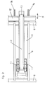
- This mining device 10 shown here has two digging and Conveyor wheels 11 on with aligned axes that are spaced apart are.
- An inclined conveyor is located between the two digging and conveyor wheels 11 12 provided, expediently a conveyor belt, with an upper discharge edge 13, over which the material to be rearranged falls during operational use.
- Mining devices this type are known, for example, from AT 386 821 B. that on the structure and operation of this mining device here in detail does not have to be received.
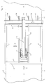
- the discharge edge 13 of the removal device 10 is adjacent, horizontally protruding cantilever arms 14 are provided, which a horizontal conveyor 15, for example a conveyor belt with reversible Drive motor, which rests on these cantilever arms 14 in the direction of arrow 5 is displaceable, in such a way that it is either in the drop area of the Mining device is located or outside of it.
- a horizontal conveyor 15 for example a conveyor belt with reversible Drive motor, which rests on these cantilever arms 14 in the direction of arrow 5 is displaceable, in such a way that it is either in the drop area of the Mining device is located or outside of it.
- the horizontal conveyor 15 is right next to the cross member 6 of the Crane bridge 4.
- the material falling over the chute 13 falls on it Horizontal conveyor 15 past down and builds the new rent 17.
- the horizontal conveyor 15 is moved on the cantilever arms 14, so that it reaches the discharge area below the discharge edge 13 (Fig. 3 - right position). That picked up by the digging and conveyor wheels 11 and goods that have been raised via the inclined conveyor 12 now fall onto the horizontal conveyor 15 and can be carried out laterally.
- the drive motor of this horizontal conveyor 15 is expediently reversible, so that the horizontal conveyor 15 can promote in two directions, which is indicated here by the arrow 18 is.
- decomposable material can be used by anyone Place of the composting field 1 are carried out laterally without it requires a complex and time-consuming shifting.
- the invention is not limited to the schematically shown mining device 10. It is possible, constructive other dismantling devices in the manner according to the invention to design. The device as such is expediently program-controlled operated.
Landscapes
- Chemical & Material Sciences (AREA)
- Chemical Kinetics & Catalysis (AREA)
- Life Sciences & Earth Sciences (AREA)
- Engineering & Computer Science (AREA)
- Biochemistry (AREA)
- Biotechnology (AREA)
- Health & Medical Sciences (AREA)
- General Chemical & Material Sciences (AREA)
- Microbiology (AREA)
- Molecular Biology (AREA)
- Organic Chemistry (AREA)
- Fertilizers (AREA)
- Processing Of Solid Wastes (AREA)
Abstract
Description
- Fig. 1
- eine Draufsicht auf ein Kompostierfeld und die hier eingesetzte Abbauvorrichtung;
- Fig. 2
- eine Draufsicht auf die Abbauvorrichtung in einem gegenüber Fig. 1 vergrößerten Maßstab;
- Fig. 3
- eine Seitensicht der Abbauvorrichtung nach Fig. 2.
- 1
- Kompostierfeld
- 2
- strichpunktierte Linie
- 3
- strichpunktierte Linie
- 4
- Kranbrücke
- 5
- Pfeil
- 6
- Längsträger
- 7
- Querträger
- 8
- Laufwagen
- 9
- Pfeil
- 10
- Abbauvorrichtung
- 11
- Grab- und Förderrad
- 12
- Schrägförderer
- 13
- Abwurfkante
- 14
- Kragarm
- 15
- Horizontalförderer - Fördereinrichtung
- 16
- Altmiete
- 17
- Neumiete
- 18
- Pfeil
Claims (3)
- Einrichtung zum Umsetzen von auf einem Kompostierfeld (1) gelagertem, verrottbarem Gut zur Kompostierung mit einer längs und quer zum Kompostierfeld (1) verfahrbaren, das umzusetzende Gut aufnehmenden und zumindest in Längsrichtung des Kompostierfeldes (1) transportierenden Abbauvorrichtung (10) mit einer Abwurfkante (13) und die Abbauvorrichtung (10) an einem Laufwagen (8) gelagert ist, der seinerseits entlang einer das Kompostierfeld (1) überspannenden Kranbrücke (4) verfahrbar ist und zum seitlichen Austrag des Gutes aus dem Kompostierfeld (1) mindestens eine sich über die Breite des Kompostierfeldes (1) und im wesentlichen parallel zur Kranbrücke (4) erstreckende Fördereinrichtung (15) mit vorzugsweise reversierbarer Förderrichtung, insbesondere ein Förderband (15) vorgesehen ist und diese Fördereinrichtung (15) unterhalb der Abwurfkante (13) der Abbauvorrichtung (10) liegt, dadurch gekennzeichnet, daß die Fördereinrichtung (15) an der Kranbrücke (4) gelagert und gegenüber der Kranbrücke (4) und rechtwinkelig zu deren Längserstreckung in den Abwurfbereich des Gutes und aus diesem Abwurfbereich verschiebbar ist.
- Einrichtung nach Anspruch 1, dadurch gekennzeichnet, daß an der Kranbrücke (4) auf der der Abwurfkante (13) der Abbauvorrichtung (10) benachbarten Seite horizontal ausladende Kragarme (14) angeordnet sind, auf welchen die Fördereinrichtung (15) verschiebbar gelagert ist.
- Einrichtung nach Anspruch 1 oder 2, dadurch gekennzeichnet, daß der Verschiebeweg der Fördereinrichtung (15) mindestens deren Breite (C) entspricht.
Applications Claiming Priority (3)
| Application Number | Priority Date | Filing Date | Title |
|---|---|---|---|
| AT27497 | 1997-02-19 | ||
| AT0027497A AT405178B (de) | 1997-02-19 | 1997-02-19 | Einrichtung zum umsetzen von auf einem kompostierfeld gelagertem, verrottbarem gut |
| AT274/97 | 1997-02-19 |
Publications (3)
| Publication Number | Publication Date |
|---|---|
| EP0860408A2 true EP0860408A2 (de) | 1998-08-26 |
| EP0860408A3 EP0860408A3 (de) | 1999-04-21 |
| EP0860408B1 EP0860408B1 (de) | 2002-01-02 |
Family
ID=3486198
Family Applications (1)
| Application Number | Title | Priority Date | Filing Date |
|---|---|---|---|
| EP19980101731 Expired - Lifetime EP0860408B1 (de) | 1997-02-19 | 1998-01-30 | Einrichtung zum Umsetzen von auf einem Kompostierfeld gelagertem, verrottbarem Gut |
Country Status (3)
| Country | Link |
|---|---|
| EP (1) | EP0860408B1 (de) |
| AT (1) | AT405178B (de) |
| DE (1) | DE59802776D1 (de) |
Families Citing this family (1)
| Publication number | Priority date | Publication date | Assignee | Title |
|---|---|---|---|---|
| AT410544B (de) * | 1998-04-09 | 2003-05-26 | Vkw Vogel & Mueller Gmbh | Einrichtung zum umsetzen von auf einem kompostierfeld gelagertem, verrottbarem gut |
Family Cites Families (6)
| Publication number | Priority date | Publication date | Assignee | Title |
|---|---|---|---|---|
| ZA743720B (en) * | 1973-07-11 | 1975-08-27 | Ohio Feed Lot | Process for aerobic thermophilic decomposition of organic waste |
| AT386821B (de) * | 1985-06-14 | 1988-10-25 | Vogel Werner Ing | Einrichtung zum umsetzen von muell auf einem kompostierfeld |
| IT1216326B (it) * | 1986-12-19 | 1990-02-22 | Francesco Ferrero | Carroponte attrezzato per il deposito rivoltamento ed evacuazione di cumuli durante il procedimento di trasformazione aerobica accelerata di miscele di rifiuti solidi urbani opportunamente trattati ed additti vati e relativo metodo di trattamento dei cumuli per quote giornaliere di prodotto |
| ES2027614T3 (es) * | 1989-03-28 | 1994-01-01 | Buehler Ag Geb | Instalacion de residuos fermentados para la produccion de compost de diferentes grados de madurez. |
| DE19508616C1 (de) * | 1995-03-10 | 1995-11-09 | Noell Abfall & Energietech | Kompostieranlage zur mechanisch-biologischen Restabfall- und Biomüllbehandlung |
| DE19510225C1 (de) * | 1995-03-23 | 1996-01-04 | Noell Abfall & Energietech | Vorrichtung zum Umsetzen von insbesondere Kompostmieten |
-
1997
- 1997-02-19 AT AT0027497A patent/AT405178B/de not_active IP Right Cessation
-
1998
- 1998-01-30 EP EP19980101731 patent/EP0860408B1/de not_active Expired - Lifetime
- 1998-01-30 DE DE59802776T patent/DE59802776D1/de not_active Expired - Fee Related
Also Published As
| Publication number | Publication date |
|---|---|
| DE59802776D1 (de) | 2002-02-28 |
| ATA27497A (de) | 1998-10-15 |
| EP0860408B1 (de) | 2002-01-02 |
| EP0860408A3 (de) | 1999-04-21 |
| AT405178B (de) | 1999-06-25 |
Similar Documents
| Publication | Publication Date | Title |
|---|---|---|
| EP0952102B1 (de) | Vorrichtung zur Übergabe von Stückgut, insbesondere von Werkstückträgern, Werkstücken, Behältern oder Paletten | |
| WO2006097253A1 (de) | Fördereinrichtung | |
| EP0664262A1 (de) | Kipp-Förderelement für einen Stückgutförderer (Sorter) | |
| CH650473A5 (de) | Umlenkvorrichtung fuer transportbahnen. | |
| EP0860408B1 (de) | Einrichtung zum Umsetzen von auf einem Kompostierfeld gelagertem, verrottbarem Gut | |
| DE2425452C3 (de) | Vorrichtung zur Übergabe von Gegenständen | |
| DE19510225C1 (de) | Vorrichtung zum Umsetzen von insbesondere Kompostmieten | |
| DE69307550T2 (de) | Vorrichtung für vorübergehende lagerung von schüttgütern | |
| EP0010548B1 (de) | In einer Horizontalebene dreh- und arretierbare Umlenkvorrichtung | |
| DE10044048B4 (de) | Vorrichtung zum Überführen von Transportmitteln | |
| EP0254953A1 (de) | Silo für Schüttgut | |
| DE2802188C3 (de) | Vorrichtung zum Ordnen von schweren metallischen Werkstücken | |
| DE60028222T2 (de) | Vorrichtung zum sortieren von schnittholz | |
| EP0860409B1 (de) | Einrichtung zum Umsetzen von auf einem Kompostierfeld gelagertem, verrottbarem Gut | |
| EP0222063A2 (de) | Vorrichtung zum Austrag von Schüttgut aus einer Halde | |
| AT410544B (de) | Einrichtung zum umsetzen von auf einem kompostierfeld gelagertem, verrottbarem gut | |
| DE3718208A1 (de) | Foerdereinrichtung | |
| DE2822732C2 (de) | ||
| DE3524778C1 (de) | Vorrichtung zum Aufnehmen und Abfoerdern von in Haufwerken gelagerten Feldfruechten | |
| DD257812A1 (de) | Verfahren und gurtbandfoerderer zum schuettguttransport in einer bandlinie | |
| DE1245859B (de) | Vorrichtung zum Mischen von Schuettmassen beim Aufnehmen aus Mischbetten | |
| DE2446873A1 (de) | Plattenband zum laengstransport von stueckguetern und zu deren seitlicher aufnahme an beliebiger stelle | |
| DE2709778A1 (de) | Vorrichtung zum transport von materialien in granulat- oder pulverform | |
| DD281794A5 (de) | Foerdergutaufgabestelle | |
| DE2314528A1 (de) | Vorrichtung zur regulierung der schichthoehe eines foerdergutstromes auf einem bandfoerderer |
Legal Events
| Date | Code | Title | Description |
|---|---|---|---|
| PUAI | Public reference made under article 153(3) epc to a published international application that has entered the european phase |
Free format text: ORIGINAL CODE: 0009012 |
|
| AK | Designated contracting states |
Kind code of ref document: A2 Designated state(s): DE ES GB IT |
|
| AX | Request for extension of the european patent |
Free format text: AL;LT;LV;MK;RO;SI |
|
| PUAL | Search report despatched |
Free format text: ORIGINAL CODE: 0009013 |
|
| AK | Designated contracting states |
Kind code of ref document: A3 Designated state(s): AT BE CH DE DK ES FI FR GB GR IE IT LI LU MC NL PT SE |
|
| AX | Request for extension of the european patent |
Free format text: AL;LT;LV;MK;RO;SI |
|
| RAP1 | Party data changed (applicant data changed or rights of an application transferred) |
Owner name: VKW-VOGEL & MUELLER GMBH |
|
| RIN1 | Information on inventor provided before grant (corrected) |
Inventor name: VKW-VOGEL & MUELLER GMBH |
|
| 17P | Request for examination filed |
Effective date: 19991006 |
|
| AKX | Designation fees paid |
Free format text: DE ES GB IT |
|
| 17Q | First examination report despatched |
Effective date: 20000114 |
|
| GRAG | Despatch of communication of intention to grant |
Free format text: ORIGINAL CODE: EPIDOS AGRA |
|
| GRAG | Despatch of communication of intention to grant |
Free format text: ORIGINAL CODE: EPIDOS AGRA |
|
| GRAH | Despatch of communication of intention to grant a patent |
Free format text: ORIGINAL CODE: EPIDOS IGRA |
|
| GRAH | Despatch of communication of intention to grant a patent |
Free format text: ORIGINAL CODE: EPIDOS IGRA |
|
| RAP1 | Party data changed (applicant data changed or rights of an application transferred) |
Owner name: VKW ANLAGENBAU UND UMWELTTECHNIK GMBH |
|
| RIN1 | Information on inventor provided before grant (corrected) |
Inventor name: VKW ANLAGENBAU UND UMWELTTECHNIK GMBH |
|
| GRAA | (expected) grant |
Free format text: ORIGINAL CODE: 0009210 |
|
| REG | Reference to a national code |
Ref country code: GB Ref legal event code: IF02 |
|
| AK | Designated contracting states |
Kind code of ref document: B1 Designated state(s): DE ES GB IT |
|
| PG25 | Lapsed in a contracting state [announced via postgrant information from national office to epo] |
Ref country code: IT Free format text: LAPSE BECAUSE OF FAILURE TO SUBMIT A TRANSLATION OF THE DESCRIPTION OR TO PAY THE FEE WITHIN THE PRESCRIBED TIME-LIMIT;WARNING: LAPSES OF ITALIAN PATENTS WITH EFFECTIVE DATE BEFORE 2007 MAY HAVE OCCURRED AT ANY TIME BEFORE 2007. THE CORRECT EFFECTIVE DATE MAY BE DIFFERENT FROM THE ONE RECORDED. Effective date: 20020102 Ref country code: GB Free format text: LAPSE BECAUSE OF FAILURE TO SUBMIT A TRANSLATION OF THE DESCRIPTION OR TO PAY THE FEE WITHIN THE PRESCRIBED TIME-LIMIT Effective date: 20020102 |
|
| REF | Corresponds to: |
Ref document number: 59802776 Country of ref document: DE Date of ref document: 20020228 |
|
| PG25 | Lapsed in a contracting state [announced via postgrant information from national office to epo] |
Ref country code: ES Free format text: LAPSE BECAUSE OF FAILURE TO SUBMIT A TRANSLATION OF THE DESCRIPTION OR TO PAY THE FEE WITHIN THE PRESCRIBED TIME-LIMIT Effective date: 20020730 |
|
| PLBE | No opposition filed within time limit |
Free format text: ORIGINAL CODE: 0009261 |
|
| STAA | Information on the status of an ep patent application or granted ep patent |
Free format text: STATUS: NO OPPOSITION FILED WITHIN TIME LIMIT |
|
| 26N | No opposition filed | ||
| PGFP | Annual fee paid to national office [announced via postgrant information from national office to epo] |
Ref country code: DE Payment date: 20050321 Year of fee payment: 8 |
|
| PG25 | Lapsed in a contracting state [announced via postgrant information from national office to epo] |
Ref country code: DE Free format text: LAPSE BECAUSE OF NON-PAYMENT OF DUE FEES Effective date: 20060801 |