EP0860245B1 - Pressing tool - Google Patents
Pressing tool Download PDFInfo
- Publication number
- EP0860245B1 EP0860245B1 EP19980101788 EP98101788A EP0860245B1 EP 0860245 B1 EP0860245 B1 EP 0860245B1 EP 19980101788 EP19980101788 EP 19980101788 EP 98101788 A EP98101788 A EP 98101788A EP 0860245 B1 EP0860245 B1 EP 0860245B1
- Authority
- EP
- European Patent Office
- Prior art keywords
- pressing
- pressing tool
- movable
- tool according
- jaws
- Prior art date
- Legal status (The legal status is an assumption and is not a legal conclusion. Google has not performed a legal analysis and makes no representation as to the accuracy of the status listed.)
- Expired - Lifetime
Links
Images


Classifications
-
- H—ELECTRICITY
- H01—ELECTRIC ELEMENTS
- H01R—ELECTRICALLY-CONDUCTIVE CONNECTIONS; STRUCTURAL ASSOCIATIONS OF A PLURALITY OF MUTUALLY-INSULATED ELECTRICAL CONNECTING ELEMENTS; COUPLING DEVICES; CURRENT COLLECTORS
- H01R43/00—Apparatus or processes specially adapted for manufacturing, assembling, maintaining, or repairing of line connectors or current collectors or for joining electric conductors
- H01R43/04—Apparatus or processes specially adapted for manufacturing, assembling, maintaining, or repairing of line connectors or current collectors or for joining electric conductors for forming connections by deformation, e.g. crimping tool
- H01R43/042—Hand tools for crimping
- H01R43/0427—Hand tools for crimping fluid actuated hand crimping tools
-
- B—PERFORMING OPERATIONS; TRANSPORTING
- B25—HAND TOOLS; PORTABLE POWER-DRIVEN TOOLS; MANIPULATORS
- B25B—TOOLS OR BENCH DEVICES NOT OTHERWISE PROVIDED FOR, FOR FASTENING, CONNECTING, DISENGAGING OR HOLDING
- B25B27/00—Hand tools, specially adapted for fitting together or separating parts or objects whether or not involving some deformation, not otherwise provided for
- B25B27/02—Hand tools, specially adapted for fitting together or separating parts or objects whether or not involving some deformation, not otherwise provided for for connecting objects by press fit or detaching same
- B25B27/10—Hand tools, specially adapted for fitting together or separating parts or objects whether or not involving some deformation, not otherwise provided for for connecting objects by press fit or detaching same inserting fittings into hoses
Definitions
- the invention relates to a pressing device for connecting tubular workpieces, for example a pipe with a press fitting, with at least two press jaws surrounding a pressing chamber, of which at least two are movable relative to each other so that they are placed on the workpiece in an open position and for the pressing operation by means of a drive motor are movable into a closed position, wherein the or at least two of the movable cheek plates - directly or indirectly - are coupled such that upon actuation of a movable cheek and the other (n) movable cheek plate (n ) is moved in the same direction or be, and wherein the pressing device has on its housing a grip portion for a holding hand, which allows a holding of the pressing device.
- sleeve-shaped press fittings which are made of plastic or metal.
- the press fitting is slid over the pipe ends to make a pipe joint and then radially compressed in the overlapping areas, with both the press fitting and the pipe being plastically deformed become.
- Such pipe connections and the associated press fittings are known, for example, from EP-B 0 361 630.
- the pressing of the press fitting and the tube is done by means of pressing devices, as they are known in various embodiments, for example in DE-C 21 36 782, DE-A-34 23 283 and EP-A-0 451 806.
- the pressing devices consist of a pressing tool and a drive for the pressing tool.
- the pressing tool has at least two, in some cases also more cheek plates, of which at least two cheek plates are movable relative to each other. You can be moved in this way in an open position in which an attachment of the pressing device to the press fitting is possible. Subsequently, the cheek plates can be moved together with the help of the drive to a closed position.
- a drive hydraulic piston is often provided, which can be acted upon by a hand-operated or electric motor driven pump with hydraulic pressure. An electric drive is known.
- FR 2 528 750 A and GB 1 179 929 A presses are disclosed in which two movable cheek plates are coupled so that upon actuation of a cheek plate and the other movable cheek plate is moved in the same direction. Due to this coupling, the actuation of a single cheek plate to move both movable cheek plates either in the direction of the open position or in the direction of the closed position, which makes the operation of the pressing device easier and safer. Nevertheless, two hands are required to open the cheek plates.
- the invention is therefore based on the object to design a pressing device of the type mentioned so that the operation is simple and secure.
- a pressing device according to claim 1, wherein the handle portion is provided so that one of the movable cheek plates by means of the holding hand on the handle portion in the direction of the open position is movable, and that the pressing device comprises a switch for switching on the drive, the Griff Silvert is assigned such that it is actuated by a finger or thumb of the holding hand. Due to this assignment of the intended grip area, at least one of the movable press jaws and the switch for switching on the drive, the opening of the press jaws and the switching on can take place with one hand, which simplifies the handling of the pressing device. In addition, the handling is also safer, because the other hand is free to cling to ladders or the like, for example.
- the coupling of the cheek plates can be done in different ways.
- a coupling rod is used for this purpose, which is hinged to the cheek plates or associated parts such that the movement of a cheek plate is transferred to the other cheek so that both in the direction of either the open or the closed position and thus to move in the same direction, albeit usually in the opposite direction.
- the same effect can be achieved via a coupling friction or a coupling toothing.
- a kind of coupling toothing consists, for example, that the or at least two adjacent movable cheek plates have two opposite recesses in which a coupling element engages such that upon actuation of a Preßbakke and the other cheek plate is moved in the same direction.
- the coupled cheek plates are spring-loaded in the closing direction, so that they close themselves after applying the pressing device to the press fitting by itself. This also facilitates the handling of the pressing device.
- the cheek plates have in known manner drive lever or are connected to it, which can be acted upon by a drive in the closing direction, they should end adjacent to this handle area, so that they can be moved over the cheek plates in the open position.
- the above-described training allows a particularly convenient one-handed operation of the pressing device. The other hand is free either to hold the pipeline or to secure himself to a ladder or scaffolding.
- the handle portion is associated with an actuating lever, via which one of the movable cheek plates - possibly via the drive lever - in the direction of the open position can be acted upon.
- a blocking device for non-positive or positive blocking of at least one of the coupled cheek plates is provided in the open position.
- Such a blocking device is particularly useful if - as provided above - the coupled cheek plates are spring-loaded in the closing direction. After opening the cheek plates, it is then no longer necessary to hold the cheek plates in this position. It is understood that the blocking for the closing of the cheek plates must be canceled again.
- the blocking device can be designed in various ways. So there is the possibility to train them as magnets. If the movable cheek plates - as known per se - have drive lever or articulated with them, they can be provided with magnets which bear against each other in the open position of the cheek plates. Alternatively, the blocking device may also be designed as a movable blocking element, which is movable in the open position of the cheek plates in a blocking position. This may be locking elements, etc. In this case, the blocking element should be spring-loaded in the direction of the blocking position, so that it jumps on reaching the open position by itself in the blocking position.
- the pressing device has a gripping area for gripping the pressing device with one hand and the blocking element is assigned to the grip area such that it can be actuated by this hand.
- a movable sensor protrudes, which is coupled to the blocking device such that it causes a release of the Blokkier immunity when attaching the pressing device to the workpiece. In this way, an influence of the blocking device by hand is not necessary.
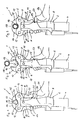
- the pressing device 1 shown in Figures 1 to 3 essentially consists of a drive 2 and a pressing tool 3.
- the drive 2 has an electric drive motor 4, which acts via a gear 5 on a movable in the longitudinal direction of the pressing device 1, hidden drive stamp, such as this results, for example, from DE-U-295 02 032.6.
- the drive 2 runs in the direction of the pressing tool 3 in a holding fork 6, which is arranged by a front fork piece 7 and at a distance behind it and therefore not visible second fork piece is formed. In the space between the two fork pieces 7 of the drive stamp is retractable.
- the fork pieces 7 are connected to each other via a bearing pin 8.
- This bearing pin 8 passes through two T-shaped bearing plates 9, of which only the front bearing plate lying in the views to see 9, while the rear, identical bearing plate is covered by the front bearing plate 9.
- the bearing plates 9 are each directly adjacent to the respective adjacent fork piece 7 and have a distance from each other.
- two mirror-formed press jaws 10, 11 are arranged and mounted on the bearing plates 9 pivotally mounted in the plane of the drawing via bearing pins 12, 13.
- the unit of bearing plates 9 and cheek plates 10, 11 with bearing pins 12, 13 form the pressing tool 3 and are separable as a whole by removing the bearing pin 8 of the drive 2. In this way can be attached to the drive 2 different sizes of pressing tools 3.
- the cheek plates 10, 11 have above the bearing pin 12, 13 jaw arms 14, 15, in the opposite jaw recesses 16, 17 are formed. Between the Preßbacken 10, 11 is a third cheek plate 19, which is fixed between the bearing plates 9, that is held immovable. Your jaw recess 20 completes the jaw recesses 16, 17 in such a way that in the closed state of the Preßtechnikmaschinees 3 a closed baling chamber 21 is formed.
- Figure 1 shows the position of the pressing device 1 before startup.
- the movable Preßbacken 10, 11 are due to a spring bias in the closed position.
- a hand 26 surrounds the housing of the drive 2 at a location provided immediately adjacent the free ends of the drive lever 22, 23, in such a way that the thumb 27 of the hand 26 can be placed on the outside of the right drive lever 23, without that thereby the handle is lost to the housing of the drive 2.
- the pressing device 1 can be attached to a pipe joint 28 transverse to the tube axis, the pressing chamber 21 is thereby opened at the top, that the right drive lever 23 by means of the thumb 27 is pivoted inwardly, ie clockwise. Due to a kinematic connection, not shown here, shown in more detail in the other figures The two cheek plates 10, 11, the pivoting movement of the right cheek plate 11 is transferred to the left cheek plate 10 such that they are pivoted in the opening direction, ie in the opposite direction and thus counterclockwise. In this way, the symmetrical open position of the cheek plates 10, 11 shown in Figure 2 is achieved. Between the free ends of the jaw arms 14, 15 results in a mouth-like opening, which is slightly larger than the diameter of the pipe joint 28, so that the pressing device 1 can be moved over this.
- a bearing pin 34 is pivotally mounted.
- the actuating lever 33 thus lies in the grip region of the fingers of the hand 26 and is surrounded by these when holding the pressing device 1 on the outside.
- At the upper end of the actuating lever 33 is located on the outside of the left drive lever 22 at.
- the embodiment according to FIGS. 6 and 7 has a blocking device 35 which is intended to hold the press jaws 10, 11 in the open position (FIG. 7) against the action of the spring bias acting in the closing direction.
- the blocking device 35 has a blocking ring 36, which surrounds the retaining fork 6 and is displaceably guided on it in the longitudinal direction of the pressing device 1.
- the blocking ring 36 is supported by compression springs 37, 38 on the retaining fork 6, so that it bears against the drive levers 22, 23 on the upper side under pretension.
- the blocking device 35 has two magnets 39, 40, which are embedded in the drive surfaces 24, 25 opposite one another.
- the magnets come 39, 40 for mutual contact and keep the Preßbakken 10, 11 in this position.
- the cheek plate 19 is penetrated by an opening rod 41 which is biased by a compression spring 42 in the direction of the pressing chamber 21 and axially movable.
- the opening rod 41 protrudes a piece over the jaw recess 20 into the baling chamber 21.
- At the lower end of the opening rod 41 is formed so that it projects into the downwardly tapered space between the two drive surfaces 24, 25 and fills it.
- the opening rod 41 When attaching the pressing device in the position shown in Figure 9 at a pipe joint, the opening rod 41 is moved through the pipe joint in the direction of the magnets 39, 40 and thereby spreads the drive lever 22, 23 a piece apart. The magnets 39, 40 are released, and the cheek plates 10, 11 move to the closed position. After removal of the pressing device 1 of the pipe joint, the opening rod 41 is pressed by the compression spring 42 back into the position shown in Figure 9.
- Figures 10 and 11 show the pressing tool 3 after removal of the drive 2, wherein here the front bearing plate 9 is not shown. In this way, the view is released on two friction wheels 43, 44 which are freely rotatable in.der cheek plate 19 are mounted side by side and abut each other with their peripheral surfaces.
- the movable press jaws 10, 11 have transfer surfaces 45, 46, which are formed as circular arc sections which extend concentrically to the bearing pins 12, 13. They lie on the peripheral surfaces of the respective adjacent friction wheel 43, 44th at.
- the pressing tool 47 shown in Figures 12 and 13 is also shown without drive. It has two mirror-image forming cheek plates 48, 49, which are arranged between two bearing plates 50, of which the front bearing plate lying in the view - as in the previous embodiments - is omitted. On the bearing plates 50, the cheek plates 48, 49 are pivotally mounted on bearing pins 51, 52. can be connected via a further bearing pin 53 - similar to the embodiments of Figures 1 to 9 - a drive.
- the Preßbacken 48, 49 have above the bearing pin 51, 52 jaw arms 54, 55, in the opposite jaw recesses 56, 57 are formed. In contrast to the embodiments described so far, a third cheek plate is missing. Below the bearing pins 51, 52 run the Preßbakken 48, 49 in drive lever 58, 59, the opposite drive surfaces 60, 61 form. In the gap between the drive surfaces 60, 61 can - as in the embodiments described above - the drive stem of a drive motor are retracted.
- the Preßbacken 48, 49 have slightly below the plane of the bearing pin 51, 52 opposite, approximately semicircular recesses 62, 63, into which a transmission pin 64 is inserted circular cross-section. In the axial direction of the transmission pin 64 is bordered by the two bearing plates 50 so that it can not fall out.
- the recesses 62, 63 adjoin one another on the top side, while a free space 65 exists on the bottom side.
- the free space 65 is shaped so that a pivoting of the cheek plates 48, 49 from the closed position ( Figure 12) in the open position ( Figure 13) is possible.
Landscapes
- Engineering & Computer Science (AREA)
- Manufacturing & Machinery (AREA)
- Mechanical Engineering (AREA)
- Manipulator (AREA)
- Apparatuses For Bulk Treatment Of Fruits And Vegetables And Apparatuses For Preparing Feeds (AREA)
- Encapsulation Of And Coatings For Semiconductor Or Solid State Devices (AREA)
- Confectionery (AREA)
- Hand Tools For Fitting Together And Separating, Or Other Hand Tools (AREA)
- Press Drives And Press Lines (AREA)
- Shaping Of Tube Ends By Bending Or Straightening (AREA)
Description
Die Erfindung betrifft ein Preßgerät zum Verbinden von rohrförmigen Werkstücken, beispielsweise eines Rohrs mit einem Preßfitting, mit wenigstens zwei einen Preßraum umgebenden Preßbacken, die bzw. von denen wenigstens zwei derart relativ zueinander beweglich sind, daß sie zum Aufsetzen auf das Werkstück in eine Offenstellung und für den Verpreßvorgang mittels eines Antriebsmotors bis in eine Schließstellung bewegbar sind, wobei die bzw. zumindest zwei der beweglichen Preßbacken - direkt oder indirekt - derart gekoppelt sind, daß bei Betätigung einer beweglichen Preßbacke auch die andere(n) bewegliche(n) Preßbacke(n) gleichsinnig bewegt wird bzw. werden, und wobei das Preßgerät an seinem Gehäuse einen Griffbereich für eine Haltehand aufweist, der ein Halten des Preßgerätes zuläßt.The invention relates to a pressing device for connecting tubular workpieces, for example a pipe with a press fitting, with at least two press jaws surrounding a pressing chamber, of which at least two are movable relative to each other so that they are placed on the workpiece in an open position and for the pressing operation by means of a drive motor are movable into a closed position, wherein the or at least two of the movable cheek plates - directly or indirectly - are coupled such that upon actuation of a movable cheek and the other (n) movable cheek plate (n ) is moved in the same direction or be, and wherein the pressing device has on its housing a grip portion for a holding hand, which allows a holding of the pressing device.
Zum Verbinden von Rohren ist es bekannt, hülsenförmige Preßfittings zu verwenden, die aus Kunststoff oder Metall bestehen. Das Preßfitting wird zwecks Herstellung einer Rohrverbindung über die Rohrenden geschoben und dann in den Überlappungsbereichen radial zusammengepreßt, wobei sowohl das Preßfitting als auch das Rohr plastisch verformt werden. Solche Rohrverbindungen und die zugehörigen Preßfittings sind beispielsweise aus der EP-B 0 361 630 bekannt.For connecting pipes, it is known to use sleeve-shaped press fittings, which are made of plastic or metal. The press fitting is slid over the pipe ends to make a pipe joint and then radially compressed in the overlapping areas, with both the press fitting and the pipe being plastically deformed become. Such pipe connections and the associated press fittings are known, for example, from EP-B 0 361 630.
Die Verpressung des Preßfittings und des Rohrs geschieht mit Hilfe von Preßgeräten, wie sie in verschiedenen Ausführungen beispielsweise in der DE-C 21 36 782, DE-A-34 23 283 und EP-A-0 451 806 bekannt sind. Die Preßgeräte bestehen aus einem Preßwerkzeug und einem Antrieb für das Preßwerkzeug.The pressing of the press fitting and the tube is done by means of pressing devices, as they are known in various embodiments, for example in DE-C 21 36 782, DE-A-34 23 283 and EP-A-0 451 806. The pressing devices consist of a pressing tool and a drive for the pressing tool.
Das Preßwerkzeug hat zumindest zwei, teilweise auch mehr Preßbacken, die bzw. von denen zumindest zwei Preßbacken relativ zueinander beweglich sind. Sie können auf diese Weise in einer Offenstellung bewegt werden, in der ein Ansetzen des Preßgerätes an dem Preßfitting möglich ist. Anschließend können die Preßbacken mit Hilfe des Antriebes bis in eine Schließstellung zusammengefahren werden. Als Antrieb ist vielfach ein Hydraulikkolben vorgesehen, der über eine handbetriebene oder elektromotorisch angetriebene Pumpe mit Hydraulikdruck beaufschlagt werden kann. Auch ein elektrischer Antrieb ist bekannt.The pressing tool has at least two, in some cases also more cheek plates, of which at least two cheek plates are movable relative to each other. You can be moved in this way in an open position in which an attachment of the pressing device to the press fitting is possible. Subsequently, the cheek plates can be moved together with the help of the drive to a closed position. As a drive hydraulic piston is often provided, which can be acted upon by a hand-operated or electric motor driven pump with hydraulic pressure. An electric drive is known.
Bei der Handhabung wird das Preßgerät mit einer Hand in einem Griffbereich umfaßt, der hinten außerhalb des Schwerpunkts des Preßgerätes liegt. Für das Öffnen der beweglichen Preßbacken ist die andere Hand notwendig, so daß beide Hände für das Ansetzen des Preßgerätes an einer Rohrleitung belegt sind. Dies erschwert das Ansetzen des Preßgerätes an dem vorgesehenen Ort, zumal die Rohre in der Regel nicht fixiert sind und sogar teilweise lediglich an Ketten hängen. Soweit Rohrleitungen unter einer Raumdecke verlegt werden müssen, arbeiten die Bedienungspersonen auf Leitern. Da die Hände durch Bedienung des Preßgerätes belegt sind, besteht erhöhte Unfallgefahr.In handling the pressing device is covered with a hand in a grip area, which lies behind the center of gravity of the pressing device at the rear. For the opening of the movable cheek plates, the other hand is necessary, so that both hands are busy for the attachment of the pressing device to a pipeline. This complicates the attachment of the pressing device at the intended location, especially as the pipes in usually are not fixed and even partially hang only on chains. As far as piping must be laid under a ceiling, the operators work on ladders. Since the hands are occupied by operation of the pressing device, there is an increased risk of accidents.
In der FR 2 528 750 A und der GB 1 179 929 A sind Preßgeräte offenbart, bei denen zwei bewegliche Preßbacken derart gekoppelt sind, daß bei Betätigung einer Preßbacke auch die andere bewegliche Preßbacke gleichsinnig bewegt wird. Aufgrund dieser Kopplung genügt die Betätigung einer einzigen Preßbacke, um beide beweglichen Preßbacken entweder in Richtung der Offenstellung oder in Richtung der Schließstellung zu bewegen, was die Bedienung des Preßgeräts vereinfacht und sicherer macht. Gleichwohl sind zum Öffnen der Preßbacken zwei Hände erforderlich.In
Der Erfindung liegt somit die Aufgabe zugrunde, ein Preßgerät der eingangs genannten Art so zu gestalten, daß die Bedienung einfach und sicherer ist.The invention is therefore based on the object to design a pressing device of the type mentioned so that the operation is simple and secure.
Diese Aufgabe wird erfindungsgemäß durch ein Preßgerät nach Anspruch 1 gelöst, wobei der Griffbereich so vorgesehen ist, daß eine der beweglichen Preßbacken mittels der Haltehand am Griffbereich in Richtung der Offenstellung bewegbar ist, und daß das Preßgerät einen Schalter zum Einschalten des Antriebs aufweist, der dem Griffbereicht derart zugeordnet ist, daß er von einem Finger oder Daumen der Haltehand betätigbar ist. Aufgrund dieser Zuordnung von bestimmungsgemäßem Griffbereich, zumindest einer der beweglichen Preßbacken und dem Schalter zum Einschalten des Antriebs kann das Öffnen der Preßbacken und das Einschalten mit einer Hand erfolgen, was die Handhabung des Preßgeräts vereinfacht. Zudem ist die Handhabung auch sicherer, weil die andere Hand frei ist, um sich beispielsweise an Leitern oder dergleichen festhalten zu können.This object is achieved by a pressing device according to claim 1, wherein the handle portion is provided so that one of the movable cheek plates by means of the holding hand on the handle portion in the direction of the open position is movable, and that the pressing device comprises a switch for switching on the drive, the Griffbereicht is assigned such that it is actuated by a finger or thumb of the holding hand. Due to this assignment of the intended grip area, at least one of the movable press jaws and the switch for switching on the drive, the opening of the press jaws and the switching on can take place with one hand, which simplifies the handling of the pressing device. In addition, the handling is also safer, because the other hand is free to cling to ladders or the like, for example.
Die Koppelung der Preßbacken kann auf verschiedene Weise geschehen. Bei einer Ausführungsform wird hierzu jeweils eine Koppelstange verwendet, die an den Preßbacken oder damit verbundenen Teilen derart angelenkt wird, daß die Bewegung der eine Preßbacke auf die andere Preßbacke derart übertragen wird, daß beide sich in Richtung entweder der Offen- oder der Schließstellung und damit gleichsinnig, wenn auch in der Regel entgegengesetzt, bewegen. Die selbe Wirkung kann über einen Koppelreibschluß oder eine Koppelverzahnung erzielt werden. Eine Art Koppelverzahnung besteht beispielsweise darin, daß die bzw. zumindest zwei benachbarte bewegliche Preßbacken zwei gegenüberliegende Ausnehmungen aufweisen, in die ein Koppelelement dergestalt einfaßt, daß bei Betätigung der einen Preßbakke auch die andere Preßbacke gleichsinnig bewegt wird.The coupling of the cheek plates can be done in different ways. In one embodiment, a coupling rod is used for this purpose, which is hinged to the cheek plates or associated parts such that the movement of a cheek plate is transferred to the other cheek so that both in the direction of either the open or the closed position and thus to move in the same direction, albeit usually in the opposite direction. The same effect can be achieved via a coupling friction or a coupling toothing. A kind of coupling toothing consists, for example, that the or at least two adjacent movable cheek plates have two opposite recesses in which a coupling element engages such that upon actuation of a Preßbakke and the other cheek plate is moved in the same direction.
In weiterer Ausgestaltung der Erfindung ist vorgesehen, daß die gekoppelten Preßbacken in Schließrichtung federbaufschlagt sind, so daß sie sich nach Ansetzen des Preßgerätes an das Preßfitting von selbst schließen. Auch dies erleichtert die Handhabung des Preßgerätes.In a further embodiment of the invention, it is provided that the coupled cheek plates are spring-loaded in the closing direction, so that they close themselves after applying the pressing device to the press fitting by itself. This also facilitates the handling of the pressing device.
Sofern die Preßbacken in an sich bekannter Weise Antriebshebel aufweisen oder damit verbunden sind, die von einem Antrieb in Schließrichtung beaufschlagbar sind,
sollten sie benachbart zu diesem Griffbereich enden, damit über sie die Preßbacken in Offenstellung bewegt werden können. Die vorbeschriebene Ausbildung läßt eine besonders bequeme Einhandbedienung des Preßgerätes zu. Die andere Hand ist frei, entweder die Rohrleitung festzuhalten oder sich an einer Leiter oder einem Gerüst zu sichern. Alternativ dazu kann vorgesehen sein, daß dem Griffbereich ein Betätigungshebel zugeordnet ist, über den einer der beweglichen Preßbacken - ggf. über dessen Antriebshebel - in Richtung der Offenstellung beaufschlagbar ist.Provided that the cheek plates have in known manner drive lever or are connected to it, which can be acted upon by a drive in the closing direction,
they should end adjacent to this handle area, so that they can be moved over the cheek plates in the open position. The above-described training allows a particularly convenient one-handed operation of the pressing device. The other hand is free either to hold the pipeline or to secure himself to a ladder or scaffolding. Alternatively, it can be provided that the handle portion is associated with an actuating lever, via which one of the movable cheek plates - possibly via the drive lever - in the direction of the open position can be acted upon.
In weiterer Ausgestaltung der Erfindung ist vorgeschlagen, daß eine Blockiereinrichtung zum kraft- oder formschlüssigen Blockieren wenigstens einer der gekoppelten Preßbacken in Offenstellung vorgesehen ist. Eine solche Blockiereinrichtung ist insbesondere dann nützlich, wenn - wie oben vorgesehen - die gekoppelten Preßbacken in Schließrichtung federbeaufschlagt sind. Nach Öffnen der Preßbacken ist es dann nicht mehr nötig, die Preßbacken in dieser Position festzuhalten. Es versteht sich, daß die Blockierung für das Schließen der Preßbacken wieder aufhebbar sein muß.In a further embodiment of the invention it is proposed that a blocking device for non-positive or positive blocking of at least one of the coupled cheek plates is provided in the open position. Such a blocking device is particularly useful if - as provided above - the coupled cheek plates are spring-loaded in the closing direction. After opening the cheek plates, it is then no longer necessary to hold the cheek plates in this position. It is understood that the blocking for the closing of the cheek plates must be canceled again.
Die Blockiereinrichtung kann auf verschiedene Weise ausgebildet sein. So besteht die Möglichkeit, sie als Magnete auszubilden. Sofern die beweglichen Preßbacken - wie an sich bekannt - Antriebshebel aufweisen oder mit ihnen gelenkig verbunden sind, können diese mit Magneten versehen sein, welche in Offenstellung der Preßbacken aneinander anliegen. Alternativ dazu kann die Blockiereinrichtung auch als bewegliches Blockierelement ausgebildet sein, welches in Offenstellung der Preßbacken in eine Blockierstellung bewegbar ist. Hierbei kann es sich um Rastelemente etc. handeln. Dabei sollte das Blockierelement in Richtung der Blockierstellung federbelastet sein, damit es bei Erreichen der Offenstellung von selbst in die Blockierstellung springt.The blocking device can be designed in various ways. So there is the possibility to train them as magnets. If the movable cheek plates - as known per se - have drive lever or articulated with them, they can be provided with magnets which bear against each other in the open position of the cheek plates. Alternatively, the blocking device may also be designed as a movable blocking element, which is movable in the open position of the cheek plates in a blocking position. This may be locking elements, etc. In this case, the blocking element should be spring-loaded in the direction of the blocking position, so that it jumps on reaching the open position by itself in the blocking position.
Nach einem weiteren Merkmal der Erfindung ist vorgesehen, daß das Preßgerät einen Griffbereich zum Greifen des Preßgerätes mit einer Hand aufweist und das Blockierelement dem Griffbereich derart zugeordnet ist, daß es von dieser Hand betätigbar ist. Alternativ dazu kann vorgesehen sein, daß in den Preßraum ein beweglicher Fühler hineinragt, der derart mit der Blockiereinrichtung gekoppelt ist, daß er beim Ansetzen des Preßgeräts an dem Werkstück ein Lösen der Blokkiereinrichtung bewirkt. Auf diese Weise ist eine Beeinflussung der Blockiereinrichtung von Hand nicht notwendig.According to a further feature of the invention it is provided that the pressing device has a gripping area for gripping the pressing device with one hand and the blocking element is assigned to the grip area such that it can be actuated by this hand. Alternatively, it can be provided that in the compression chamber, a movable sensor protrudes, which is coupled to the blocking device such that it causes a release of the Blokkiereinrichtung when attaching the pressing device to the workpiece. In this way, an influence of the blocking device by hand is not necessary.
In der Zeichnung ist die Erfindung anhand von Ausführungsbeispielen näher veranschaulicht. Es zeigen:
- Figur 1
- die Seitenansicht eines erfindungsgemäßen Preßgerätes in Schließstellung;
Figur 2- das Preßgerät gemäß Figur 1 in Offenstellung vor dem Ansetzen an einer Rohrverbindung;
Figur 3- das Preßgerät gemäß den Figuren 1 und 2 nach dem Ansetzen an der Rohrverbindung;
Figur 4- die teilweise Seitenansicht eines zweiten erfindungsgemäßen Preßgerätes in Schließstellung;
Figur 5- das Preßgerät gemäß
Figur 4 in Offenstellung; Figur 6- die teilweise Seitenansicht eines dritten erfindungsgemäßen Preßgerätes in Schließstellung;
Figur 7- das Preßgerät gemäß
Figur 6 in Offenstellung; Figur 8- die teilweise Seitenansicht eines vierten erfindungsgemäßen Preßgerätes in Schließstellung;
Figur 9- das Preßgerät gemäß
Figur 8 in Offenstellung; Figur 10- die Seitenansicht eines Preßwerkzeuges eines fünften erfindungsgemäßen Preßgerätes in Schließstellung;
Figur 11- das
Preßwerkzeug gemäß Figur 10 in Offenstellung; Figur 12- die Seitenansicht eines Preßwerkzeuges eines sechsten erfindungsgemäßen Preßgerätes in Schließstellung mit herausgezogener Ausschnittsvergrößerung der Koppelung und
Figur 13- das
Preßwerkzeug gemäß Figur 12 in Offenstellung mit herausgezogener Ausschnittsvergrößerung der Koppelung.
- FIG. 1
- the side view of a pressing device according to the invention in the closed position;
- FIG. 2
- the pressing device according to Figure 1 in the open position prior to attachment to a pipe joint;
- FIG. 3
- the pressing device according to Figures 1 and 2 after attachment to the pipe joint;
- FIG. 4
- the partial side view of a second pressing device according to the invention in the closed position;
- FIG. 5
- the pressing device according to Figure 4 in the open position;
- FIG. 6
- the partial side view of a third pressing device according to the invention in the closed position;
- FIG. 7
- the pressing device according to Figure 6 in the open position;
- FIG. 8
- the partial side view of a fourth pressing device according to the invention in the closed position;
- FIG. 9
- the pressing device according to Figure 8 in the open position;
- FIG. 10
- the side view of a pressing tool of a fifth pressing device according to the invention in the closed position;
- FIG. 11
- the pressing tool of Figure 10 in the open position;
- FIG. 12
- the side view of a pressing tool of a sixth pressing device according to the invention in the closed position with extracted detail enlargement of the coupling and
- FIG. 13
- the pressing tool of Figure 12 in the open position with extracted detail enlargement of the coupling.
Das in den Figuren 1 bis 3 dargestellte Preßgerät 1 besteht im wesentlichen aus einem Antrieb 2 und einem Preßwerkzeug 3. Der Antrieb 2 hat einen elektrischen Antriebsmotor 4, der über ein Getriebe 5 auf einen in Längsrichtung des Preßgerätes 1 beweglichen, verdeckten Antriebsstempel wirkt, wie sich dies beispielsweise aus dem DE-U-295 02 032.6 ergibt.The pressing device 1 shown in Figures 1 to 3 essentially consists of a
Der Antrieb 2 läuft in Richtung des Preßwerkzeuges 3 in einer Haltegabel 6 aus, welche von einem vorderen Gabelstück 7 und in einem Abstand dahinter angeordneten und deshalb nicht sichtbaren zweiten Gabelstück gebildet wird. In dem Zwischenraum zwischen den beiden Gabelstücken 7 ist der Antriebsstempel einfahrbar.The
Im oberen Endbereich sind die Gabelstücke 7 über einen Lagerbolzen 8 miteinander verbunden. Dieser Lagerbolzen 8 durchsetzt zwei T-förmige Lagerplatten 9, von denen nur die in den Ansichten vorn liegende Lagerplatte 9 zu sehen, während die hintere, identische Lagerplatte von der vorderen Lagerplatte 9 verdeckt ist. Die Lagerplatten 9 liegen jeweils direkt an dem jeweils benachbarten Gabelstück 7 an und haben Abstand zueinander. In dem Raum zwischen den Lagerplatten 9 sind zwei spiegelbildlich ausgebildete Preßbacken 10, 11 angeordnet und über Lagerbolzen 12, 13 an den Lagerplatten 9 schwenkbar in der Zeichnungsebene gelagert. Die Einheit aus Lagerplatten 9 und Preßbacken 10, 11 mit Lagerbolzen 12, 13 bilden das Preßwerkzeug 3 und sind als Ganzes durch Herausnahme des Lagerbolzens 8 von dem Antrieb 2 trennbar. Auf diese Weise lassen sich an den Antrieb 2 unterschiedliche Größen von Preßwerkzeugen 3 anbringen.In the upper end region, the
Die Preßbacken 10, 11 weisen oberhalb der Lagerbolzen 12, 13 Backenarme 14, 15 auf, in die gegenüberliegend Backenausnehmungen 16, 17 eingeformt sind. Zwischen den Preßbacken 10, 11 befindet sich eine dritte Preßbacke 19, welche zwischen den Lagerplatten 9 fixiert ist, also unbeweglich gehalten wird. Ihre Backenausnehmung 20 ergänzt die Backenausnehmungen 16, 17 in der Weise, daß in geschlossenem Zustand des Preßwerkzeuges 3 ein geschlossener Preßraum 21 gebildet wird.The
Unterhalb der Lagerbolzen 12, 13 laufen die Preßbacken 10, 11 in Antriebshebel 22, 23 aus, die gegenüberliegend Antriebsflächen 24, 25 ausbilden. In den Zwischenraum zwischen die Antriebsflächen 24, 25 ist der von dem Antriebsmotor 4 über das Getriebe 5 verschiebliche Antriebsstempel einfahrbar. Dessen Antriebskopf weist in an sich bekannter Weise (z.B. DE-U-295 02 032.6; DE-A-34 23 283) zwei nebeneinanderliegende Spreizrollen auf, welche beim Ausfahren des Antriebsstempels gegen die Antriebsflächen 24, 25 fahren und auf diese Weise die Antriebshebel 22, 23 auseinanderspreizen.Below the bearing pins 12, 13, the
Figur 1 zeigt die Stellung des Preßgerätes 1 vor der Inbetriebnahme. Die beweglichen Preßbacken 10, 11 befinden sich aufgrund einer Federvorspannung in Schließstellung. Eine Hand 26 umgreift das Gehäuse des Antriebs 2 an einer dafür vorgesehenen Stelle unmittelbar benachbart der freien Enden der Antriebshebel 22, 23, und zwar in der Weise, daß der Daumen 27 der Hand 26 auf der Außenseite des rechten Antriebshebels 23 aufgesetzt werden kann, ohne daß hierdurch der Griff um das Gehäuse des Antriebs 2 verlorengeht.Figure 1 shows the position of the pressing device 1 before startup. The
Damit das Preßgerät 1 an eine Rohrverbindungsstelle 28 quer zur Rohrachse angesetzt werden kann, wird der Preßraum 21 dadurch obenseitig geöffnet, daß der rechte Antriebshebel 23 mittels des Daumens 27 nach innen, d.h. im Uhrzeigersinn verschwenkt wird. Aufgrund einer hier nicht dargestellten, in den weiteren Figuren näher gezeigten kinematischen Verbindung der beiden Preßbacken 10, 11 wird die Schwenkbewegung der rechten Preßbacke 11 auf die linke Preßbacke 10 derart übertragen, daß auch sie in Öffnungsrichtung verschwenkt, d.h. in entgegengesetzter Richtung und damit entgegen dem Uhrzeigersinn. Auf diese weise wird die in Figur 2 dargestellte, symmetrische Offenstellung der Preßbacken 10, 11 erreicht. Zwischen den freien Enden der Backenarme 14, 15 ergibt sich eine maulartige Öffnung, die etwas größer ist als der Durchmesser der Rohrverbindungsstelle 28, so daß das Preßgerät 1 über diese bewegt werden kann.Thus, the pressing device 1 can be attached to a pipe joint 28 transverse to the tube axis, the
Diese Stellung des Preßgerätes 1 ist in Figur 3 zu sehen. Da der Daumen 27 nicht mehr an dem rechten Antriebshebel 23 anliegt, haben sich die Preßbacken 10, 11 aufgrund der in Schließrichtung gehenden Vorspannung an der Rohrverbindungsstelle 28 angelegt. Jetzt kann der Preßvorgang gestartet werden. Dies geschieht durch Eindrücken eines Betätigungsschalters 29 durch den Daumen 27. Dies setzt den Antriebsmotor 4 in Gang, welcher den Antriebsstempel in Richtung auf das Preßwerkzeug 3 bewegt. Der Kopf des Antriebsstempels kommt mit den Antriebsflächen 24, 25 in Anlage. Beim weiteren Vortrieb des Antriebsstempels werden die Antriebshebel 22, 23 auseinandergespreizt mit der Folge, daß sich die Bakkenarme 14, 15 einander annähern. Die Rohrverbindungsstelle 28 wird dann plastisch radial nach innen verformt.This position of the pressing device 1 can be seen in Figure 3. Since the
Bei Erreichen der Schließstellung der beweglichen Preßbacken 10, 11 wird der Antriebsstempel wieder aus dem Zwischenraum zwischen den Antriebshebeln 22, 23 zurückgefahren. Mit dem Daumen 27 werden dann wieder die Preßbacken 10, 11 in der gleichen Weise in die in Figur 2 dargestellte Offenstellung bewegt wie vor Ansetzen des Preßgerätes 1 an die Rohrverbindungsstelle 28. Das Preßgerät 1 kann dann von der verpreßten Rohrverbindungsstelle 28 abgenommen werden.Upon reaching the closed position of the
Bei den weiteren Figuren 4 bis 11 werden gleiche oder funktionsgleiche Teile mit den in den Figuren 1 bis 3 verwendeten Bezugsziffern versehen, und es wird bezüglich der mit diesen Bezugsziffern versehenen Teile auf die zu diesen Figuren gegebene Beschreibung Bezug genommen.In the further Figures 4 to 11 identical or functionally identical parts are provided with the reference numerals used in Figures 1 to 3, and reference is made to the description given to these figures with respect to the parts provided with these reference numerals.
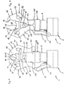
Bei dem in den Figuren 4 und 5 dargestellen Ausführungsbeispiel sind - wie auch bei den weiteren Ausführungsbeispielen - das vordere Gabelstück 7 und die vorn liegende Lagerplatte 9 weggelassen, so daß jetzt das hintere Gabelstück 30 und die dort anliegende Lagerplatte 31 zu sehen sind. Auf diese Weise ist die kinematische Verbindung zwischen den beweglichen Preßbacken 10, 11 sichtbar gemacht. Es handelt sich um eine Koppelstange 32, die am linken Ende mit dem Backenarm 14 und am rechten Ende mit dem Antriebshebel 23 jeweils benachbart der Lagerbolzen 12, 13 verbunden ist. Dies bewirkt bei Betätigung eines der beiden beweglichen Antriebshebel 22 bzw. 23 eine entgegengesetzte Schwenkbewegung bei der jeweils anderen Preßbacke 10, 11 mit der Folge, daß sich beide Preßbacken 10, 11 synchron und symmetrisch aus der Schließstellung (Figur 4) in die Offenstellung (Figur 5) bewegt wird.In the dargestellen in Figures 4 and 5 embodiment are - as well as in the other embodiments - the
Im Unterschied zu der Ausführungsform gemäß den Figuren 1 bis 3 geschieht hier die Bewegung der Preßbacken 10, 11 über einen Betätigungshebel 33, der an der dem Betätigungsschalter 29 abgewandten Seite des Gehäuses des Antriebs 2 über einen Lagerbolzen 34 verschwenkbar gelagert ist. Der Betätigungshebel 33 liegt damit im Griffbereich der Finger der Hand 26 und wird von diesen beim Halten des Preßgerätes 1 außenseitig umfaßt. Am oberen Ende liegt der Betätigungshebel 33 an der Außenseite des linken Antriebshebels 22 an.In contrast to the embodiment according to FIGS. 1 to 3, the movement of the
In Figur 4 befinden sich die beweglichen Preßbacken 10, 11 in der Schließstellung. Durch Verschwenken des Betätigungshebels 33 im Uhrzeigersinn durch entsprechendes Greifen der Finger der Hand 26 wird der linke Antriebshebel 22 nach innen, also entgegen dem Uhrzeigersinn und damit in Öffnungsrichtung bewegt. Die Bewegung wird über die Koppelstange 32 auf die rechte Preßbacke 11 übertragen, so daß beide Preßbacken 10, 11 sich öffnen und eine für die Ansetzung an einer Rohrverbindungsstelle ausreichend große Maulöffnung bilden.In Figure 4, the
Bei den Ausführungsbeispielen gemäß den Figuren 6 bis 8 ist wie bei dem Ausführungsbeispiel gemäß den Figuren 1 bis 3 kein zusätzlicher Betätigungshebel 33 vorhanden, d.h. die Betätigung der Preßbacken 10, 11 erfolgt hier - wie bei dem Preßgerät 1 gemäß den Figuren 1 bis 3 - über den Daumen 27 der Hand 26. Die Darstellungsweise entspricht der gemäß den Figuren 4 und 5, d.h. vorderes Gabelstück 7 und vordere Lagerplatte 9 sind weggelassen.In the exemplary embodiments according to FIGS. 6 to 8, as in the exemplary embodiment according to FIGS. 1 to 3, no
Die Ausführungsform gemäß den Figuren 6 und 7 weist eine Blockiereinrichtung 35 auf, die dazu bestimmt ist, die Preßbacken 10, 11 in der Offenstellung (Figur 7) gegen die Wirkung der in Schließrichtung beaufschlagenden Federvorspannung zu halten. Die Blockiereinrichtung 35 hat einen Blokkierring 36, der die Haltegabel 6 umgibt und auf ihr in Längsrichtung des Preßgerätes 1 verschieblich geführt ist. Der Blockierring 36 stützt sich über Druckfedern 37, 38 an der Haltegabel 6 ab, so daß er obenseitig unter Vorspannung an den Antriebshebeln 22, 23 anliegt.The embodiment according to FIGS. 6 and 7 has a blocking
In der Schließstellung (Figur 6) geschieht die Anlage im wesentlichen an der Unterseite der Antriebshebel 22, 23, so daß deren Beweglichkeit nicht durch den Blockierring 36 behindert wird. In der Offenstellung (Figur 7) der Antriebshebel 22, 23 schiebt sich der Blockierring 36 unter Einwirkung der Druckfedern 37, 38 nach oben und damit über die Außenseite der Antriebshebel 22, 23. Die Antriebshebel 22, 23 müssen deshalb nicht mehr - wie bei dem Ausführungsbeispiel gemäß den Figuren 1 bis 3 - von Hand in der Offenstellung gehalten werden, was je nach Vorspannung der Preßbacken 10, 11 kraftraubend sein kann. Nach Ansetzen des Preßgerätes 1 an einer Rohrverbindungsstelle wird der Blockierring 36 nach unten aus dem Bewegungsbereich der Antriebshebel 22, 23 geschoben, was auch hier durch eine entsprechende außenseitige Anlage und Bewegung des Daumens 27 der Hand 26 geschehen kann. Die Preßbacken 10, 11 sind dann frei und können sich aufgrund der Federvorspannung um die Rohrverbindungsstelle legen.In the closed position (Figure 6), the system is essentially on the underside of the
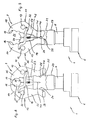
Bei dem Ausführungsbeispiel gemäß den Figuren 8 und 9 weist die Blockiereinrichtung 35 zwei Magnete 39, 40 auf, die in die Antriebsflächen 24, 25 gegenüberliegend eingelassen sind. In der Offenstellung der Preßbacken 10, 11 (Figur 9) kommen die Magnete 39, 40 zur gegenseitigen Anlage und halten die Preßbakken 10, 11 in dieser Stellung.In the embodiment according to FIGS. 8 and 9, the blocking
Die Preßbacke 19 wird von einer Öffnungsstange 41 durchsetzt, die mittels einer Druckfeder 42 in Richtung auf den Preßraum 21 vorgespannt und axial beweglich ist. In Offenstellung der Preßbacken 10, 11 ragt die Öffnungsstange 41 ein Stück über die Backenausnehmung 20 in den Preßraum 21 hinein. Am unteren Ende ist die Öffnungsstange 41 so ausgebildet, daß sie in den nach unten konisch zulaufenden Zwischenraum zwischen den beiden Antriebsflächen 24, 25 hineinragt und diesen ausfüllt.The
Beim Ansetzen des Preßgerätes in der Stellung gemäß Figur 9 an einer Rohrverbindungsstelle wird die Öffnungsstange 41 durch die Rohrverbindungsstelle in Richtung auf die Magnete 39, 40 bewegt und spreizt hierdurch die Antriebshebel 22, 23 ein Stück auseinander. Die Magnete 39, 40 werden gelöst, und die Preßbacken 10, 11 bewegen sich in die Schließstellung. Nach Abnahme des Preßgerätes 1 von der Rohrverbindungsstelle wird die Öffnungsstange 41 durch die Druckfeder 42 wieder in die in Figur 9 gezeigte Stellung gedrückt.When attaching the pressing device in the position shown in Figure 9 at a pipe joint, the opening
Die Figuren 10 und 11 zeigen das Preßwerkzeug 3 nach Abnahme des Antriebes 2, wobei auch hier die vorn liegende Lagerplatte 9 nicht dargestellt ist. Auf diese Weise wird der Blick freigegeben auf zwei Reibräder 43, 44, die frei drehbar in.der Preßbacke 19 nebeneinander gelagert sind und mit ihren Umfangsflächen aneinander anliegen. Die beweglichen Preßbacken 10, 11 weisen Übertragungsflächen 45, 46 auf, die als Kreisbogenabschnitte ausgebildet sind, welche konzentrisch zu den Lagerbolzen 12, 13 verlaufen. Sie liegen an den Umfangsflächen des jeweils benachbarten Reibrades 43, 44 an.Figures 10 and 11 show the
Wird beispielsweise der rechte Antriebshebel 23 aus der in Figur 10 gezeigten Schließstellung in die Offenstellung verschwenkt, also im Uhrzeigersinn, wird diese Schwenkbewegung über die Übertragungsfläche 46 auf das rechte Reibrad 44, von diesem auf das linke Reibrad 43 und von diesem auf die linke Übertragungsfläche 45 und damit auf die linke Preßbakke 10 übertragen. Die Pfeile in Figur 11 zeigen die jeweiligen Drehrichtungen an. Die Wirkung ist die gleiche wie bei der Koppelung der beiden Preßbacken 10, 11 über die Koppelstange 32.For example, if the
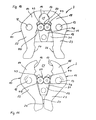
Das in den Figuren 12 und 13 dargestellte Preßwerkzeug 47 ist ebenfalls ohne Antrieb dargestellt. Es weist zwei spiegelbildlich ausgebildete Preßbacken 48, 49 auf, die zwischen zwei Lagerplatten 50 angeordnet sind, von denen die in der Ansicht vorn liegende Lagerplatte - wie bei den vorangegangenen Ausführungsbeispielen - weggelassen ist. An den Lagerplatten 50 sind die Preßbacken 48, 49 schwenkbar über Lagerbolzen 51, 52 gelagert. über einen weiteren Lagerbolzen 53 kann - ähnlich wie bei den Ausführungsbeispielen gemäß den Figuren 1 bis 9 - ein Antrieb angeschlossen werden.The
Die Preßbacken 48, 49 weisen oberhalb der Lagerbolzen 51, 52 Backenarme 54, 55 auf, in die gegenüberliegend Backenausnehmungen 56, 57 eingeformt sind. Im Gegensatz zu den bisher beschriebenen Ausführungsbeispielen fehlt eine dritte Preßbacke. Unterhalb der Lagerbolzen 51, 52 laufen die Preßbakken 48, 49 in Antriebshebel 58, 59 aus, die gegenüberliegend Antriebsflächen 60, 61 ausbilden. In den Zwischenraum zwischen die Antriebsflächen 60, 61 kann - wie bei den vorstehend beschriebenen Ausführungsbeispielen - der Antriebsstempel eines Antriebsmotors eingefahren werden.The
Die Preßbacken 48, 49 weisen etwas unterhalb der Ebene der Lagerbolzen 51, 52 gegenüberliegende, etwa halbkreisförmige Ausnehmungen 62, 63 auf, in die ein Übertragungsbolzen 64 kreisförmigen Querschnitts eingesetzt ist. In axialer Richtung wird der Übertragungsbolzen 64 von den beiden Lagerplatten 50 eingefaßt, so daß er nicht herausfallen kann. In geschlossenem Zustand (Figur 12) grenzen die Ausnehmungen 62, 63 obenseitig aneinander, während untenseitig ein Freiraum 65 besteht. Der Freiraum 65 ist so geformt, daß eine Verschwenkung der Preßbacken 48, 49 aus der Schließstellung (Figur 12) in die Offenstellung (Figur 13) möglich ist.The
Wird beispielsweise der rechte Antriebshebel 59 aus der in Figur 12 gezeigten Schließstellung in die Offenstellung verschwenkt, also im Uhrzeigersinn, wird diese Schenkbewegung durch die Innenfläche der zugehörigen Ausnehmung 63 auf den Übertragungsbolzen 64 und von diesem auf die Innenfläche der Ausnehmung 62 der linksseitigen Preßbacke 48 übertragen, so daß diese Preßbacke 48 im gleichen Sinn, d.h. ebenfalls in Öffnungsrichtung mitgenommen wird. Dabei ensteht ein Freiraum 66 im oberen Bereich der beiden Ausnehmungen 62, 63. Die nach rechts herausgezogenen Vergrößerungen zeigen die Veränderung der Stellung der Ausnehmungen 62, 63 und die Funktion des Übertragungsbolzen 64.For example, if the
Claims (14)
- Pressing tool (1) for connecting tubular workpieces (28), comprising at least two pressing jaws (10, 11, 19, 48, 49) surrounding a pressing space (21), which at least two pressing jaws are movable relatively towards one another in such a way that they can be moved to an open position for placement on the workpiece (28) and to a closed position for the pressing process by means of a drive motor (4), the at least two movable pressing jaws (10, 11, 48, 49) being so coupled that, upon actuation of one pressing jaw (10, 11, 48, 49), the other movable pressing jaw(s) (10, 11, 48, 49) is/are moved in the same direction, and the pressing tool (1) having on its housing a handle area for a holding hand (26), characterised in that the handle area is so provided that it permits holding and operation of the pressing tool (1) with one hand, which remains in the same position in the handle area, one of the movable pressing jaws (10, 11, 19, 48, 49) being movable by means of the holding hand (26) on the handle area in the direction of the open position and the pressing tool (1) including a switch (29) for switching on the drive (4), which switch (29) is so associated with the handle area that it can be operated with a finger (27) or thumb of the holding hand (26).
- Pressing tool according to claim 1, characterised in that the at least two movable pressing jaws (10, 11) are connected to one another via a coupling rod (32) in each case.
- Pressing tool according to claim 1 or 2, characterised in that the at least two movable pressing jaws (10, 11) are connected to one another via a friction coupling (43 to 46) or via a toothed coupling.
- Pressing tool according to any one of claims 1 to 3, characterised in that the at least two adjacent movable pressing jaws (48, 49) have two opposed recesses (62, 63) in which a coupling element (64) engages in such a way that upon actuation of one pressing jaw (48, 49) the other pressing jaw (49, 48) is moved in the same direction.
- Pressing tool according to any one of claims 1 to 4, characterised in that the coupled pressing jaws (10, 11, 48, 49) are spring-loaded in the closing direction.
- Pressing tool according to any one of claims 1 to 5, characterised in that the coupled pressing jaws (10, 11, 48, 49) include or are connected to drive levers (22, 23, 58, 59) which can be urged by a drive (2) in the closing direction and which end adjacently to the handle area.
- Pressing tool according to any one of claims 1 to 5, characterised in that the pressing tool (1) includes a handle area for holding the pressing tool (1) with one hand (26) and in that there is associated with the handle area an operating lever (33) via which one of the movable pressing jaws (10) can be urged in the direction of the open position.
- Pressing tool according to any one of claims 1 to 7, characterised in that a locking device (35) is provided for locking at least one of the coupled pressing jaws (10, 11) in the open position by positive or non-positive engagement.
- Pressing tool according to claim 8, characterised in that the locking device (35) is in the form of magnets (39, 40).
- Pressing tool according to claim 9, characterised in that the movable pressing jaws (10, 11) have drive levers (22, 23) which are provided with the magnets (39, 40) in such a way that they rest against one another in the open position of the pressing jaws (10, 11).
- Pressing tool according to claim 10, characterised in that the locking device (35) is configured as a movable locking element (36) which is movable to a locking position in the open position of the pressing jaws (10, 11).
- Pressing tool according to claim 11, characterised in that the locking element (36) is spring-loaded in the direction of the locking position.
- Pressing tool according to claim 12, characterised in that the pressing tool (1) has a handle area for holding the pressing tool (1) with one hand (26) and the locking element (36) is so associated with the handle area that the locking element (36) can be operated by this hand (26).
- Pressing tool according to any one of claims 8 to 13, characterised in that a movable feeler (41) projects into the pressing space (21), which feeler (41) is so coupled to the locking device (35, 39, 40) that it causes the locking device (35) to be released when the pressing tool (1) is placed on the workpiece (28).
Applications Claiming Priority (2)
| Application Number | Priority Date | Filing Date | Title |
|---|---|---|---|
| DE29703053U | 1997-02-21 | ||
| DE29703053U DE29703053U1 (en) | 1997-02-21 | 1997-02-21 | Pressing device |
Publications (3)
| Publication Number | Publication Date |
|---|---|
| EP0860245A2 EP0860245A2 (en) | 1998-08-26 |
| EP0860245A3 EP0860245A3 (en) | 2003-02-12 |
| EP0860245B1 true EP0860245B1 (en) | 2006-04-19 |
Family
ID=8036291
Family Applications (1)
| Application Number | Title | Priority Date | Filing Date |
|---|---|---|---|
| EP19980101788 Expired - Lifetime EP0860245B1 (en) | 1997-02-21 | 1998-02-03 | Pressing tool |
Country Status (2)
| Country | Link |
|---|---|
| EP (1) | EP0860245B1 (en) |
| DE (2) | DE29703053U1 (en) |
Cited By (4)
| Publication number | Priority date | Publication date | Assignee | Title |
|---|---|---|---|---|
| DE102007007294B3 (en) * | 2007-02-14 | 2008-07-10 | Rothenberger Ag | Drive unit with coupling for tool heads has housing with chamber for accumulators in end remote from coupling with total voltage of at least 12 Volts; chamber covered by removable cap has hydraulic pump with piston with transverse axis |
| DE102007061164A1 (en) * | 2007-12-17 | 2009-06-18 | Viega Gmbh & Co. Kg | Press tool with bistable tension mechanism |
| US10179398B2 (en) | 2011-05-09 | 2019-01-15 | Viega Technology Gmbh & Co. Kg | Jointing clamp and method for producing a compression joint |
| US11597064B2 (en) | 2018-08-23 | 2023-03-07 | Wezag Gmbh & Co. Kg | Pressing tongs or crimping pliers |
Families Citing this family (14)
| Publication number | Priority date | Publication date | Assignee | Title |
|---|---|---|---|---|
| DE10216213A1 (en) * | 2002-04-10 | 2003-10-23 | Klauke Gmbh Gustav | Electro-hydraulic pressing device and method for operating the same |
| DE19925504B4 (en) * | 1999-03-02 | 2011-08-18 | Gustav Klauke GmbH, 42855 | System for the safe application of pressfittings, pressing tools and pressfittings |
| ATE248045T1 (en) * | 2000-01-07 | 2003-09-15 | Arx Ag | PRESSING PLIERS |
| DE10101440B4 (en) | 2001-01-15 | 2017-10-26 | REMS-WERK Christian Föll und Söhne GmbH & Co. | Compression pliers |
| CA2458033C (en) | 2001-09-11 | 2010-06-08 | Emerson Electric Co. | Crimping assembly |
| US7059166B2 (en) | 2002-06-17 | 2006-06-13 | Emerson Electric Co. | Method and apparatus for assuring or determining appropriate closure of a crimp assembly |
| US7634859B2 (en) | 2003-03-06 | 2009-12-22 | Von Arx Ag | Press device |
| DE202006013693U1 (en) | 2006-09-07 | 2008-01-17 | Gustav Klauke Gmbh | Pressing jaw pair for hydraulic or electrical pressing devices |
| US7216523B2 (en) | 2004-07-02 | 2007-05-15 | Gustav Klauke Gmbh | Pair of pressing jaws for hydraulic or electric pressing tools, and insulating covering for a pressing jaw |
| US8074485B2 (en) * | 2008-07-08 | 2011-12-13 | Tyco Electronics Corporation | Tool head assemblies for pressing devices |
| US10226826B2 (en) | 2013-10-22 | 2019-03-12 | Milwaukee Electric Tool Corporation | Hydraulic power tool |
| DE102013112848B3 (en) | 2013-11-21 | 2015-04-23 | Viega Gmbh & Co. Kg | Press tool with bistable tension mechanism |
| DE102014112869B3 (en) | 2014-09-08 | 2016-01-07 | Viega Gmbh & Co. Kg | Press tool with switchable bistable clamping mechanism |
| US11641084B2 (en) | 2018-08-20 | 2023-05-02 | Hubbell Incorporated | Portable in-line dieless crimping tool |
Family Cites Families (8)
| Publication number | Priority date | Publication date | Assignee | Title |
|---|---|---|---|---|
| DE2136782C2 (en) * | 1971-07-23 | 1982-12-02 | Novopress GmbH Pressen und Presswerkzeuge & Co KG, 4000 Düsseldorf | Portable pressure fluid operated clamping tool |
| JPS53130600A (en) * | 1977-04-19 | 1978-11-14 | Naokazu Ueda | Pinchers with magnetic spring |
| FR2528750B1 (en) * | 1982-06-21 | 1987-01-16 | Bazantay Sarl Ets | CRIMPING TOOLS FOR PIPES, PIPES OR SIMILAR PRODUCTS |
| DE3423283A1 (en) * | 1984-06-23 | 1986-01-02 | Helmut Dipl.-Ing. 4040 Neuss Dischler | Clamping tool, in particular for connecting tubes and other sections |
| DE3713215A1 (en) * | 1987-04-18 | 1988-11-03 | Mag Maschinen Und Apparate Ges | Gripping device |
| DE3723330A1 (en) * | 1987-07-15 | 1989-01-26 | Paul Zahn | HYDRAULICALLY ACTUATED HAND DEVICE |
| DE4240427C1 (en) * | 1992-12-02 | 1994-01-20 | Novopress Gmbh | Press tool |
| DE29502032U1 (en) * | 1995-02-08 | 1995-03-23 | Rems-Werk Christian Föll und Söhne GmbH & Co, 71332 Waiblingen | Press tool |
-
1997
- 1997-02-21 DE DE29703053U patent/DE29703053U1/en not_active Expired - Lifetime
-
1998
- 1998-02-03 EP EP19980101788 patent/EP0860245B1/en not_active Expired - Lifetime
- 1998-02-03 DE DE59813489T patent/DE59813489D1/en not_active Expired - Lifetime
Cited By (6)
| Publication number | Priority date | Publication date | Assignee | Title |
|---|---|---|---|---|
| DE102007007294B3 (en) * | 2007-02-14 | 2008-07-10 | Rothenberger Ag | Drive unit with coupling for tool heads has housing with chamber for accumulators in end remote from coupling with total voltage of at least 12 Volts; chamber covered by removable cap has hydraulic pump with piston with transverse axis |
| EP1958732A2 (en) | 2007-02-14 | 2008-08-20 | Rothenberger AG | Drive device with a coupling for tool heads |
| DE102007061164A1 (en) * | 2007-12-17 | 2009-06-18 | Viega Gmbh & Co. Kg | Press tool with bistable tension mechanism |
| DE102007061164B4 (en) * | 2007-12-17 | 2010-03-04 | Viega Gmbh & Co. Kg | Press tool with bistable tension mechanism |
| US10179398B2 (en) | 2011-05-09 | 2019-01-15 | Viega Technology Gmbh & Co. Kg | Jointing clamp and method for producing a compression joint |
| US11597064B2 (en) | 2018-08-23 | 2023-03-07 | Wezag Gmbh & Co. Kg | Pressing tongs or crimping pliers |
Also Published As
| Publication number | Publication date |
|---|---|
| DE29703053U1 (en) | 1997-04-10 |
| EP0860245A3 (en) | 2003-02-12 |
| EP0860245A2 (en) | 1998-08-26 |
| DE59813489D1 (en) | 2006-05-24 |
Similar Documents
| Publication | Publication Date | Title |
|---|---|---|
| EP0860245B1 (en) | Pressing tool | |
| EP0451806B1 (en) | Press tool | |
| EP1223008B1 (en) | Crimping pliers | |
| DE4240427C1 (en) | Press tool | |
| EP3614507B1 (en) | Pressing or crimping tool | |
| DE3423283C2 (en) | ||
| DE2505915A1 (en) | DEVICE FOR EXPANSION OF PIPE ENDS | |
| DE112014003298T5 (en) | jig | |
| EP2734316B1 (en) | Handheld pressing tool | |
| DE19621877A1 (en) | Clamping and pressing tool for pipe fittings | |
| EP2233086A1 (en) | Tick removing device | |
| DE3617529C2 (en) | ||
| DE102009000153B3 (en) | Pliers for producing a sliding sleeve connection | |
| DE4323669C2 (en) | Device for extracting a chisel held in a chisel holder | |
| DE10243707B3 (en) | Hand tool for pressing pipe connections | |
| DE29717314U1 (en) | Press tool | |
| EP0631850A1 (en) | Device for processing workpieces | |
| DE10217266B4 (en) | Preßzange for pressing hollow bodies | |
| DE29517518U1 (en) | Press tool | |
| EP3718695B1 (en) | Press tool for a fitting with press tab | |
| WO1997030825A1 (en) | Tool for pressing pipe connections | |
| DE20305891U1 (en) | Pliers for release of pipe clips ha tubular control lines with internal steel wires operated by grip blocks and grips to release control parts and pipe | |
| DE1294300B (en) | Tool for axially pulling up or pulling back or pushing back rings etc. like | |
| DE29916524U1 (en) | Rivet setting tool | |
| DE20121845U1 (en) | Pipe wrench for the plumbing industry etc. has additional connection for manual drive |
Legal Events
| Date | Code | Title | Description |
|---|---|---|---|
| PUAI | Public reference made under article 153(3) epc to a published international application that has entered the european phase |
Free format text: ORIGINAL CODE: 0009012 |
|
| AK | Designated contracting states |
Kind code of ref document: A2 Designated state(s): AT BE CH DE DK ES FI FR GB GR IE IT LI LU MC NL PT SE |
|
| AX | Request for extension of the european patent |
Free format text: AL;LT;LV;MK;RO;SI |
|
| RIC1 | Information provided on ipc code assigned before grant |
Free format text: 7B 25B 27/14 A, 7H 01R 43/042 B, 7B 25B 27/10 B |
|
| PUAL | Search report despatched |
Free format text: ORIGINAL CODE: 0009013 |
|
| 17P | Request for examination filed |
Effective date: 20021205 |
|
| AK | Designated contracting states |
Designated state(s): AT BE CH DE DK ES FI FR GB GR IE IT LI LU MC NL PT SE |
|
| AX | Request for extension of the european patent |
Extension state: AL LT LV MK RO SI |
|
| AKX | Designation fees paid |
Designated state(s): CH DE FR GB IT LI |
|
| 17Q | First examination report despatched |
Effective date: 20031001 |
|
| GRAP | Despatch of communication of intention to grant a patent |
Free format text: ORIGINAL CODE: EPIDOSNIGR1 |
|
| GRAS | Grant fee paid |
Free format text: ORIGINAL CODE: EPIDOSNIGR3 |
|
| GRAA | (expected) grant |
Free format text: ORIGINAL CODE: 0009210 |
|
| AK | Designated contracting states |
Kind code of ref document: B1 Designated state(s): CH DE FR GB IT LI |
|
| PG25 | Lapsed in a contracting state [announced via postgrant information from national office to epo] |
Ref country code: IT Free format text: LAPSE BECAUSE OF FAILURE TO SUBMIT A TRANSLATION OF THE DESCRIPTION OR TO PAY THE FEE WITHIN THE PRESCRIBED TIME-LIMIT;WARNING: LAPSES OF ITALIAN PATENTS WITH EFFECTIVE DATE BEFORE 2007 MAY HAVE OCCURRED AT ANY TIME BEFORE 2007. THE CORRECT EFFECTIVE DATE MAY BE DIFFERENT FROM THE ONE RECORDED. Effective date: 20060419 Ref country code: GB Free format text: LAPSE BECAUSE OF FAILURE TO SUBMIT A TRANSLATION OF THE DESCRIPTION OR TO PAY THE FEE WITHIN THE PRESCRIBED TIME-LIMIT Effective date: 20060419 |
|
| REG | Reference to a national code |
Ref country code: GB Ref legal event code: FG4D Free format text: NOT ENGLISH |
|
| REF | Corresponds to: |
Ref document number: 59813489 Country of ref document: DE Date of ref document: 20060524 Kind code of ref document: P |
|
| GBV | Gb: ep patent (uk) treated as always having been void in accordance with gb section 77(7)/1977 [no translation filed] |
Effective date: 20060419 |
|
| PLAX | Notice of opposition and request to file observation + time limit sent |
Free format text: ORIGINAL CODE: EPIDOSNOBS2 |
|
| PLBI | Opposition filed |
Free format text: ORIGINAL CODE: 0009260 |
|
| 26 | Opposition filed |
Opponent name: RIDGID Effective date: 20070110 |
|
| EN | Fr: translation not filed | ||
| PLAF | Information modified related to communication of a notice of opposition and request to file observations + time limit |
Free format text: ORIGINAL CODE: EPIDOSCOBS2 |
|
| PLAF | Information modified related to communication of a notice of opposition and request to file observations + time limit |
Free format text: ORIGINAL CODE: EPIDOSCOBS2 |
|
| PLAF | Information modified related to communication of a notice of opposition and request to file observations + time limit |
Free format text: ORIGINAL CODE: EPIDOSCOBS2 |
|
| PLBP | Opposition withdrawn |
Free format text: ORIGINAL CODE: 0009264 |
|
| PLBD | Termination of opposition procedure: decision despatched |
Free format text: ORIGINAL CODE: EPIDOSNOPC1 |
|
| PG25 | Lapsed in a contracting state [announced via postgrant information from national office to epo] |
Ref country code: FR Free format text: LAPSE BECAUSE OF FAILURE TO SUBMIT A TRANSLATION OF THE DESCRIPTION OR TO PAY THE FEE WITHIN THE PRESCRIBED TIME-LIMIT Effective date: 20070309 |
|
| PLAB | Opposition data, opponent's data or that of the opponent's representative modified |
Free format text: ORIGINAL CODE: 0009299OPPO |
|
| PLBM | Termination of opposition procedure: date of legal effect published |
Free format text: ORIGINAL CODE: 0009276 |
|
| STAA | Information on the status of an ep patent application or granted ep patent |
Free format text: STATUS: OPPOSITION PROCEDURE CLOSED |
|
| 27C | Opposition proceedings terminated |
Effective date: 20080410 |
|
| PG25 | Lapsed in a contracting state [announced via postgrant information from national office to epo] |
Ref country code: FR Free format text: LAPSE BECAUSE OF FAILURE TO SUBMIT A TRANSLATION OF THE DESCRIPTION OR TO PAY THE FEE WITHIN THE PRESCRIBED TIME-LIMIT Effective date: 20060419 |
|
| REG | Reference to a national code |
Ref country code: CH Ref legal event code: NV Representative=s name: ALDO ROEMPLER PATENTANWALT |
|
| PGFP | Annual fee paid to national office [announced via postgrant information from national office to epo] |
Ref country code: CH Payment date: 20170221 Year of fee payment: 20 Ref country code: DE Payment date: 20170302 Year of fee payment: 20 |
|
| REG | Reference to a national code |
Ref country code: DE Ref legal event code: R071 Ref document number: 59813489 Country of ref document: DE |
|
| REG | Reference to a national code |
Ref country code: CH Ref legal event code: PL |