EP0860220A2 - Pressgerät - Google Patents
Pressgerät Download PDFInfo
- Publication number
- EP0860220A2 EP0860220A2 EP97114623A EP97114623A EP0860220A2 EP 0860220 A2 EP0860220 A2 EP 0860220A2 EP 97114623 A EP97114623 A EP 97114623A EP 97114623 A EP97114623 A EP 97114623A EP 0860220 A2 EP0860220 A2 EP 0860220A2
- Authority
- EP
- European Patent Office
- Prior art keywords
- press
- pressing
- curve
- limit value
- setpoint
- Prior art date
- Legal status (The legal status is an assumption and is not a legal conclusion. Google has not performed a legal analysis and makes no representation as to the accuracy of the status listed.)
- Granted
Links
Images

Classifications
-
- B—PERFORMING OPERATIONS; TRANSPORTING
- B25—HAND TOOLS; PORTABLE POWER-DRIVEN TOOLS; MANIPULATORS
- B25B—TOOLS OR BENCH DEVICES NOT OTHERWISE PROVIDED FOR, FOR FASTENING, CONNECTING, DISENGAGING OR HOLDING
- B25B27/00—Hand tools, specially adapted for fitting together or separating parts or objects whether or not involving some deformation, not otherwise provided for
- B25B27/02—Hand tools, specially adapted for fitting together or separating parts or objects whether or not involving some deformation, not otherwise provided for for connecting objects by press fit or detaching same
- B25B27/10—Hand tools, specially adapted for fitting together or separating parts or objects whether or not involving some deformation, not otherwise provided for for connecting objects by press fit or detaching same inserting fittings into hoses
-
- B—PERFORMING OPERATIONS; TRANSPORTING
- B21—MECHANICAL METAL-WORKING WITHOUT ESSENTIALLY REMOVING MATERIAL; PUNCHING METAL
- B21D—WORKING OR PROCESSING OF SHEET METAL OR METAL TUBES, RODS OR PROFILES WITHOUT ESSENTIALLY REMOVING MATERIAL; PUNCHING METAL
- B21D39/00—Application of procedures in order to connect objects or parts, e.g. coating with sheet metal otherwise than by plating; Tube expanders
- B21D39/04—Application of procedures in order to connect objects or parts, e.g. coating with sheet metal otherwise than by plating; Tube expanders of tubes with tubes; of tubes with rods
- B21D39/046—Connecting tubes to tube-like fittings
-
- B—PERFORMING OPERATIONS; TRANSPORTING
- B21—MECHANICAL METAL-WORKING WITHOUT ESSENTIALLY REMOVING MATERIAL; PUNCHING METAL
- B21D—WORKING OR PROCESSING OF SHEET METAL OR METAL TUBES, RODS OR PROFILES WITHOUT ESSENTIALLY REMOVING MATERIAL; PUNCHING METAL
- B21D39/00—Application of procedures in order to connect objects or parts, e.g. coating with sheet metal otherwise than by plating; Tube expanders
- B21D39/04—Application of procedures in order to connect objects or parts, e.g. coating with sheet metal otherwise than by plating; Tube expanders of tubes with tubes; of tubes with rods
- B21D39/048—Application of procedures in order to connect objects or parts, e.g. coating with sheet metal otherwise than by plating; Tube expanders of tubes with tubes; of tubes with rods using presses for radially crimping tubular elements
-
- B—PERFORMING OPERATIONS; TRANSPORTING
- B25—HAND TOOLS; PORTABLE POWER-DRIVEN TOOLS; MANIPULATORS
- B25B—TOOLS OR BENCH DEVICES NOT OTHERWISE PROVIDED FOR, FOR FASTENING, CONNECTING, DISENGAGING OR HOLDING
- B25B27/00—Hand tools, specially adapted for fitting together or separating parts or objects whether or not involving some deformation, not otherwise provided for
- B25B27/14—Hand tools, specially adapted for fitting together or separating parts or objects whether or not involving some deformation, not otherwise provided for for assembling objects other than by press fit or detaching same
- B25B27/146—Clip clamping hand tools
-
- Y—GENERAL TAGGING OF NEW TECHNOLOGICAL DEVELOPMENTS; GENERAL TAGGING OF CROSS-SECTIONAL TECHNOLOGIES SPANNING OVER SEVERAL SECTIONS OF THE IPC; TECHNICAL SUBJECTS COVERED BY FORMER USPC CROSS-REFERENCE ART COLLECTIONS [XRACs] AND DIGESTS
- Y10—TECHNICAL SUBJECTS COVERED BY FORMER USPC
- Y10T—TECHNICAL SUBJECTS COVERED BY FORMER US CLASSIFICATION
- Y10T29/00—Metal working
- Y10T29/49—Method of mechanical manufacture
- Y10T29/49826—Assembling or joining
- Y10T29/49908—Joining by deforming
- Y10T29/49909—Securing cup or tube between axially extending concentric annuli
- Y10T29/49913—Securing cup or tube between axially extending concentric annuli by constricting outer annulus
-
- Y—GENERAL TAGGING OF NEW TECHNOLOGICAL DEVELOPMENTS; GENERAL TAGGING OF CROSS-SECTIONAL TECHNOLOGIES SPANNING OVER SEVERAL SECTIONS OF THE IPC; TECHNICAL SUBJECTS COVERED BY FORMER USPC CROSS-REFERENCE ART COLLECTIONS [XRACs] AND DIGESTS
- Y10—TECHNICAL SUBJECTS COVERED BY FORMER USPC
- Y10T—TECHNICAL SUBJECTS COVERED BY FORMER US CLASSIFICATION
- Y10T29/00—Metal working
- Y10T29/53—Means to assemble or disassemble
- Y10T29/53004—Means to assemble or disassemble with means to regulate operation by use of templet, tape, card or other replaceable information supply
- Y10T29/53009—Means to assemble or disassemble with means to regulate operation by use of templet, tape, card or other replaceable information supply with comparator
-
- Y—GENERAL TAGGING OF NEW TECHNOLOGICAL DEVELOPMENTS; GENERAL TAGGING OF CROSS-SECTIONAL TECHNOLOGIES SPANNING OVER SEVERAL SECTIONS OF THE IPC; TECHNICAL SUBJECTS COVERED BY FORMER USPC CROSS-REFERENCE ART COLLECTIONS [XRACs] AND DIGESTS
- Y10—TECHNICAL SUBJECTS COVERED BY FORMER USPC
- Y10T—TECHNICAL SUBJECTS COVERED BY FORMER US CLASSIFICATION
- Y10T29/00—Metal working
- Y10T29/53—Means to assemble or disassemble
- Y10T29/53039—Means to assemble or disassemble with control means energized in response to activator stimulated by condition sensor
- Y10T29/53061—Responsive to work or work-related machine element
-
- Y—GENERAL TAGGING OF NEW TECHNOLOGICAL DEVELOPMENTS; GENERAL TAGGING OF CROSS-SECTIONAL TECHNOLOGIES SPANNING OVER SEVERAL SECTIONS OF THE IPC; TECHNICAL SUBJECTS COVERED BY FORMER USPC CROSS-REFERENCE ART COLLECTIONS [XRACs] AND DIGESTS
- Y10—TECHNICAL SUBJECTS COVERED BY FORMER USPC
- Y10T—TECHNICAL SUBJECTS COVERED BY FORMER US CLASSIFICATION
- Y10T29/00—Metal working
- Y10T29/53—Means to assemble or disassemble
- Y10T29/53087—Means to assemble or disassemble with signal, scale, illuminator, or optical viewer
Definitions
- the invention relates to a pressing device for connecting workpieces, with a press tool and a motor drive for actuating the pressing tool via a pressing path and with a control device, the drive control device to influence the drive.
- the pressing is done with the help of pressing devices like the one below in various embodiments, for example in the DE-C-21 3782, DE-A-34 23 283, EP-A-0 451 806, EP-B-0 361 630 and DE-U-296 04 276.5 are known.
- the presses have one Press tool with at least two or even more Press jaws that are used radially inward during the pressing process Formation of a substantially closed press room moves will.
- the pressing tool is interchangeable on the rest Part of the pressing device attached so that one to each Suitable press tool diameter used for the press fitting can be.
- the Drive for the movement of the press jaws provided that additionally with a hydraulic unit can be combined.
- the Drive back a pressing path that usually started with one Free travel begins until the press jaws on the press fitting come to the plant.
- the deformation follows on the further pressing path of the press fitting and the pipe end up to a final press position.
- the drive is switched off automatically it in the form of a force limiting element, for example a torque clutch or a hydraulic switching valve, be it by a limit switch in connection with a Jaw closing sensor on the pressing tool (DE-U-296 02 240.3).
- a special problem is the interruption of a pressing process for example due to a power failure Repressing is a long free path to overcome, which takes time costs and depending on the control of the drive to build high kinetic energies with the risk of sudden impact the press jaws on the only partially pressed press fitting to lead.
- the invention has for its object a pressing device type mentioned at the outset so that incorrect pressing avoided with higher reliability or at least recognized can be.
- the basic idea of the invention is therefore in a pressing device the generic type a fault detection device to be provided in the event of a deviation with the compression resistance correlating physical size of one Normal course for a signal formation and / or a shutdown of the drive leads.
- the signal formation can be optical or acoustically, in the simplest form as Alarm signaling or flashing of an alarm lamp or alarm buzzer, but also differentiated depending on the type of disorder Signaling up to a display with a readable fault message or in the form of a speech.
- the operator receives more or less specified information that there is a fault and therefore the pressing process be interrupted for the purpose of further review should. Instead, or in combination with signaling the drive can also be switched off automatically, so that the pressing process at least not easily can continue.
- the inventive Fault detection device an essential higher security against mispressing is gained what with a view to the great damage potential of such mispressing is extremely important.
- the speed it can also be used as a physical quantity the force to be applied, for example by means of strain gauges, be recorded or - analogously - the torque to be applied.
- the average electrical current is suitable as an indicator of the resistance to compression, because that too changes with this.
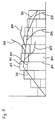
- At least one further upper and / or lower limit value curve is or are recorded on the inadmissible side of the first limit value curve or lie.
- a narrower and a wider limit corridor formed that can be used to Signaling device and the shutdown device depending to control which limit corridor to the impermissible Side is left.
- the wider limit corridor should be designed so that it Do not compress press fittings that are too small or too large is left, but only, for example, in the event of a break or a blockage, i.e. a comparatively heavy one Disorder.
- the setpoint curve can have two stages be in such a way that in the first phase of the press path and here a small one, especially when overcoming the free travel Performance is specified, which is then applied to the Press fittings in adaptation to the resulting compression resistance is increased.
- the setpoint curve can be very close adapted to the course of the compression resistance in the manner be that the stress on the power Parts of the pressing device, for example when the Press jaws on the press fitting and especially at the end of the Press way, and thus the creeping changes as a result Wear can be kept low.
- the Fault detection device can each by location and type of change in the physical detected The size of the faults is recorded relatively precisely and also differentiated can be specified.
- the power control device and the setpoint curve or the setpoint curves can be part of a sequence control be designed without feedback.
- the power control device gets according to a desired course the physical quantity associated with the compression resistance correlated, a performance target - for example by adjusting the leading edge in a triac as Power control or pulse width modulation at one Transistor - which at normal compression to a adapted course leads.
- a sequential control a sequential control with Feedback is provided in which the setpoint curve or each setpoint course from a defining the control bandwidth Control corridor with upper and lower control limits is included.
- Both with the sequential control and with the sequential regulation come along as a variable correlating to the compression resistance the speed of the drive also the force to be applied - with a hydraulic drive also the hydraulic pressure - and that torque to be applied and also the average electrical Electricity in question. It is particularly advantageous if the controlled variable with the physical quantity that with the compression resistance correlated, is identical. In that case, the Limit value curves for the physical quantity very closely to the Setpoint curve can be adjusted, because the control ensures that the control corridor does not normally leave becomes. In this way, a fault that can no longer be corrected detected relatively quickly, especially if the control limits with the limit value curves for the physical Size identical, so the standard corridor and that of the Threshold values included corridor congruent are.
- the pressing tools are usually interchangeably attached to the drive member to the drive part for the pressing of press fittings and pipes to be able to use different diameters.
- the only setpoint curve is not for all pressing tools optimal.
- the limit value curves there should be several limit value curves and if necessary, setpoint curves defined, in particular stored be, expediently so that for each type of press tool adapted limit value profiles and, if necessary, set value profiles are set.
- the pressing device Material sensor for example in the form of an eddy current sensor, to record the material of the workpieces.
- the use of the pressing device is not only on the pressing of workpieces of a certain material limited, but can also be used for other materials are softer or harder and therefore have a different compression resistance have, are needed.
- the Drive control device a self-adaptation device over which the limit value curves and, if applicable also the setpoint curve for the actual compression resistance is or are adaptable.
- Such self-adaptation facilities are known per se in control technology. they allow es, the limit value curves and, if applicable, the associated setpoint curve in principle in parallel in adaptation to shift to the actual compression resistance, by performing a test injection. With this test pressing the self-adaptation device provides the deviation of the stored limit value curves and puts the deviating values in the place of the previously saved ones Values.
- the self-adaptation device of Can be activated by hand, so that self-adaptation only then is possible if a test injection is carried out. On in this way it is avoided that incorrect limit value curves or setpoint curves can be saved.
- the self-adaptation facility can be especially related to the adjustment to other materials or wall thicknesses of press fittings and pipe end as well as for calibration on a new one Press device can be used advantageously.
- At least one setpoint curve for the full press travel and for at least one more of these or each of these setpoint curves
- Setpoint curve for a partial press path after an interruption of the pressing process are recorded.
- a plurality of such setpoint curves are stored can be, depending on the the interruption of the pressing process.
- Limit value curves are adapted to this setpoint curve assigned so that even after an interruption Pressing a fault detection adapted to the new setpoint curve he follows.
- a switch arrangement that can be operated by hand can be used for setting the respective limit value curves and, if necessary, setpoint curves can be provided. In this However, operating errors cannot be ruled out. From It is therefore advantageous if it is derived from DE-U-297 03 052.3 basic idea of the present invention in the sense is used that the press tool a coding over which the associated limit value curves and possibly the associated setpoint curve can be selected. This poses sure that after changing the press tool suitable limit value curves and - if a controller or Regulation of the drive is provided, including the setpoint curve to be chosen.
- the coding can be used as a electrical or electronic component be formed, that with the drive device via a transmission link connected is.
- Examples can be found in DE-GM 297 03 052.3.
- a memory chip comes in as coding Question because in it a variety of different encodings can be saved.
- the limit value curve or the limit value curves as well if necessary, a suitable setpoint curve in this memory chip to hold on.
- the memory chip can then connect of the pressing tool with the drive part of the pressing device as Part of the drive control can be designed.
- Such a memory chip can also be used to characteristic press path for the pressing tool in question - or similarly to save the pressing time. When reached the end of the press path or end of the press time can then be an optical one or emitted an acoustic signal and / or the drive was switched off will.
- the pressing tool has a position sensor and that in the memory chip a partial press path or a partial press time is stored, wherein the drive is controlled so that only the Partial press travel is carried out when the position sensor is activated becomes.
- the press path or the partial press path can for one certain size of the press tool can be set. More appropriate it is, however, the press path or partial press path at each Press tool to determine experimentally and the relevant Store value in the memory chip. That way secured that the pressing tool up to its final pressing position, however, it does not go beyond, namely regardless of the manufacturing tolerances Deviations.
- a locking device to block the drive Control of the shutdown device is provided, the Locking device only after activating a special unlocking device can be overcome.
- This training is intended to prevent that an interrupted pressing process only druch actuating the on / off switch again becomes.
- the unlocking device can also be used for the post-injection provided limit value courses and if necessary select the appropriate setpoint curve, and also additionally in adaptation to the until the interruption of the pressing process Press path covered. To capture the latter too should be a starting sensor to record the starting position of the pressing tool and a distance and / or time sensor be provided. As a displacement transducer is in particular a revolution counter is suitable.
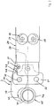
- the pressing device 1 shown in Figures 1 to 3 is in two parts constructed and consists essentially of a drive part 2 and a pressing tool 3. Both are over one Coupling bolts 4 connected to one another in an articulated manner.
- An electric drive motor is located in the drive part 2 5 with a drive shaft 6, which is in a bearing 7 is stored.
- a drive pinion 8 is arranged at the free end, that meshes with a gear 9, which is on an intermediate shaft 10 sits.
- the intermediate shaft 10 is in the bearings 11 and 12 rotatably mounted. It carries a pinion 13, which meshes with a gear 14, the part of a spindle nut 15 is.
- the spindle nut 15 is axially immovable in the bearings 16, 17 stored.
- the spindle nut 15 is one Spindle 18 passes through, the drive motor 5 removed lying end is provided with a clevis 19.
- Spindle nut 15 and spindle 18 mesh in such a way that at Rotation of the spindle nut 15 an axial displacement of the Spindle 18 is effected.
- the spindle 18 becomes non-rotatable guided.
- This residual press path is obtained by the following calibration process.
- the jaw closing sensor 54 is set so that it already responds, i.e. the circuit 51 interrupts when the Jaw arms 38, 39 not quite their final pressing position shown in Figure 3 achieved.
- the press tool 3 is then on an appropriate calibration device or with the help of the drive part 2 of the pressing device 1 several times with a specific Force over the full press path to a final press position, in which the drive arms 36, 37 abut one another on the end face, moved together.
- the press jaw lever 34, 35 after the jaw closing sensor 54 has responded still put back. This is repeated until the Do not differentiate or only minimally differentiate the measured remaining press paths, the pressing tool 3 has therefore settled.
- the one after that determined residual press path is stored in the memory chip 100 accepted. It is characteristic of the pressing tool in question 3. Due to manufacturing tolerances Pressing tools 3 of the same size, different residual press paths surrender.
- the calibration described above ensures that the Drive motor 5 in a defined, for that Pressing tool 3 characteristic final pressing position switched off becomes.
- the jaw closing sensor 54 is released during the pressing process the distance measurement for the stored remaining press path, whereby this by counting the pulses detected by the speed sensor 25 happens. After driving the remaining press path, the drive motor 5 switched off via the switch-off element 66.
- an automatic selection of the appropriate one can be made Restpreßweg done in such a way that during the Pressing the compression resistance at a certain Point of the pressing path and its value as a selection criterion is used.
- This can be the case with the present pressing device 1 happen in such a way that each one is characteristic Deviation from curve 79 is determined at the specific location and the measure of the deviation as a selection criterion is used.
- an additional actual value sensor for a physical to provide a size that corresponds to the compression resistance, for example in the form of a strain gauge on one loaded part of the press tool 3 or a torque tap on the drive shaft 6.
Landscapes
- Engineering & Computer Science (AREA)
- Mechanical Engineering (AREA)
- Control Of Presses (AREA)
- Automatic Assembly (AREA)
- Press Drives And Press Lines (AREA)
- Mounting, Exchange, And Manufacturing Of Dies (AREA)
Abstract
Description
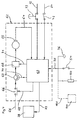
- die Antriebssteuereinrichtung hat eine Störungserfassungseinrichtung;
- die Störungserfassungseinrichtung weist einen Istwertaufnehmer auf;
- der Istwertaufnehmer ist für die Erfassung einer physikalischen Größe als Istwert geeignet, welche mit dem Verpressungswiderstand korreliert;
- in der Störungserfassungseinrichtung ist wenigstens ein Grenzwertverlauf festgehalten;
- die Störungserfassungseinrichtung weist eine Störungsvergleichseinrichtung auf, die bei einer Verpressung eine Überprüfung darauf hin vornimmt, ob der jeweilige Istwert auf der zulässigen oder nicht zulässigen Seite des zugehörigen Grenzwertverlaufs liegt;
- zu der Störungserfassungseinrichtung gehört eine Signaleinrichtung und/oder eine Abschalteinrichtung für den Antrieb, welcher angesteuert wird bzw. werden, wenn der Istwert auf der unzulässigen Seite des Grenzwerts liegt.
- Figur 1
- den Antriebsteil eines Preßgeräts im Längsschnitt;
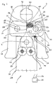
- Figur 2
- den oberen Teil des Antriebsteils gemäß Figur 1 mit einem teilweise dargestellten Preßwerkzeug;
- Figur 3
- das Preßwerkzeug gemäß Figur 2 in vergrößerter Darstellung;
- Figur 4
- eine vereinfachte Darstellung der Steuerung des Preßgeräts gemäß den Figuren 1 bis 3 und
- Figur 5
- eine Grafik zur Veranschaulichung der Drehzahlregelung für die Steuerung gemäß Figur 4.
Claims (33)
- Preßgerät (1) zum Verbinden von Werkstücken (44, 45), mit einem Preßwerkzeug (3) und einem motorischen Antrieb zur Betätigung des Preßwerkzeugs (3) über einen Preßweg sowie mit einer Steuereinrichtung (26), die eine Antriebssteuereinrichtung (62) zur Beeinflussung des Antriebs (5) aufweist, gekennzeichnet durch folgende Merkmale:die Antriebssteuereinrichtung (62) hat eine Störungserfassungseinrichtung;die Störungserfassungseinrichtung weist einen Istwertwertaufnehmer (23, 24, 25) auf;der Istwertaufnehmer (23, 24, 25) ist für die Erfassung einer physikalischen Größe als Istwert geeignet, welche mit dem Verpressungswiderstand korreliert;in der Störungserfassungseinrichtung ist wenigstens ein Grenzwertverlauf (83, 84) für den Istwert festgehalten;die Störungserfassungseinrichtung weist eine Vergleichseinrichtung auf, die bei einem Verpressen eine Überprüfung darauf hin vornimmt, ob der jeweilige Istwert auf der zulässigen oder nicht zulässigen Seite des zugehörigen Grenzwertsverlaufs (83, 84) liegt;zu der Störungserfassungseinrichtung gehört eine Signaleinrichtung (78) und/oder eine Abschalteinrichtung (66) für den Antrieb (5), welche angesteuert wird bzw. werden, wenn der Istwert auf der unzulässigen Seite des zugehörigen Grenzwerts liegt.
- Preßgerät nach Anspruch 1,
dadurch gekennzeichnet, daß wenigstens ein oberer und wenigstens ein unterer Grenzwertverlauf (83, 84) festgehalten sind. - Preßgerät nach Anspruch 2,
dadurch gekennzeichnet, daß zumindest ein Grenzwertverlauf (83, 84) an den Verlauf des Istwerts bei störungsfreier Verpressung unter Bildung eines Grenzwertkorridors angepaßt ist. - Preßgerät nach Anspruch 3,
dadurch gekennzeichnet, daß wenigstens ein weiterer oberer und/oder unterer Grenzwertverlauf (83, 84) festgehalten ist bzw. sind, der bzw. die jeweils auf der unzulässigen Seite des ersten Grenzwertverlaufs liegt bzw. liegen. - Preßgerät nach Anspruch 4,
dadurch gekennzeichnet, daß dann, wenn der Istwert auf der unzulässigen Seite des ersten Grenzwertverlaufs, (83, 84) aber noch auf der zulässigen Seite des benachbarten weiteren Grenzwertverlaufs liegt, die Signaleinrichtung (78) angesteuert wird, und daß dann, wenn der Istwert auf der unzulässigen Seite auch des weiteren Grenzwertverlaufs liegt, die Abschalteinrichtung (66) angesteuert wird. - Preßgerät nach einem der Ansprüche 1 bis 5,
dadurch gekennzeichnet, daß der Grenzwertverlauf bzw. wenigstens ein Grenzwertverlauf (83, 84) über den Preßweg in Bereiche (80) aufgeteilt sind, wobei jedem Bereich (80) eine spezifische Signalgabe zugeordnet ist bzw. sind. - Preßgerät nach einem der Ansprüche 1 bis 6,
dadurch gekennzeichnet, daß die Antriebssteuereinrichtung (62) eine Leistungssteuereinrichtung (67) als Stellglied aufweist und daß wenigstens ein Sollwertverlauf (79) als Führungsgröße festgehalten ist, über den eine dem Sollwertverlauf entsprechende Stellgröße für die Beeinflussung der Leistungssteuereinrichtung (67) erzeugt wird. - Preßgerät nach einem der Ansprüche 1 bis 7,
dadurch gekennzeichnet, daß die Leistungssteuereinrichtung (67) sowie der Sollwertverlauf bzw. die Sollwertverläufe Teile einer Folgesteuerung sind. - Preßgerät nach Anspruch 8,
dadurch gekennzeichnet, daß die physikalische Größe, welche mit dem Verpressungswiderstand korreliert, die Drehzahl des Antriebs (5), die aufzubringende Kraft, das aufzubringende Drehmoment und/oder der dem Antrieb (5) zugeführte elektrische Strom ist bzw. sind. - Preßgerät nach Anspruch 7,
dadurch gekennzeichnet, daß die Leistungssteuereinrichtung (67) und der Sollwertverlauf (79) bzw. die Sollwertverläufe Teil einer Folgeregelung sind. - Preßgerät nach Anspruch 10,
dadurch gekennzeichnet, daß die Regelgröße der Folgeregelung die Drehzahl des Antriebs (5) ist. - Preßgerät nach Anspruch 10 oder 11,
dadurch gekennzeichnet, daß die Regelgröße der Folgeregelung mit der physikalischen Größe, die mit dem Verpressungswiderstand korreliert, identisch ist. - Preßgerät nach einem der Ansprüche 10 bis 12,
dadurch gekennzeichnet, daß der Sollwertverlauf (79) bzw. jeder Sollwertverlauf von einem die Regelbandbreite definierenden Regelkorridor (82) mit oberen und unteren Regelgrenzen (83, 84) eingeschlossen ist. - Preßgerät nach Anspruch 13,
dadurch gekennzeichnet, daß die Regelgrenzen (83, 84) mit den Grenzwertverläufen (83, 84) identisch sind. - Preßgerät nach einem der Ansprüche 1 bis 14,
dadurch gekennzeichnet, daß mehrere Grenzwertverläufe (83, 84) sowie ggf. mehrere Sollwertverläufe (79) festgelegt sind. - Preßgerät nach Anspruch 15,
dadurch gekennzeichnet, daß die Grenzwertverläufe (83, 84) sowie ggf. die Sollwertverläufe (79) an verschieden große Preßwerkzeuge angepaßt sind. - Preßgerät nach Anspruch 15 oder 16,
dadurch gekennzeichnet, daß das Preßgerät (1) einen Werkstoffsensor zur Erfassung des Werkstoffs der Werkstücke (44, 45) aufweist, wobei über den Werkstoffsensor die Auswahl der Grenzwertverläufe (83, 84) und ggf. des Sollwertverlaufs (79) erfolgt. - Preßgerät nach Anspruch 16,
dadurch gekennzeichnet, daß die Grenzwertverläufe (83, 84) sowie ggf. die Sollwertverläufe (79) für verschiedene Eigenschaften der Werkstücke festgelegt sind. - Preßgerät nach einem der Ansprüche 16 bis 18,
dadurch gekennzeichnet, daß eine von Hand bedienbare Schalteranordnung (76) für die Einstellung der jeweiligen Grenzwertverläufe (83, 84) und ggf. des Sollwertverlaufs (79) vorgesehen sind. - Preßgerät nach einem der Ansprüche 1 bis 19,
dadurch gekennzeichnet, daß die Anstriebssteuereinrichtung (62) eine Selbstadaptionseinrichtung aufweist, über die die Grenzwertverläufe (83, 84) und gegebenenfalls der Sollwertverlauf (79) an den tatsächlichen Verpressungswiderstand anpaßbar ist bzw. sind. - Preßgerät nach einem der Ansprüche 1 bis 20,
dadurch gekennzeichnet, daß dem Sollwertverlauf (79) bzw. jedem Sollwertverlauf entsprechend angepaßte weitere Sollwertverläufe (90) sowie Grenzwertverläufe für eine Teilverpressung zugeordnet sind. - Preßgerät nach Anspruch 210,
dadurch gekennzeichnet, daß die Zuordnung des Sollwertverlaufs (90) bzw. der Sollwertverläufe für die Teilverpressung zu dem Sollwertverlauf (79) bzw. den Sollwertverläufen für die Vollverpressung automatisch mit deren Wahl erfolgt. - Preßgerät nach einem der Ansprüche 1 bis 22,
dadurch gekennzeichnet, daß das Preßwerkzeug (3) eine Codierung (50, 100) aufweist, über die die zugehörigen Grenzwertverläufe (83, 84) sowie ggf. der zugehörige Sollwertverlauf (79) bestimmt werden. - Preßgerät nach Anspruch 23,
dadurch gekennzeichnet, daß die Codierung als ein elektrisches oder elektronisches Bauteil (50, 100) ausgebildet ist, das mit der Antriebssteuereinrichtung (62) über ein Übertragungsglied verbunden ist. - Preßgerät nach Anspruch 23,
dadurch gekennzeichnet, daß die Codierung als Speicherchip (100) mit wenigstens einem darin gespeicherten Grenzwertverlauf (83, 84) ausgebildet ist. - Preßgerät nach Anspruch 25,
dadurch gekennzeichnet, daß in dem Speicherchip (100) auch der zugehörige Sollwertverlauf (79) gespeichert ist. - Preßgerät nach Anspruch 25 oder 26,
dadurch gekennzeichnet, daß eine Einrichtung zum Laden der in dem Speicherchip (100) gespeicherten Grenzwertverläufe (83, 84) und ggf. Sollwertverläufe (79) in die Antriebssteuereinrichtung (62) vorgesehen ist. - Preßgerät nach einem der Ansprüche 25 bis 27,
dadurch gekennzeichnet, daß in dem Speicherchip (199) der Preßweg oder eine Preßzeit gespeichert ist und daß bei Erreichen des Preßwegendes bzw. Preßzeitendes ein optisches oder akustisches Signal abgegeben und/oder der Antrieb (5) abgeschaltet wird. - Preßgerät nach einem der Ansprüche 25 bis 28,
dadurch gekennzeichnet, daß das Preßwerkzeug (1) einen Stellungsaufnehmer (54) aufweist und daß in dem Speicherchip (100) ein Restpreßweg bzw. eine Restpreßzeit gespeichert ist, wobei der Antrieb (5) derart gesteuert wird, daß nur noch über den Restpreßweg bzw. die Restpreßzeit verfahren wird, wenn der Stellungsaufnehmer (54) aktiviert wird. - Preßgerät nach einem der Ansprüche 1 bis 29,
dadurch gekennzeichnet, daß eine Sperreinrichtung zur Blockierung des Antriebs (5) bei Ansteuerung der Abschalteinrichtung (66) vorgesehen ist, wobei die Sperreinrichtung erst nach Betätigung einer besonderen Entsperreinrichtung überwindbar ist. - Preßgerät nach einem der Ansprüche 1 bis 30,
dadurch gekennzeichnet, daß ein Startaufnehmer (47, 48, 49) zur Erfassung der Anfangsstellung des Preßwerkzeugs (3) vorgesehen ist. - Preßgerät nach einem der Ansprüche 1 bis 31,
dadurch gekennzeichnet, daß die Steuereinrichtung einen Weg- und/oder Zeitaufnehmer (23, 24, 25) für den Preßvorgang aufweist. - Preßgerät nach Anspruch 32,
dadurch gekennzeichnet, daß der Wegaufnehmer als Umdrehungszähler (23, 24, 25) ausgebildet ist.
Priority Applications (1)
| Application Number | Priority Date | Filing Date | Title |
|---|---|---|---|
| US09/026,771 US6240626B1 (en) | 1997-02-21 | 1998-02-20 | Pressing device |
Applications Claiming Priority (2)
| Application Number | Priority Date | Filing Date | Title |
|---|---|---|---|
| DE29703052U | 1997-02-21 | ||
| DE29703052U DE29703052U1 (de) | 1997-02-21 | 1997-02-21 | Preßgerät zum Verbinden von Werkstücken |
Publications (3)
| Publication Number | Publication Date |
|---|---|
| EP0860220A2 true EP0860220A2 (de) | 1998-08-26 |
| EP0860220A3 EP0860220A3 (de) | 2000-07-26 |
| EP0860220B1 EP0860220B1 (de) | 2003-02-05 |
Family
ID=8036290
Family Applications (4)
| Application Number | Title | Priority Date | Filing Date |
|---|---|---|---|
| EP97114624A Expired - Lifetime EP0860221B1 (de) | 1997-02-21 | 1997-08-23 | Pressgerät |
| EP97114625A Expired - Lifetime EP0860222B1 (de) | 1997-02-21 | 1997-08-23 | Pressgerät sowie Verfahren zum Einspeichern des Presswegs oder des Restpresswegs |
| EP97114623A Expired - Lifetime EP0860220B1 (de) | 1997-02-21 | 1997-08-23 | Pressgerät |
| EP98102326A Expired - Lifetime EP0860223B1 (de) | 1997-02-21 | 1998-02-11 | Pressgerät zum Verbinden von Werkstücken |
Family Applications Before (2)
| Application Number | Title | Priority Date | Filing Date |
|---|---|---|---|
| EP97114624A Expired - Lifetime EP0860221B1 (de) | 1997-02-21 | 1997-08-23 | Pressgerät |
| EP97114625A Expired - Lifetime EP0860222B1 (de) | 1997-02-21 | 1997-08-23 | Pressgerät sowie Verfahren zum Einspeichern des Presswegs oder des Restpresswegs |
Family Applications After (1)
| Application Number | Title | Priority Date | Filing Date |
|---|---|---|---|
| EP98102326A Expired - Lifetime EP0860223B1 (de) | 1997-02-21 | 1998-02-11 | Pressgerät zum Verbinden von Werkstücken |
Country Status (3)
| Country | Link |
|---|---|
| US (1) | US6202290B1 (de) |
| EP (4) | EP0860221B1 (de) |
| DE (5) | DE29703052U1 (de) |
Cited By (10)
| Publication number | Priority date | Publication date | Assignee | Title |
|---|---|---|---|---|
| EP1092487A2 (de) * | 1999-10-15 | 2001-04-18 | Gustav Klauke GmbH | Verpressgerät mit Pressbacken |
| EP1125682A2 (de) * | 2000-02-16 | 2001-08-22 | Murata Kikai Kabushiki Kaisha | Stanzmaschine |
| US7059166B2 (en) | 2002-06-17 | 2006-06-13 | Emerson Electric Co. | Method and apparatus for assuring or determining appropriate closure of a crimp assembly |
| US7155955B2 (en) | 2001-09-11 | 2007-01-02 | Emerson Electric Co. | Crimping assembly |
| DE202009003196U1 (de) | 2009-03-10 | 2010-04-29 | Novopress Gmbh Pressen Und Presswerkzeuge & Co. Kommanditgesellschaft | Handführbare Antriebseinrichtung für ein Pressgerät |
| DE202009003197U1 (de) | 2009-03-10 | 2010-05-06 | Novopress Gmbh Pressen Und Presswerkzeuge & Co. Kommanditgesellschaft | Handführbare Antriebseinrichtung für ein Pressgerät |
| CN101712142B (zh) * | 2008-10-03 | 2014-03-12 | 沃恩阿克斯公开股份有限公司 | 辊保持单元 |
| EP2501523B1 (de) | 2009-11-17 | 2015-04-29 | Novopress GmbH Pressen und Presswerkzeuge & Co. KG | Handgeführtes pressgerät |
| WO2020069696A1 (de) | 2018-10-05 | 2020-04-09 | Rothenberger Ag | Handwerkzeug zum umformenden und/oder trennenden bearbeiten von kunststoff- oder metallwerkstücken, insbesondere kunststoff- oder metallrohren |
| EP3639942B1 (de) | 2018-10-19 | 2022-11-30 | Von Arx AG | Pressmaschine mit sensorsystem zur automatisierten erkennung einer pressbackenanordnung |
Families Citing this family (25)
| Publication number | Priority date | Publication date | Assignee | Title |
|---|---|---|---|---|
| DE19925504B4 (de) * | 1999-03-02 | 2011-08-18 | Gustav Klauke GmbH, 42855 | System zum sicheren Aufbringen von Pressfittings, Presswerkzeug und Pressfitting |
| DE19935402C2 (de) * | 1999-07-30 | 2001-08-16 | Contitech Luftfedersyst Gmbh | Verfahren und Vorrichtung zur dichten Befestigung eines Schlauchstückes aus elastomerem Werkstoff an einem Anschlussteil |
| ES2193930T5 (es) * | 1999-11-24 | 2007-04-01 | Von Arx Ag | Herramienta de prensado y su metodo de mando. |
| DE10040606C2 (de) * | 2000-08-16 | 2002-06-27 | Parker Hannifin Gmbh | Hydraulisches oder pneumatisches Montagegerät |
| DE10051010A1 (de) * | 2000-10-14 | 2002-04-18 | Klauke Gmbh Gustav | Kraftmesswerkzeug |
| US6773353B2 (en) * | 2001-02-07 | 2004-08-10 | Paul J. Cornay | Cam bar centering mechanism |
| DE10160301A1 (de) * | 2001-12-07 | 2003-06-18 | Bosch Gmbh Robert | Abdichtungvorrichtung und Verfahren zur Abdichtung |
| US7464578B2 (en) * | 2005-06-03 | 2008-12-16 | Fci Americas Technology, Inc. | Hand-held, portable, battery-powered hydraulic tool |
| US7558693B2 (en) * | 2007-07-24 | 2009-07-07 | Cheng Uei Precision Industry Co., Ltd. | Automatic test method and apparatus using the same |
| DE102007035206A1 (de) * | 2007-07-25 | 2009-01-29 | Joiner's Bench Ag | Pressgerät zum Verbinden von Werkstücken sowie Anordnung und Verfahren zur Durchführung einer technischen Diagnose des Pressgerätes |
| DE202008002200U1 (de) | 2008-02-15 | 2009-03-26 | Novopress Gmbh Pressen Und Presswerkzeuge & Co. Kg | Handgeführtes Pressgerät |
| DE202008006831U1 (de) * | 2008-05-20 | 2009-06-25 | Novopress Gmbh Pressen Und Presswerkzeuge & Co. Kg | Handführbares Pressgerät |
| US20100253066A1 (en) * | 2009-04-02 | 2010-10-07 | Victaulic Company | Crimp-Type Coupling, Crimping Tool and Method of Crimping |
| DE102010043574A1 (de) * | 2010-11-08 | 2012-05-10 | Fresenius Medical Care Deutschland Gmbh | Manuell zu öffnender Klemmhalter mit Sensor |
| US9463556B2 (en) * | 2012-03-13 | 2016-10-11 | Hubbell Incorporated | Crimp tool force monitoring device |
| DE102013203553B3 (de) * | 2013-03-01 | 2014-07-17 | Novopress Gmbh Pressen Und Presswerkzeuge & Co. Kg | Handgeführtes Pressgerät |
| US9388885B2 (en) | 2013-03-15 | 2016-07-12 | Ideal Industries, Inc. | Multi-tool transmission and attachments for rotary tool |
| US20150273674A1 (en) * | 2014-03-26 | 2015-10-01 | Testo Industry Corp. | Auto-adjusting control device for adjusting clamping sizs of a c-ring nail gun |
| JP6720133B2 (ja) * | 2014-07-07 | 2020-07-08 | センブレ エス.ピー.エー. | 流体力学圧縮工具の動作方法、及び、流体力学圧縮工具 |
| EP2995424B1 (de) | 2014-09-11 | 2018-12-12 | Wezag GmbH Werkzeugfabrik | Handzange |
| DE202014011110U1 (de) | 2014-09-11 | 2017-11-29 | Wezag Gmbh Werkzeugfabrik | Handzange |
| WO2016205846A1 (de) * | 2015-06-23 | 2016-12-29 | Henn Gmbh & Co Kg. | Verfahren zur ermittlung einer einsatzkennzahl eines presswerkzeugs in einer fügepresse |
| DE102016200615A1 (de) * | 2016-01-19 | 2017-07-20 | Zf Friedrichshafen Ag | Doppelzahnrad und Aktuator mit einem Stirnradgetriebe |
| DE102019217816A1 (de) | 2018-11-29 | 2020-06-04 | Ridge Tool Company | Werkzeugköpfe für scherarbeiten |
| US11236849B2 (en) | 2019-09-04 | 2022-02-01 | Techtronic Cordless Gp | Pressing tool and method for a re-pressing operation |
Citations (7)
| Publication number | Priority date | Publication date | Assignee | Title |
|---|---|---|---|---|
| DE3423283A1 (de) * | 1984-06-23 | 1986-01-02 | Helmut Dipl.-Ing. 4040 Neuss Dischler | Klemmwerkzeug, insbesondere zum verbinden von rohren und anderen profilen |
| EP0291329A2 (de) * | 1987-05-13 | 1988-11-17 | The Furukawa Electric Co., Ltd. | Verfahren zum Ermitteln von Anschlagsmänglen beim Pressen eines gequetschten Werkstückes und eine dasselbe anwendende Vorrichtung zum Anschlagen von Anschlusselementen |
| EP0451806A1 (de) * | 1990-04-12 | 1991-10-16 | Helmut Dipl.-Ing. Dischler | Presswerkzeug |
| WO1993013935A1 (en) * | 1992-01-07 | 1993-07-22 | Signature Technologies, Inc. | Method and apparatus for controlling a press |
| EP0582543A1 (de) * | 1992-07-07 | 1994-02-09 | Stebi-Tech Ag | Zur Herstellung einer Rohrverbindung dienende Kupplungsvorrichtung |
| DE29613654U1 (de) * | 1996-08-07 | 1996-10-02 | Bernd Riester Gmbh | Vorrichtung zum Aufpressen von Schlaucharmaturen |
| DE29602240U1 (de) * | 1996-02-09 | 1997-06-19 | Novopress Gmbh | Preßgerät |
Family Cites Families (16)
| Publication number | Priority date | Publication date | Assignee | Title |
|---|---|---|---|---|
| DE1187870B (de) | 1958-10-01 | 1965-02-25 | Aga Plaatfoeraedling Aktiebola | Plastisch verformbare metallische Kupplungshuelse zum Verbinden von Metallrohren mit glatten Enden |
| DE2136782C2 (de) | 1971-07-23 | 1982-12-02 | Novopress GmbH Pressen und Presswerkzeuge & Co KG, 4000 Düsseldorf | Tragbares druckmittelbetriebenes Klemmwerkzeug |
| JPS57146500A (en) * | 1981-03-02 | 1982-09-09 | Japan Storage Battery Co Ltd | Controlling device for small-sized press |
| US4480460A (en) * | 1982-09-27 | 1984-11-06 | Square D Company | Compression tool |
| GB2205373B (en) * | 1987-05-23 | 1991-04-24 | Mie Horo Co Ltd | Method of making piping joints and joining tool |
| DE58901633D1 (de) | 1988-09-30 | 1992-07-16 | Mannesmann Ag | Verfahren und vorrichtung und pressfitting zur herstellung einer unloesbaren, dichten verbindung von rohren. |
| US5271254A (en) * | 1989-12-05 | 1993-12-21 | The Whitaker Corporation | Crimped connector quality control method apparatus |
| US5598732A (en) * | 1990-04-12 | 1997-02-04 | Dischler; Helmut | Compression tool |
| US5113679A (en) * | 1990-06-27 | 1992-05-19 | Burndy Corporation | Apparatus for crimping articles |
| US5419169A (en) * | 1992-04-07 | 1995-05-30 | Toyota Jidosha Kabushiki Kaisha | Method and apparatus for adjusting press operating conditions depending upon dies used |
| US5303462A (en) * | 1992-10-26 | 1994-04-19 | Bell Helicopter Textron Inc. | Wire crimping machine |
| US5335531A (en) * | 1993-05-04 | 1994-08-09 | Square D Company | Compression tool head assembly |
| US5490406A (en) * | 1994-08-19 | 1996-02-13 | The Whitaker Corporation | Crimping tool having die bottoming monitor |
| DE19533054C1 (de) * | 1995-09-07 | 1997-01-09 | Novopress Gmbh | Verfahren zum Verbinden von seil- oder kabelartigen Strängen mit Verbindungsorganen sowie Preßgerät zur Durchführung dieses Verfahrens |
| DE29604276U1 (de) * | 1996-03-08 | 1996-05-09 | Novopress Gmbh | Prüfgerät |
| DE59705051D1 (de) * | 1996-08-17 | 2001-11-29 | Novopress Gmbh | Verfahren zum Verbinden von Werkstücken sowie Pressgerät hierfür |
-
1997
- 1997-02-21 DE DE29703052U patent/DE29703052U1/de not_active Expired - Lifetime
- 1997-08-23 DE DE59709629T patent/DE59709629D1/de not_active Expired - Lifetime
- 1997-08-23 EP EP97114624A patent/EP0860221B1/de not_active Expired - Lifetime
- 1997-08-23 DE DE59709268T patent/DE59709268D1/de not_active Expired - Lifetime
- 1997-08-23 DE DE59705272T patent/DE59705272D1/de not_active Expired - Lifetime
- 1997-08-23 EP EP97114625A patent/EP0860222B1/de not_active Expired - Lifetime
- 1997-08-23 EP EP97114623A patent/EP0860220B1/de not_active Expired - Lifetime
-
1998
- 1998-02-11 DE DE59802282T patent/DE59802282D1/de not_active Expired - Lifetime
- 1998-02-11 EP EP98102326A patent/EP0860223B1/de not_active Expired - Lifetime
- 1998-02-20 US US09/026,768 patent/US6202290B1/en not_active Expired - Lifetime
Patent Citations (7)
| Publication number | Priority date | Publication date | Assignee | Title |
|---|---|---|---|---|
| DE3423283A1 (de) * | 1984-06-23 | 1986-01-02 | Helmut Dipl.-Ing. 4040 Neuss Dischler | Klemmwerkzeug, insbesondere zum verbinden von rohren und anderen profilen |
| EP0291329A2 (de) * | 1987-05-13 | 1988-11-17 | The Furukawa Electric Co., Ltd. | Verfahren zum Ermitteln von Anschlagsmänglen beim Pressen eines gequetschten Werkstückes und eine dasselbe anwendende Vorrichtung zum Anschlagen von Anschlusselementen |
| EP0451806A1 (de) * | 1990-04-12 | 1991-10-16 | Helmut Dipl.-Ing. Dischler | Presswerkzeug |
| WO1993013935A1 (en) * | 1992-01-07 | 1993-07-22 | Signature Technologies, Inc. | Method and apparatus for controlling a press |
| EP0582543A1 (de) * | 1992-07-07 | 1994-02-09 | Stebi-Tech Ag | Zur Herstellung einer Rohrverbindung dienende Kupplungsvorrichtung |
| DE29602240U1 (de) * | 1996-02-09 | 1997-06-19 | Novopress Gmbh | Preßgerät |
| DE29613654U1 (de) * | 1996-08-07 | 1996-10-02 | Bernd Riester Gmbh | Vorrichtung zum Aufpressen von Schlaucharmaturen |
Cited By (15)
| Publication number | Priority date | Publication date | Assignee | Title |
|---|---|---|---|---|
| EP1092487A3 (de) * | 1999-10-15 | 2004-08-25 | Gustav Klauke GmbH | Verpressgerät mit Pressbacken |
| EP1092487A2 (de) * | 1999-10-15 | 2001-04-18 | Gustav Klauke GmbH | Verpressgerät mit Pressbacken |
| EP1125682A2 (de) * | 2000-02-16 | 2001-08-22 | Murata Kikai Kabushiki Kaisha | Stanzmaschine |
| EP1125682A3 (de) * | 2000-02-16 | 2004-03-03 | Murata Kikai Kabushiki Kaisha | Stanzmaschine |
| US7155955B2 (en) | 2001-09-11 | 2007-01-02 | Emerson Electric Co. | Crimping assembly |
| US7059166B2 (en) | 2002-06-17 | 2006-06-13 | Emerson Electric Co. | Method and apparatus for assuring or determining appropriate closure of a crimp assembly |
| CN101712142B (zh) * | 2008-10-03 | 2014-03-12 | 沃恩阿克斯公开股份有限公司 | 辊保持单元 |
| DE202009003196U1 (de) | 2009-03-10 | 2010-04-29 | Novopress Gmbh Pressen Und Presswerkzeuge & Co. Kommanditgesellschaft | Handführbare Antriebseinrichtung für ein Pressgerät |
| EP2228177A1 (de) | 2009-03-10 | 2010-09-15 | Novopress GmbH Pressen und Presswerkzeuge & Co. KG | Handführbare Antriebseinrichtung für ein Pressgerät sowie Verfahren zum Steuern einer handführbaren Antriebseinrichtung für ein Pressgerät |
| EP2228178A3 (de) * | 2009-03-10 | 2011-09-28 | Novopress GmbH Pressen und Presswerkzeuge & Co. KG | Handführbare Antriebseinrichtung für ein Pressgerät sowie Verfahren zum Steuern einer handführbaren Antriebseinrichtung für ein Pressgerät |
| DE202009003197U1 (de) | 2009-03-10 | 2010-05-06 | Novopress Gmbh Pressen Und Presswerkzeuge & Co. Kommanditgesellschaft | Handführbare Antriebseinrichtung für ein Pressgerät |
| EP2501523B1 (de) | 2009-11-17 | 2015-04-29 | Novopress GmbH Pressen und Presswerkzeuge & Co. KG | Handgeführtes pressgerät |
| EP2501523B2 (de) † | 2009-11-17 | 2023-04-19 | Novopress GmbH Pressen und Presswerkzeuge & Co. KG | Handgeführtes pressgerät |
| WO2020069696A1 (de) | 2018-10-05 | 2020-04-09 | Rothenberger Ag | Handwerkzeug zum umformenden und/oder trennenden bearbeiten von kunststoff- oder metallwerkstücken, insbesondere kunststoff- oder metallrohren |
| EP3639942B1 (de) | 2018-10-19 | 2022-11-30 | Von Arx AG | Pressmaschine mit sensorsystem zur automatisierten erkennung einer pressbackenanordnung |
Also Published As
| Publication number | Publication date |
|---|---|
| EP0860221A2 (de) | 1998-08-26 |
| DE29703052U1 (de) | 1997-04-03 |
| US6202290B1 (en) | 2001-03-20 |
| EP0860221B1 (de) | 2003-03-26 |
| DE59709268D1 (de) | 2003-03-13 |
| EP0860223B1 (de) | 2001-12-05 |
| EP0860220A3 (de) | 2000-07-26 |
| EP0860222A2 (de) | 1998-08-26 |
| DE59705272D1 (de) | 2001-12-13 |
| EP0860221A3 (de) | 2000-07-26 |
| EP0860222A3 (de) | 2000-07-26 |
| DE59709629D1 (de) | 2003-04-30 |
| EP0860220B1 (de) | 2003-02-05 |
| EP0860223A2 (de) | 1998-08-26 |
| EP0860223A3 (de) | 2000-07-26 |
| DE59802282D1 (de) | 2002-01-17 |
| EP0860222B1 (de) | 2001-11-07 |
Similar Documents
| Publication | Publication Date | Title |
|---|---|---|
| EP0860220B1 (de) | Pressgerät | |
| EP0879118B1 (de) | Pressgerät | |
| EP3243604B1 (de) | Motorisch betriebenes hand-verpressgerät und verfahren zum betreiben eines motorisch betätigten hand-verpressgerätes | |
| DE102009018122B4 (de) | Parksperrenmechanismus und Verfahren zum Verifizieren einer Stellung eines Stößels | |
| DE10027156A1 (de) | Schutzeinrichtung für Maschinen, wie Abkantpressen, Schneidmaschinen, Stanzmaschinen oder dergleichen | |
| EP0824979B1 (de) | Verfahren zum Verbinden von Werkstücken sowie Pressgerät hierfür | |
| EP3513911B1 (de) | Pressmaschine | |
| EP2228177B1 (de) | Handführbare Antriebseinrichtung für ein Pressgerät sowie Verfahren zum Steuern einer handführbaren Antriebseinrichtung für ein Pressgerät | |
| EP3643422B1 (de) | Pressmaschine zum verpressen von werkstücken | |
| DE202004000215U1 (de) | Handgeführtes Preßgerät | |
| EP1619413A2 (de) | Stelleinrichtung | |
| DE3232536C2 (de) | Ventilanordnung zur Steuerung und Überwachung des Arbeitsdruckes eines Verbrauchers | |
| EP2228178B1 (de) | Handführbare Antriebseinrichtung für ein Pressgerät sowie Verfahren zum Steuern einer handführbaren Antriebseinrichtung für ein Pressgerät | |
| EP3959486B1 (de) | Verfahren zum einstellen einer position eines aktors nach unterbrechung einer spannungsversorgung | |
| EP1004786B1 (de) | Anlaufsteuerung zum Ansteuern einer hydraulischen Kolben-Zylinder-Einheit | |
| DE4241971C1 (de) | Verfahren zum Aufpressen einer Kontaktträgerhülse und hydraulische Presse zur Durchführung des Verfahrens | |
| DE102014216676A1 (de) | Antriebsvorrichtung, Verfahren zum Betreiben der Antriebsvorrichtung und elektro-mechanische Presse | |
| EP4362317A1 (de) | Verfahren zur kompensation von toleranzen, spiel und elastizität in einem motorisch angetriebenen hydraulikventil | |
| WO2022167306A1 (de) | Verfahren und reinigungsvorrichtung zur innenreinigung eines rohrs | |
| EP4144456A1 (de) | Verfahren zur herstellung einer hochdruck-hydraulikleitung | |
| DE19716981A1 (de) | Walzeneinrichtung zum Transportieren von Textilfasermaterial | |
| DE202008002200U1 (de) | Handgeführtes Pressgerät |
Legal Events
| Date | Code | Title | Description |
|---|---|---|---|
| PUAI | Public reference made under article 153(3) epc to a published international application that has entered the european phase |
Free format text: ORIGINAL CODE: 0009012 |
|
| AK | Designated contracting states |
Kind code of ref document: A2 Designated state(s): CH DE FR GB IT LI |
|
| AX | Request for extension of the european patent |
Free format text: AL;LT;LV;RO;SI |
|
| PUAL | Search report despatched |
Free format text: ORIGINAL CODE: 0009013 |
|
| AK | Designated contracting states |
Kind code of ref document: A3 Designated state(s): AT BE CH DE DK ES FI FR GB GR IE IT LI LU MC NL PT SE |
|
| AX | Request for extension of the european patent |
Free format text: AL;LT;LV;RO;SI |
|
| 17P | Request for examination filed |
Effective date: 20001206 |
|
| AKX | Designation fees paid |
Free format text: CH DE FR GB IT LI |
|
| 17Q | First examination report despatched |
Effective date: 20010424 |
|
| GRAG | Despatch of communication of intention to grant |
Free format text: ORIGINAL CODE: EPIDOS AGRA |
|
| GRAG | Despatch of communication of intention to grant |
Free format text: ORIGINAL CODE: EPIDOS AGRA |
|
| GRAG | Despatch of communication of intention to grant |
Free format text: ORIGINAL CODE: EPIDOS AGRA |
|
| GRAH | Despatch of communication of intention to grant a patent |
Free format text: ORIGINAL CODE: EPIDOS IGRA |
|
| GRAH | Despatch of communication of intention to grant a patent |
Free format text: ORIGINAL CODE: EPIDOS IGRA |
|
| GRAA | (expected) grant |
Free format text: ORIGINAL CODE: 0009210 |
|
| AK | Designated contracting states |
Designated state(s): CH DE FR GB IT LI |
|
| REG | Reference to a national code |
Ref country code: GB Ref legal event code: FG4D Free format text: NOT ENGLISH |
|
| REG | Reference to a national code |
Ref country code: CH Ref legal event code: EP |
|
| REF | Corresponds to: |
Ref document number: 59709268 Country of ref document: DE Date of ref document: 20030313 Kind code of ref document: P |
|
| GBT | Gb: translation of ep patent filed (gb section 77(6)(a)/1977) | ||
| PG25 | Lapsed in a contracting state [announced via postgrant information from national office to epo] |
Ref country code: GB Free format text: LAPSE BECAUSE OF NON-PAYMENT OF DUE FEES Effective date: 20030823 |
|
| ET | Fr: translation filed | ||
| PLBE | No opposition filed within time limit |
Free format text: ORIGINAL CODE: 0009261 |
|
| STAA | Information on the status of an ep patent application or granted ep patent |
Free format text: STATUS: NO OPPOSITION FILED WITHIN TIME LIMIT |
|
| 26N | No opposition filed |
Effective date: 20031106 |
|
| GBPC | Gb: european patent ceased through non-payment of renewal fee | ||
| PG25 | Lapsed in a contracting state [announced via postgrant information from national office to epo] |
Ref country code: FR Free format text: LAPSE BECAUSE OF NON-PAYMENT OF DUE FEES Effective date: 20040430 |
|
| REG | Reference to a national code |
Ref country code: FR Ref legal event code: ST |
|
| PG25 | Lapsed in a contracting state [announced via postgrant information from national office to epo] |
Ref country code: IT Free format text: LAPSE BECAUSE OF NON-PAYMENT OF DUE FEES;WARNING: LAPSES OF ITALIAN PATENTS WITH EFFECTIVE DATE BEFORE 2007 MAY HAVE OCCURRED AT ANY TIME BEFORE 2007. THE CORRECT EFFECTIVE DATE MAY BE DIFFERENT FROM THE ONE RECORDED. Effective date: 20050823 |
|
| REG | Reference to a national code |
Ref country code: CH Ref legal event code: NV Representative=s name: ALDO ROEMPLER PATENTANWALT |
|
| PGFP | Annual fee paid to national office [announced via postgrant information from national office to epo] |
Ref country code: CH Payment date: 20160824 Year of fee payment: 20 Ref country code: DE Payment date: 20160830 Year of fee payment: 20 |
|
| REG | Reference to a national code |
Ref country code: DE Ref legal event code: R071 Ref document number: 59709268 Country of ref document: DE |
|
| REG | Reference to a national code |
Ref country code: CH Ref legal event code: PL |