EP0860004B1 - Phasengesteuerter ultraschall wandlerreihesystem für intrakardielle ablation - Google Patents
Phasengesteuerter ultraschall wandlerreihesystem für intrakardielle ablation Download PDFInfo
- Publication number
- EP0860004B1 EP0860004B1 EP96936845A EP96936845A EP0860004B1 EP 0860004 B1 EP0860004 B1 EP 0860004B1 EP 96936845 A EP96936845 A EP 96936845A EP 96936845 A EP96936845 A EP 96936845A EP 0860004 B1 EP0860004 B1 EP 0860004B1
- Authority
- EP
- European Patent Office
- Prior art keywords
- ultrasound
- transducers
- ultrasound system
- array
- set forth
- Prior art date
- Legal status (The legal status is an assumption and is not a legal conclusion. Google has not performed a legal analysis and makes no representation as to the accuracy of the status listed.)
- Expired - Lifetime
Links
Images


Classifications
-
- A—HUMAN NECESSITIES
- A61—MEDICAL OR VETERINARY SCIENCE; HYGIENE
- A61B—DIAGNOSIS; SURGERY; IDENTIFICATION
- A61B17/00—Surgical instruments, devices or methods
- A61B17/22—Implements for squeezing-off ulcers or the like on inner organs of the body; Implements for scraping-out cavities of body organs, e.g. bones; for invasive removal or destruction of calculus using mechanical vibrations; for removing obstructions in blood vessels, not otherwise provided for
- A61B17/22004—Implements for squeezing-off ulcers or the like on inner organs of the body; Implements for scraping-out cavities of body organs, e.g. bones; for invasive removal or destruction of calculus using mechanical vibrations; for removing obstructions in blood vessels, not otherwise provided for using mechanical vibrations, e.g. ultrasonic shock waves
-
- A—HUMAN NECESSITIES
- A61—MEDICAL OR VETERINARY SCIENCE; HYGIENE
- A61B—DIAGNOSIS; SURGERY; IDENTIFICATION
- A61B17/00—Surgical instruments, devices or methods
- A61B17/22—Implements for squeezing-off ulcers or the like on inner organs of the body; Implements for scraping-out cavities of body organs, e.g. bones; for invasive removal or destruction of calculus using mechanical vibrations; for removing obstructions in blood vessels, not otherwise provided for
- A61B17/225—Implements for squeezing-off ulcers or the like on inner organs of the body; Implements for scraping-out cavities of body organs, e.g. bones; for invasive removal or destruction of calculus using mechanical vibrations; for removing obstructions in blood vessels, not otherwise provided for for extracorporeal shock wave lithotripsy [ESWL], e.g. by using ultrasonic waves
- A61B17/2256—Implements for squeezing-off ulcers or the like on inner organs of the body; Implements for scraping-out cavities of body organs, e.g. bones; for invasive removal or destruction of calculus using mechanical vibrations; for removing obstructions in blood vessels, not otherwise provided for for extracorporeal shock wave lithotripsy [ESWL], e.g. by using ultrasonic waves with means for locating or checking the concrement, e.g. X-ray apparatus, imaging means
-
- A—HUMAN NECESSITIES
- A61—MEDICAL OR VETERINARY SCIENCE; HYGIENE
- A61B—DIAGNOSIS; SURGERY; IDENTIFICATION
- A61B17/00—Surgical instruments, devices or methods
- A61B17/00234—Surgical instruments, devices or methods for minimally invasive surgery
- A61B2017/00238—Type of minimally invasive operation
- A61B2017/00243—Type of minimally invasive operation cardiac
-
- A—HUMAN NECESSITIES
- A61—MEDICAL OR VETERINARY SCIENCE; HYGIENE
- A61B—DIAGNOSIS; SURGERY; IDENTIFICATION
- A61B17/00—Surgical instruments, devices or methods
- A61B17/22—Implements for squeezing-off ulcers or the like on inner organs of the body; Implements for scraping-out cavities of body organs, e.g. bones; for invasive removal or destruction of calculus using mechanical vibrations; for removing obstructions in blood vessels, not otherwise provided for
- A61B17/22004—Implements for squeezing-off ulcers or the like on inner organs of the body; Implements for scraping-out cavities of body organs, e.g. bones; for invasive removal or destruction of calculus using mechanical vibrations; for removing obstructions in blood vessels, not otherwise provided for using mechanical vibrations, e.g. ultrasonic shock waves
- A61B2017/22027—Features of transducers
- A61B2017/22028—Features of transducers arrays, e.g. phased arrays
-
- A—HUMAN NECESSITIES
- A61—MEDICAL OR VETERINARY SCIENCE; HYGIENE
- A61N—ELECTROTHERAPY; MAGNETOTHERAPY; RADIATION THERAPY; ULTRASOUND THERAPY
- A61N7/00—Ultrasound therapy
- A61N2007/0056—Beam shaping elements
- A61N2007/0065—Concave transducers
-
- A—HUMAN NECESSITIES
- A61—MEDICAL OR VETERINARY SCIENCE; HYGIENE
- A61N—ELECTROTHERAPY; MAGNETOTHERAPY; RADIATION THERAPY; ULTRASOUND THERAPY
- A61N7/00—Ultrasound therapy
- A61N2007/0086—Beam steering
- A61N2007/0095—Beam steering by modifying an excitation signal
Definitions
- the present invention generally relates to the performance of cardiac ablation in order to eliminate abnormal heart rhythms or arrhythmia. More specifically, the present invention relates to a relatively non-invasive, phased array ultrasound cardiac ablation system which is capable of compensating for acoustic aberrations between the array and the cardiac tissue. The system also compensates for movement of the treatment volume during the ablation procedure.
- arrhythmias such as atrial fibrillation, supraventricular arrhythmias, ventricular fibrillation, ventricular tachycardia, bradycardia and others.
- arrhythmias such as atrial fibrillation, supraventricular arrhythmias, ventricular fibrillation, ventricular tachycardia, bradycardia and others.
- These treatments include both surgical and non-surgical treatments.
- the non-surgical treatments are principally through the use of anti-arrhythmic drugs while the surgical treatments involve implantable devices and ablation of cardiac tissue.
- Anti-arrhythmic drugs slow the intercardiac impulses which sustain the arrhythmia once started. These drugs decrease the likelihood that an arrhythmia will occur. Atrial fibrillation, the most common arrhythmia, is often treated in this manner. As well documented in the literature, currently available anti-arrhythmic drugs exhibit undesirable side effects and can prove fatal in extreme cases. For this reason, surgical altematives are often used and preferred.
- ICD implantable cardioverter defibrillator
- Pacemakers are programmable implantable units that stimulate and control excessively slow cardiac rhythms through a series of electrical impulses.
- Both pacemakers and ICDs respond to the electrophysical basis of ventricular arrhythmias. Neither, however, corrects the root cause of the arrhythmia and for this reason is possible for the arrhythmia to recur.
- the ICD functions by discharging a high voltage capacitor which is conductively connected to the heart. The energy required for successive discharges requires that the device's battery be periodically replaced.
- the implantation of both of the above devices requires surgery and, with the ICD, the total cost of the device and the implantation is in the $50,000 dollar range. In addition to its high cost, with an ICD, a constant expectation of an unpleasant "shock" sensation remains with some patients. To some, this poses a significant psychological burden.
- tissue ablation Another surgical treatment for arrhythmia, tissue ablation, actually corrects the underlying electrophysiological cause of the arrhythmia.
- Tissue ablation generally involves the transmission of energy to a selected portion of cardiac tissue to ablate the tissue.
- tissue ablation is utilized as an adjunct therapy for patients with implantable defibrillators.
- One example is ventricular tachycardia.
- RF ablation of myocardial tissue is similar in that it is a catheter based technique which induces tissue damage to eliminate the arrhythmia. With RF ablation, 40 to 60 volts of energy are used to thermally treat the desired tissue.
- RF ablation techniques One significant limitation on the use of RF ablation techniques is that the low energy generation and the significant dissipation of this energy after delivery result in the size of the ablated area being very limited. The treatment is also limited to those areas which can be reached by a catheter based RF probe.
- microwave ablation techniques are similarly limited. Additionally, microwave energy tends to be difficult to focus. This is because of the relatively long wavelengths of the frequencies believed necessary for ablation.
- ablation is discussed as being performed through a fully invasive method.
- the source of the energy required for performing ablation is applied via a catheter which is inserted into the patient to the appropriate treatment area through a venous or arterial route.
- the procedures are also tedious and do not always allow for the catheter to be placed as close as necessary to the tissue in need of treatment.
- Non-invasive systems are an attractive altemative.
- Catheter based ultrasonic transducers have also been proposed for ablating cardiac tissue. Although not available commercially, single and phased array transducers have been suggested in the relevant literature.
- An electrode also associated with the distal end of the catheter is used to electrically map the conduction pattem in the heart. The electrode aids in positioning and orienting a transducer relative to the target tissue. The transducers typically generate frequencies in the 1-40 Mhz range.
- the catheter based ultrasound technique is an invasive procedure. Additionally, manufacturing a phased array transducer of a size capable of being mounted to the end of a catheter, is currently not practical because of the number of transducers involved and because of the necessary size of the array required for adequate ablation.
- U.S. Patent No. 4.817,614, issued April 4, 1989 to Hassler et al. discloses a method and apparatus for adaptive focusing a medical ultrasound imaging apparatus.
- U.S. Patent No. 5,263,493, issued November 23, 1993 to Avitall discloses a catheter provided with a mapping and ablation system attached to its distal end.
- U.S. Patent No. 5,307,816, issued May 3, 1994 to Hashimoto et al. discloses a thrombus resolving treatment apparatus having an ultrasonic radiator and an ultrasonic probe for obtaining data regarding the interior of a patient's body.
- a further object of this invention Is to provide a cardiac ablation system which can correct for significant aberrations in the treatment window between the energy emitter and the heart of the patient.
- Still another object of this invention is to provide an apparatus for cardiac ablation where movement of the treatment volume is compensated for during the performance of ablation.
- a further object of this invention is to provide an apparatus for cardiac ablation which is capable of making large lesions and ablating relatively large treatment volumes.
- Still another object of this invention is to provide a system for performing cardiac ablation while using ultrasonic energy.
- Another object of this invention is to provide an apparatus for cardiac ablation which utilizes a phased ultrasound array located externally of the patient.
- the ultrasound system of the present invention generally includes a plurality of ultrasound transducers formed into an array which is intended to be externally located relative to the patient.
- the ultrasound transducers produce ultrasonic energy in the form of a focused beam having sufficient energy to ablate a predetermined cardiac tissue volume of the patient's heart.
- the array is electrically coupled to a microprocessor based controller and to drivers.
- the controller produces electrical control signals which are communicated through the amplifier and matching circuits of the drivers to produce an electrical current that is applied to the transducers of the array.
- an appropriately phased ultrasound wave is produced by each transducer and the waves combine to form an ultrasound beam that is focused on the appropriate cardiac tissue volume.
- the system is additionally able to refocus the beam in order to compensate for significant acoustical aberrations encountered by the beam as it is transmitted through inhomogeneous body tissues located between the array and the treatment volume.
- the system includes a sensor which senses the phase distribution which results from the aberrations. This information is communicated via feedback signals back to the controller where a compensating driving phase distribution is calculated.
- the compensating phase distribution is communicated via compensating control signals to the drivers and the drivers cause the transducers to produce a phased compensated ultrasound beam which refocuses on the treatment volume and performs cardiac ablation.
- the present invention also allows for the real time correction of the beam's position relative to the treatment volume.
- This enables the beam to follow a moving myocardial target volume. Such movement can be a result of the cardiac cycle itself or movement of the patient.
- a sensing element monitors the movement of the myocardial target volume and senses the position of the ultrasound beam relative to the now moved treatment volume. This information is then transferred via feedback signals to the controller which calculates and determines a compensated movement phase distribution. The compensated movement phase distribution is then communicated to the drivers which in tum cause the ultrasound beam to be refocused on the new position of the myocardial target volume. Since electronic control is being utilized to refocus the beam at the new position, reformation of the beam is sufficiently fast enough to allow the tracking of the myocardial treatment volume within the cardiac cycle.
- FIG. 1 the system used for performing myocardial tissue ablation according to the present invention is generally illustrated in FIG. 1 and designated at 10.
- the system generally includes a microprocessor based controller 12, a network of drivers 14, an ultrasound array 16 and a phase detection subsystem 18, which can be of several varieties.
- the array 16 is a specialized source of ultrasound energy and is based on multiple ultrasound transducers 20 (see FIG. 2) arranged in a two dimensional array such that each transducer 20 is driven separately by the drivers 14.
- Experimental studies of the present inventors have shown that through use of the controller 12, drivers 14 and phase detection subsystem 18, the phase of the ultrasound waves produced by each transducer 20 can be adjusted to form a highly focused ultrasound beam, generally designated at 22, which can be formed on a predetermined portion of myocardial tissue (the treatment volume 24) on the heart 26 of the patient 28.
- the beam 22 can also be adjusted to compensate for acoustic aberrations encountered during transmission through the treatment window in the patient 28 and can be adjusted to follow movement of the treatment volume 24 during the cardiac cycle or movement of the patient 28.
- the focused position of the beam 22 is therefore determined by the phase distribution of all of the transducers 20 of the array 16, hence the term "phased array”.
- the array 16 consists of numerous small individual ultrasonic transducers 20 and is designed so that its shape will fit a particular "window" into the treatment volume 24 of interest inside the body of the patient 28. Depending on the particular application, the geometry of overall array 16 can therefore vary greatly.
- the window consists of that part of the body surface where ultrasound propagation from the array 16 to the target volume 24 will occur. As seen in FIGS. 1 and 2, the window may include a complex set of contiguous, non-contiguous and inhomogeneous tissues such as those formed by skin tissue 30, muscle tissue 32, bone tissue (herein illustrated as and referred to ribs) 34 and the intercostal spaces 36 between the ribs 34.
- the individual ultrasonic waves produced by the transducers 20 are caused to defract, refract and reflect when transmitted therethrough. This results in an unfocused or distorted beam generally designated by the dashed-dot lines at 48 in FIG. 2.
- additional waves are scattered and reflected back toward the array 16. This is representatively designated at 49 in FIG. 1.
- the number of transducers 20 in the array 16 can vary, preferably from 30 to greater than 1000, and each is separately driven. As further described herein, the phased array 16 includes 512 individual transducers 20.
- the individual ultrasound transducers 20 of the array 16 are small enough to allow a broad dispersion of ultrasound energy coming usually from a fraction of an acoustic wavelength at the operation frequency (preferably from 0.5-2.0 Mhz) to three or four wavelengths.
- the individual transducers 20 are constructed of a piezoelectric material in the form of blocks or tiles which are bonded to the back of a substrate 38. In the illustrated embodiment of FIG. 2, the transducers 20 have a monolithic, flat rectangular shape and are individually bonded to the substrate 38.
- the substrate 38 can be constructed from a variety of materials, including ceramics or metallic materials, such as aluminum or magnesium, and is formed in the desired geometric shape of the array 16. As seen in FIG. 2, the substrate 38 is formed with a plurality of flat mounting areas 40 which are oriented relative to one another so as to provide the array 16 with a generally curved configuration that geometrically provides a degree of focusing to the array 16. In addition to providing a mounting for the transducers 20, the substrate 38 can also serve as a waterproof mounting and as an acoustic impedance matching layer. If constructed of metal, the substrate 38 can additionally act as the common ground electrode for all of the transducers 20.
- a piezoelectric composite can be molded into the desired final geometry of the array 16 so as to form a continuously curving surface.
- this type of array typically has additional focusing built into its construction as a result of the geometric shape of the array itself.
- the shape of the array 16 can also be varied based on design considerations relating to obtaining a good fit with the treatment window into the treatment volume 24.
- phased arrays 16 and their construction are generally known within the industry, one skilled in this technology will appreciate the various possible choices of construction materials and methods for an array 16 used in a particular application and further in accordance with the teachings of the present invention as described elsewhere herein. For this reason, additional details relating to the construction of the array 16 are not discussed herein.
- the system 10 In order for the system 10 of the present invention to perform cardiac ablation on the treatment volume 24, the system 10 must be able to correct for the acoustic aberrations mentioned above, as well as the movement of the heart 26 and tissue present between array 16 and the treatment volume 24. If the phase relationship between the ultrasound wave from each element transducer 20 and a point in the treatment volume is measured and known, the beam can be refocused by compensating for the presence of the aberrations. Since movement can be considered as a form of aberration, the beam 22 can be periodically refocused as the treatment volume 24 moves thus allowing the focused beam 22 to follow the motion of the treatment volume 24. Obviously, the movement correction of the beam 22 has to be sufficiently fast to allow the beam to accurately follow the treatment volume 24.
- the hardware and signal processing algorithms which allow for the refocusing of the beam 22 and tracking of the cardiac treatment volume 24 will now be described in greater detail.
- the phase detection subsystem 18 includes a catheter based sensor array 42 is inserted into the heart 26 by either an arterial or venous route.
- sensor arrays 42 are well known in the industry and includes a number of sensors or hydrophones 44 located along a length of a catheter 46.
- a separate set of electrodes are initially used to electrically map the conduction pattern in the heart 26 by well known and established procedures. In this manner, the specific location of the myocardia tissue creating the arrhythmia and in need of treatment is identified and located. Using this information, which is fed back into the controller 12 through line 50, the beam 22 can be initially focused on the treatment volume 24.
- non-invasive ultrasound imaging techniques which sense temperature increases can be used to initially locate the beam 22 on the treatment volume.
- the individual ultrasound waves generated by the array 16 will be refracted and reflected as a result of the tissues 30, 32 and 34 and intercostal spaces 36.
- the result is the defocused beam 48 which is sufficiently defocused so as to preclude ablation of the treatment volume 24.
- the controller 12 calculates a compensating driving phase distribution which results in the formation of the focused beam 22 on the treatment volume 24.
- Known methods for calculating the compensated driving phase distribution are utilized and therefore only generally described below. After refocusing, the intensity of the beam 22 on the treatment volume 24 will be such that ablation of the treatment volume 24 can be performed.
- appropriate sensors 49 can be positioned within the array 16 itself and used to measure the scattered or reflected phase distribution of the ultrasound waves.
- the array itself could be used as the appropriate sensors by incorporating receive circuitry into the design. This information is in turn communicated to the controller 12 where a compensating phase distribution is calculated and determined in similar fashion using known non-invasive aberration correction methods.
- Movement of the treatment volume 24, as a result of the cardiac cycle or movement of the patient 28, is compensated for by correcting the focus of the beam 22 such that it follows the movement of the treatment volume.
- This is again achieved through the hydrophone array 42 and is more specifically accomplished by using the array 42 to measure the movement of treatment volume 24 relative to the location of the focused beam 22.
- Signals corresponding to the relative change in position of beam 22 are then communicated to the controller 12 which accordingly adjusts the phase distribution of the transducers 20 in the array 16 to cause movement of the focused beam 22 to the new location of the treatment volume 24. Since the above measurements and feedback signals are performed at electronic speeds and the cardiac cycle is relatively slow in comparison, it is possible for the refocused beam 22 to remain on target with the movement of the treatment volume 24 throughout the cardiac cycle.
- non-invasive ultrasound imaging techniques can be employed to determine the "moved" position of the treatment volume 24 relative to the known position of the refocused beam 22.
- Aberration correction and motion compensation can be achieved through implementation of variously known algorithms in the relevant technical field, as will be appreciated by one skilled in this technological field.
- aberration compensation and movement correction can be generally accomplished by the following procedure: measuring the magnatude and phase of the acoustic pressure at each focal point produced by each individual transducer 20 of the array after encountering an aberration or movement; calculating a full rank matrix based on the acoustic pressure measurement to include phase errors due to the aberrations and movement; setting a weighing matrix as an identity matrix and specifying the required intensity distribution at the focal points; calculating the driving signal for one transducer 20 based on the measured data; and repeating the above for each additional transducer 20.
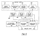
- the former components can be seen as including three major subsystems; a digital subsystem, an analogue subsystem and a power supply subsystem.
- the digital subsystem consists of the controller 12, which includes a 486 DX computer 51, an interface board 52, buffer boards 54 and FIFO boards 56 that cooperate to generate up to 512 channels of square waves with specified phases and amplitudes per duty cycles. While only 512 channels are implemented in the following discussion, it will be understood that additional channels are possible. Each channel is amplified and matched in the analog subsystem to the impedance of the corresponding transducer 20 which will be driven by that channel.
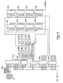
- the interface board 52 is a 4.8 inch by 6.5 inch custom printed circuit (PC) board that is plugged in the appropriate slot of the controller 12. This board 52 serves as an interface between the computer 51 and the buffer boards 54 and FIFO boards 56 which are located in a card cage 58.
- PC printed circuit
- two latches 100 and 102, latch the I/O data bus from the computer.
- One of eight decoders, 104 inputs three address lines, A1-A3, and decodes eight outputs to select eight 3-input NOR gates 106, 108, 110, 112, 114, 116, 118 and 120.
- the outputs of the NOR gates connect to the chip_ select inputs of eight output latches 122, 124, 126, 128, 130, 132, 134, 136, four of which 122, 124, 126, 128 are used to latch the 32-bit data bus, D0-D31, three 130, 132, 134 to a latch the 24-bit address bus, A0-A23, (only part of them are use in this system) and one 136 to latch 8-bit control bus comprising: OE_, RS_, REN_, WEN_, CLKEN_, CLKSEL, PLSCTRL_, FBCTRL_, where:
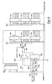
- the buffer boards 54 buffer the data bus, the clock and the control bus going to the FIFO boards 56.
- Each buffer board 54 can drive up to eight FIFO boards 56. But in the present system, for design convenience, one buffer board 54 is used to drive two FIFO boards 56.
- One decoder of sixteen, 140 inputs four address lines, A1-A4, and outputs a 16-bit BOARD ENABLE bus. Each output enables one FIFO board 56 when writing data into the Parallel SyncFIFOs. Address lines A4 and A5 are used to chip_select the decoder 140.
- the buffer boards 54 also generate and buffer the clock.
- the original clock source can be provided in two ways. One is to use a crystal oscillator 142 on the board 54 and the other way is to input an external clock signal 144 from a signal generator. A switch, 146, on board 54 allows the user to select either.
- the clock generation circuit is made up of two inverters, 148 and 150, one D flip-flop, 152, one 2-input multiplexer, 154 and one AND gate, 156. Two kinds of clock signals need to be generated. The first is a lower frequency dock signal used when writing the data into the Parallel SyncFIFOs. In this case, the CLKSEL 158 is high (1) and the output of the multiplexer 154 is the same as the STROBE signal 160.
- the output of the dock generation circuit 164 is equal to the STROBE signal 160, i.e. low frequency clock.
- the other clock signal is a high frequency clock used when the Parallel SyncFIFOs are outputting the data.
- the CLKSEL 158 is low (0) and output of multiplexer 154 is the same as original clock source, either the external source 144 or the internal source 142.
- the output of the dock generation circuit 164 is equal to the original clock source, i.e. high frequency dock. In either case, as long as the CLKEN_ signal 162 is disabled (high, 1), the output of the clock generation circuit 164 is low (0).
- each buffer board 54 receives the clock signal from the master board 54.
- a switch 166 on each buffer board allows the user to specify the board as a master or slave board.
- Six 8-bit buffers 168, 170, 172, 174, 176 and 178 are pnavided on the buffer board 54.
- A6 and A7 originate from the address bus and are used as control lines for the FIFO boards 56.
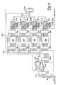
- the FIFO boards 56 are generally responsible for waveform generation and each board is constructed to generate 32 channels of square wave with specified phases and magnitudes (duty cycles). Each channel, after being amplified and matched to the impedance of its corresponding array transducer 20, will drive that particular transducer 20 of the array 16.
- the specified phase and magnitude data are stored in the Parallel SyncFIFOs and each square wave is generated by repeatedly reading this data from the Parallel SyncFIFOs.
- each FIFO board 56 consists of four 512X8-bit Parallel SyncFIFOs, 180, 182, 184 and 186, with four 8-bit input buffers, 188, 190, 192 and 194 and four 8-bit output latches, 196, 198, 200 and 202, some control logic and some feedback logic.
- the control logic is made up of four 2-input NAND gates, 204, 206, 208 and 210, and two 8-bit latches, 212 and 214.
- A6 mentioned above, serves as a control line to control the output. enable of the four 8-bit input buffers, 188, 190, 192 and 194, i.e. when A6 is high (1) and the BOARD_ENABLE line 216 is enabled (low, 0), the output_ enables of the four input buffers 188, 190, 192 and 194 are activated (low, 0) so that data can flow into the buffers.
- A7 serves as an all channel control line. This is used when finishing writing data into all the Parallel SyncFIFOs 180, 182, 184 and 186 and all the Parallel SyncFIFOs 180, 182, 184 and 186 need to start outputting data at the same time.
- its BOARD_ENABLE line 216 is activated (low, 0) and A7 has no effect regardless of its status.
- each FIFO board 56 includes the four 512X8-bit Parallel SyncFIFOs, 180, 182, 184 and 186; the four 8-bit input buffers, 188, 190, 192 and 194; and the four 8-bit output latches 196, 198, 200 and 202, which cooperate to generate 32 channels of square waves, simultaneously.
- the input buffers 188, 190, 192 and 194 buffer the data prior to the Parallel SyncFIFOs 180, 182, 184 and 186 and output latches 196, 198, 200 and 202 latch the output data from the Parallel SyncFIFOs 180, 182, 184 and 186.
- the value of number FL is specified so that, using 48MHz as the original clock source, the frequency range of the square waves generated is 93.75KHz to 1.5MHz.
- the square waves are generated as follows. First, write one complete waveform with specified phases and amplitudes into the four Parallel SyncFIFO 180, 182, 184 and 186 on board #0, i.e. FL words. At this moment, the write_ pointer of the each Parallel SyncFIFO is located FL while the read_pointer remains at location 0. Second, do the same procedure for all the other boards until the Parallel SyncFIFOs on each FIFO board 56 is written in one complete waveform. Third, start all channel control action (all BOARD_ENABLE lines 214 high, A7 low) and let all FIFOs 56 start synchronous reading and writing so the FIFOs 56 repeat reading and writing the same waveform data and output continuous square waves.
- Feedback logic is used as a self-test circuit for FIFO boards 56. Prior to using the FIFO boards, data is written into the Parallel SyncFIFOs 180, 182, 184 and 186 and, by checking the internal feedback signals, we can tell if the FIFO boards 56 are properly functioning.
- the feedback logic includes four 8-input NAND gates, 218, 220, 222, 224, 32 pull-up resistors 228 through 292 and one feedback buffer, 294. Each NAND gate inputs, through nine corresponding output latches, the outputs of each Parallel SyncFIFO to the feedback buffer 294. By initially writing all 1's into the Parallel SyncFIFOs 180, 182, 184 and 186, if the feedback signals are 0, it means that the FIFO boards 56 are working properly.
- the digital subsystem needs only a +5v power supply 58.
- the output square wave has a magnitude (note: this is different from the duty cycle) of 5v and a wide frequency range.
- the analog subsystem contains the amplifier boards 60 and the matching boards 62, which respectively amplify the square waves generated by the digital subsystem and match them to the impedance of the array's individual transducers 20.
- Each amplifier board 62 contains the power drivers 296 and 298, as well as short circuit protection circuit 300, and each board drives sixteen channels of the array 16.
- the output of the boards 62 is driven by a pair of N-channel MOSFETs IRF510 transistors 296 and 298.
- a short circuit protection circuit 300 cuts the main DC supply 66 current (to the corresponding pair of channels) to a low (i.e. safe) level.
- an LEDs on the backplane board can be provided to light up, indicating a short circuit presence on the corresponding amplifier board's output.
- resistors 302 and 304 are 302 and 304 accordingly provided.
- the maximum voltage must be established such that a amplifier board 62 will supply 10 watts (or less) per transducer 20 (on average) at the maximum voltage per the table below: Max. volt. R1 (302) Rp(304) 40 82K 2.7K, 3W 50 120K 3.3K, 3W 60 270K 4K, 3W 70 680K 5.6K, 3W
- the circuitry of the amplifier boards 62 converts the Transistor - Transistor Logic (TTL) level digital control signal to a level which is high enough to drive the piezoelectric transducers 20 of the array 16.
- TTL Transistor - Transistor Logic
- Two opposite TTL signals 306 and 308 are the inputs to the MOSFET driver 310, which converts the signals into two opposite CMOS level (0-15 v) signals 313 and 314. These signals drive the gates of the two MOSFET power transistors 296 and 298 that compose the output stage of the amplifier circuit as a class E amplifier.
- the two transistors 296 and 298 should not be allowed to be ON simultaneously. If both transistors are ON, an effective short circuit occurs between the DC power supply 66 and the ground, with only fractions of 1 ⁇ (transistors drain-source on-state resistors) in the way. This short circuit lowers the efficiency of the amplifier and heats up the transistors 296 and 298.
- the MOSFET drivers have a turn on delay that is 25 ns. longer than the tum off delay.
- the transistors tum off delay is ⁇ 25 ns.
- each gate of the transistors are driven through a parallel circuit of a diode 316 and 318 and a 20 ⁇ resistor 320 and 322. Accordingly, this circuit provides a one-way delay.
- the resistors 320 and 322 increase the RC time constant of the corresponding transistor gate, this causes some delay in the turn-on time, but does not effect the turn-off time due to the negligible forward resistance of the diodes 316 and 318.
- Heat sinks are used with the transistors 296 and 298 to help dissipating any excessive heat.
- Short circuit protection in the amplifier boards 60 consist of a power p-n-p transistor 324 a small signal n-p-n transistor 326 and three resistors 302, 304 and 328.
- the p-n-p transistor 324 limits the main DC supply 66 current, which is always ON under normal running conditions.
- the base current of the p-n-p transistor 324 is sunk through the collector of the n-p-n transistor 326.
- the p-n-p transistor 324 turns OFF, because the n-p-n transistor 326 cannot sink the required base current of the p-n-p transistor 324.
- This current is controlled by power (Rp) resistor 304 between the emitter of the n-p-n transistor 326 and the ground 330.
- Matching boards 64 are coupled between the amplifier boards 62 and the array 16.
- the matching boards 64 are used to match the impedance of the transducers 20 with their respective square wave signals. Since the impedance of transducers 20 has capacitance part, the matching boards 64 are designated to have inductance part. This is so that the overall impedance of the load to amplifiers tends to pure resistance.
- Each matching board 64 has sixteen channels and the basic circuit 70 for each channel is as shown in FIG. 8.
- the circuit 332 is made up of a 0.1 ⁇ , 100V capacitor 334, a custom-wound inductor 336 and a custom-wound transformer 338.
- the primary-to-secondary ratio of the transformer 338 is decided according to the impedance of the transducers 20. Once the transformer 338 has been chosen, user can adjust the turns of the indicator to make best match. In the presently described system, the ratio of the transformers was 1:2 to 1:4.
Landscapes
- Health & Medical Sciences (AREA)
- Life Sciences & Earth Sciences (AREA)
- Surgery (AREA)
- Nuclear Medicine, Radiotherapy & Molecular Imaging (AREA)
- Engineering & Computer Science (AREA)
- Medical Informatics (AREA)
- Animal Behavior & Ethology (AREA)
- Orthopedic Medicine & Surgery (AREA)
- Biomedical Technology (AREA)
- Heart & Thoracic Surgery (AREA)
- Veterinary Medicine (AREA)
- Molecular Biology (AREA)
- Vascular Medicine (AREA)
- General Health & Medical Sciences (AREA)
- Public Health (AREA)
- Mechanical Engineering (AREA)
- Radiology & Medical Imaging (AREA)
- Ultra Sonic Daignosis Equipment (AREA)
- Transducers For Ultrasonic Waves (AREA)
- Surgical Instruments (AREA)
Claims (11)
- Ultraschallsystem (10) zum Durchführen einer Herzablation an einem Patienten (28), wobei das Ultraschallsystem (10) aufweist:Eine Anordnung (16) zur externen Positionierung relativ zum Körper des Patienten (28), wobei die Anordnung (16) mehrere Ultraschallwandler (20) aufweist, die dazu ausgelegt sind, Ultraschallenergie in Form eines fokussierten Ultraschall-Strahls (22) zu erzeugen, wobei der Strahl (22) ausreichend Energie aufweist, um ein vorbestimmtes Herzgewebevolumen (24) des Patienten (28) abzutragen;eine Lokalisierungseinrichtung (42) zum Identifizieren und Lokalisieren des vorbestimmten Behandlungsvolumens, an welchem die Herzablation durchgeführt werden soll;eine Steuereinrichtung (12) zum Erzeugen von phasengesteuerten elektrischen Steuersignalen zum Steuern der Erzeugung von phasengesteuerten Ultraschallwellen durch einzelne der Wandler (20), wobei die Ultraschallwellen zur Bildung des Strahl (22) zusammenwirken;eine Treibereinrichtung (14), die mit der Steuereinrichtung (12) und mit den Wandlern (20) verbunden ist, um die Wandler (20) zu treiben, wobei die Treibereinrichtung (14) die Steuersignale verstärkt und einzelne Kanäle von phasengesteuertem elektrischen Strom erzeugt, wobei der elektrische Strom an einzelne der Wandler (20) in Übereinstimmung mit Steuersignalen angelegt wird; undeine Fokuskorrektureinrichtung (18) zum Fokussieren des Strahls (22) nach seiner Defokussierung durch akustische Aberrationen, die aus inhomogenem Gewebe (30, 32, 34, 36) zwischen der Anordnung (16) und dem vorbestimmten Herzgewebevolumen (24) resultieren, wobei die Fokuskorrektureinrichtung (18) eine Sensoreinrichtung (44) zum Erfassen der Wellen aufweist, die durch die Wandler (20) erzeugt werden, nachdem die Wellen auf die Aberrationen getroffen sind, wobei die Sensoreinrichtung (44) mit der Steuereinrichtung (12) verbunden ist und ihre Kopplungssignale bereitstellt, die die Aberrationen anzeigen, wobei die Steuereinrichtung (12) Kompensationssteuersignale für die Antriebseinrichtung (14) ermittelt und kommuniziert, welche die Wandler (20) in Reaktion hierauf derart treiben, dass ein refokussierter Strahl (23) auf dem vorbestimmten Herzgewebevolumen (24) erzeugt und gebildet wird, wodurch die akustischen Aberrationen kompensiert werden und eine Herzablation durchgeführt werden kann.
- Ultraschallsystem nach Anspruch 1, wobei die Fokuskorrektureinrichtung (18) einen Katheder (46) und zumindest einen darauf getragenen Sensor (44) umfasst, wobei der Katheder (46) ein proximales Ende und ein distales Ende aufweist, wobei das distale Ende zur Einführung in das Herz (26) des Patienten (28) im wesentlichen benachbart zu dem vorbestimmten Herzgewebevolumen (24) ausgelegt ist.
- Ultraschallsystem nach Anspruch 2, wobei der Sensor (44) dazu ausgelegt ist, eine Phasenverteilung der Wellen zu erfassen, nachdem diese auf die akustischen Aberrationen betroffen sind, wobei der Sensor (44) außerdem mit der Steuereinrichtung (12) verbunden ist, um Aberrationsrückkopplungssignale bereitzustellen, welche die Phasenverteilung des defokussierten Strahls (48) anzeigen.
- Ultraschallsystem nach Anspruch 3, wobei die Steuereinrichtung (12) dazu ausgelegt ist, die Aberrationsrückkopplungssignale zu empfangen, eine kompensierende Treiberphasen-Verteilung zu ermitteln und Kompensationssteuersignale zu erzeugen, die der Treibereinrichtung (14) kommuniziert werden, wobei die Treibereinrichtung (14) daraufhin die Wandler (20) in Übereinstimmung mit den Kompensationssteuersignalen derart treibt, dass Ultraschallwellen erzeugt werden, welche die Aberrationen kompensieren und den refokussierten Strahl (22) auf den vorbestimmten Herzgewebevolumen (24) erzeugen.
- Ultraschallsystem nach Anspruch 2, wobei die Fokuskorrektureinrichtung (18) mehrere Sensoren (44) umfasst.
- Ultraschallsystem nach Anspruch 2, wobei der Sensor (44) ein Hydrophonsensor (44) ist.
- Ultraschallsystem nach Anspruch 1, wobei die Fokuskorrektureinrichtung (18) einen in den Patienten (28) eingeführten Sensor (44) umfasst.
- Ultraschallsystem nach Anspruch 1, wobei die Fokuskorrektureinrichtung (18) dazu ausgelegt ist, außerhalb des Patienten (28) angelegt zu werden, und wobei das System (10) insgesamt nicht invasiv ist.
- Ultraschallsystem nach Anspruch 8, wobei die Fokuskorrektureinrichtung (18) ein Ultraschallerfassungseinrichtung (44) zum Erfassen eines reflektierten Teils des Strahls (22) umfasst, der durch die akustischen Aberrationen hervorgerufen ist.
- Ultraschallsystem nach Anspruch 8, wobei die Fokuskorrektureinrichtung (18) ein Ultraschallerfassungseinrichtung (44) zum Erfassen des Strahls aufweist, nachdem der Strahl auf die akustischen Aberrationen getroffen ist.
- Ultraschallsystem nach einem der Ansprüche 1 bis 10, wobei die Fokuskorrektureinrichtung (18) außerdem zum Refokussieren des Strahls auf dem vorbestimmten Herzgewebevolumen (24) genutzt wird, und der Strahl einer Bewegung des vorbestimmten Herzgewebevolumens (24) während der Durchführung der Ablation folgt.
Applications Claiming Priority (3)
| Application Number | Priority Date | Filing Date | Title |
|---|---|---|---|
| US08/554,134 US5590657A (en) | 1995-11-06 | 1995-11-06 | Phased array ultrasound system and method for cardiac ablation |
| US554134 | 1995-11-06 | ||
| PCT/US1996/016928 WO1997017693A1 (en) | 1995-11-06 | 1996-10-22 | Phased array ultrasound system and method for cardiac ablation |
Publications (2)
| Publication Number | Publication Date |
|---|---|
| EP0860004A1 EP0860004A1 (de) | 1998-08-26 |
| EP0860004B1 true EP0860004B1 (de) | 2003-01-08 |
Family
ID=24212180
Family Applications (1)
| Application Number | Title | Priority Date | Filing Date |
|---|---|---|---|
| EP96936845A Expired - Lifetime EP0860004B1 (de) | 1995-11-06 | 1996-10-22 | Phasengesteuerter ultraschall wandlerreihesystem für intrakardielle ablation |
Country Status (6)
| Country | Link |
|---|---|
| US (1) | US5590657A (de) |
| EP (1) | EP0860004B1 (de) |
| JP (1) | JP3853368B2 (de) |
| AU (1) | AU7466896A (de) |
| DE (1) | DE69625700T2 (de) |
| WO (1) | WO1997017693A1 (de) |
Cited By (2)
| Publication number | Priority date | Publication date | Assignee | Title |
|---|---|---|---|---|
| EP1591070A1 (de) * | 2004-04-26 | 2005-11-02 | Armando Salle | Verfahren und Gerät zur Erzeugung von Schockwellen mit einstellbarem Fokus |
| EP4230262A3 (de) * | 2015-06-24 | 2023-11-22 | The Regents Of The University Of Michigan | System für histotripsietherapie zur behandlung des hirngewebes |
Families Citing this family (295)
| Publication number | Priority date | Publication date | Assignee | Title |
|---|---|---|---|---|
| US6161543A (en) | 1993-02-22 | 2000-12-19 | Epicor, Inc. | Methods of epicardial ablation for creating a lesion around the pulmonary veins |
| US6409722B1 (en) | 1998-07-07 | 2002-06-25 | Medtronic, Inc. | Apparatus and method for creating, maintaining, and controlling a virtual electrode used for the ablation of tissue |
| US5897553A (en) | 1995-11-02 | 1999-04-27 | Medtronic, Inc. | Ball point fluid-assisted electrocautery device |
| AU1616797A (en) * | 1996-02-15 | 1997-09-02 | Victor Spivak | Multi-element energy focusing |
| IL119137A0 (en) * | 1996-02-15 | 1996-11-14 | Biosense Ltd | Intrabody energy focusing |
| NL1003024C2 (nl) * | 1996-05-03 | 1997-11-06 | Tjong Hauw Sie | Prikkelgeleidingsblokkeringsinstrument. |
| WO1998007373A1 (en) * | 1996-08-21 | 1998-02-26 | Brigham & Women's Hospital | Methods and apparatus for delivery of noninvasive ultrasound brain therapy through intact skull |
| US6840936B2 (en) * | 1996-10-22 | 2005-01-11 | Epicor Medical, Inc. | Methods and devices for ablation |
| US6719755B2 (en) * | 1996-10-22 | 2004-04-13 | Epicor Medical, Inc. | Methods and devices for ablation |
| US7052493B2 (en) * | 1996-10-22 | 2006-05-30 | Epicor Medical, Inc. | Methods and devices for ablation |
| US6311692B1 (en) * | 1996-10-22 | 2001-11-06 | Epicor, Inc. | Apparatus and method for diagnosis and therapy of electrophysiological disease |
| US6805128B1 (en) * | 1996-10-22 | 2004-10-19 | Epicor Medical, Inc. | Apparatus and method for ablating tissue |
| US20040260278A1 (en) * | 1996-10-22 | 2004-12-23 | Anderson Scott C. | Apparatus and method for ablating tissue |
| US6096037A (en) * | 1997-07-29 | 2000-08-01 | Medtronic, Inc. | Tissue sealing electrosurgery device and methods of sealing tissue |
| US6490474B1 (en) | 1997-08-01 | 2002-12-03 | Cardiac Pathways Corporation | System and method for electrode localization using ultrasound |
| SE9703543D0 (sv) * | 1997-09-30 | 1997-09-30 | Siemens Elema Ab | Radiation delivery system |
| US8709007B2 (en) | 1997-10-15 | 2014-04-29 | St. Jude Medical, Atrial Fibrillation Division, Inc. | Devices and methods for ablating cardiac tissue |
| US6385474B1 (en) * | 1999-03-19 | 2002-05-07 | Barbara Ann Karmanos Cancer Institute | Method and apparatus for high-resolution detection and characterization of medical pathologies |
| US6706039B2 (en) | 1998-07-07 | 2004-03-16 | Medtronic, Inc. | Method and apparatus for creating a bi-polar virtual electrode used for the ablation of tissue |
| US6537248B2 (en) | 1998-07-07 | 2003-03-25 | Medtronic, Inc. | Helical needle apparatus for creating a virtual electrode used for the ablation of tissue |
| US6950689B1 (en) | 1998-08-03 | 2005-09-27 | Boston Scientific Scimed, Inc. | Dynamically alterable three-dimensional graphical model of a body region |
| US8308719B2 (en) * | 1998-09-21 | 2012-11-13 | St. Jude Medical, Atrial Fibrillation Division, Inc. | Apparatus and method for ablating tissue |
| US6208881B1 (en) | 1998-10-20 | 2001-03-27 | Micropure Medical, Inc. | Catheter with thin film electrodes and method for making same |
| US6245062B1 (en) * | 1998-10-23 | 2001-06-12 | Afx, Inc. | Directional reflector shield assembly for a microwave ablation instrument |
| US7844319B2 (en) * | 1998-11-04 | 2010-11-30 | Susil Robert C | Systems and methods for magnetic-resonance-guided interventional procedures |
| US8244370B2 (en) * | 2001-04-13 | 2012-08-14 | Greatbatch Ltd. | Band stop filter employing a capacitor and an inductor tank circuit to enhance MRI compatibility of active medical devices |
| US6701176B1 (en) | 1998-11-04 | 2004-03-02 | Johns Hopkins University School Of Medicine | Magnetic-resonance-guided imaging, electrophysiology, and ablation |
| US6755821B1 (en) | 1998-12-08 | 2004-06-29 | Cardiocavitational Systems, Inc. | System and method for stimulation and/or enhancement of myocardial angiogenesis |
| US6309355B1 (en) | 1998-12-22 | 2001-10-30 | The Regents Of The University Of Michigan | Method and assembly for performing ultrasound surgery using cavitation |
| US7226446B1 (en) | 1999-05-04 | 2007-06-05 | Dinesh Mody | Surgical microwave ablation assembly |
| US6277113B1 (en) * | 1999-05-28 | 2001-08-21 | Afx, Inc. | Monopole tip for ablation catheter and methods for using same |
| AU2007254588B2 (en) * | 1999-07-19 | 2010-02-11 | St. Jude Medical, Atrial Fibrillation Division, Inc. | Apparatus and method for ablating tissue |
| US20070282324A1 (en) * | 1999-07-19 | 2007-12-06 | Matthias Vaska | Apparatus and method for diagnosis and therapy of electrophysiological disease |
| AU775394B2 (en) * | 1999-07-19 | 2004-07-29 | St. Jude Medical, Atrial Fibrillation Division, Inc. | Apparatus and method for ablating tissue |
| WO2001034018A2 (en) * | 1999-10-25 | 2001-05-17 | Therus Corporation | Use of focused ultrasound for vascular sealing |
| US6626855B1 (en) * | 1999-11-26 | 2003-09-30 | Therus Corpoation | Controlled high efficiency lesion formation using high intensity ultrasound |
| US7033352B1 (en) | 2000-01-18 | 2006-04-25 | Afx, Inc. | Flexible ablation instrument |
| US7706882B2 (en) * | 2000-01-19 | 2010-04-27 | Medtronic, Inc. | Methods of using high intensity focused ultrasound to form an ablated tissue area |
| US6595934B1 (en) * | 2000-01-19 | 2003-07-22 | Medtronic Xomed, Inc. | Methods of skin rejuvenation using high intensity focused ultrasound to form an ablated tissue area containing a plurality of lesions |
| US8241274B2 (en) | 2000-01-19 | 2012-08-14 | Medtronic, Inc. | Method for guiding a medical device |
| US6692450B1 (en) * | 2000-01-19 | 2004-02-17 | Medtronic Xomed, Inc. | Focused ultrasound ablation devices having selectively actuatable ultrasound emitting elements and methods of using the same |
| US8221402B2 (en) * | 2000-01-19 | 2012-07-17 | Medtronic, Inc. | Method for guiding a medical device |
| US6447443B1 (en) | 2001-01-13 | 2002-09-10 | Medtronic, Inc. | Method for organ positioning and stabilization |
| US8048070B2 (en) | 2000-03-06 | 2011-11-01 | Salient Surgical Technologies, Inc. | Fluid-assisted medical devices, systems and methods |
| US8083736B2 (en) | 2000-03-06 | 2011-12-27 | Salient Surgical Technologies, Inc. | Fluid-assisted medical devices, systems and methods |
| ATE408436T1 (de) * | 2000-03-24 | 2008-10-15 | Prorhythm Inc | Gerät zur intrakorporalen thermotherapie |
| US6673068B1 (en) * | 2000-04-12 | 2004-01-06 | Afx, Inc. | Electrode arrangement for use in a medical instrument |
| US6613004B1 (en) | 2000-04-21 | 2003-09-02 | Insightec-Txsonics, Ltd. | Systems and methods for creating longer necrosed volumes using a phased array focused ultrasound system |
| US6554826B1 (en) | 2000-04-21 | 2003-04-29 | Txsonics-Ltd | Electro-dynamic phased array lens for controlling acoustic wave propagation |
| US6419648B1 (en) | 2000-04-21 | 2002-07-16 | Insightec-Txsonics Ltd. | Systems and methods for reducing secondary hot spots in a phased array focused ultrasound system |
| US6543272B1 (en) | 2000-04-21 | 2003-04-08 | Insightec-Txsonics Ltd. | Systems and methods for testing and calibrating a focused ultrasound transducer array |
| US6488680B1 (en) | 2000-04-27 | 2002-12-03 | Medtronic, Inc. | Variable length electrodes for delivery of irrigated ablation |
| WO2001082811A1 (en) * | 2000-04-27 | 2001-11-08 | Medtronic, Inc. | System and method for assessing transmurality of ablation lesions |
| US6514250B1 (en) * | 2000-04-27 | 2003-02-04 | Medtronic, Inc. | Suction stabilized epicardial ablation devices |
| DE60111517T2 (de) | 2000-04-27 | 2006-05-11 | Medtronic, Inc., Minneapolis | Vibrationsempfindliche ablationsvorrichtung |
| US6506171B1 (en) | 2000-07-27 | 2003-01-14 | Insightec-Txsonics, Ltd | System and methods for controlling distribution of acoustic energy around a focal point using a focused ultrasound system |
| US6612988B2 (en) | 2000-08-29 | 2003-09-02 | Brigham And Women's Hospital, Inc. | Ultrasound therapy |
| US6926669B1 (en) * | 2000-10-10 | 2005-08-09 | Medtronic, Inc. | Heart wall ablation/mapping catheter and method |
| US6508764B1 (en) | 2000-10-31 | 2003-01-21 | Koninklijke Philips Electronics N.V. | Aberration correction apparatus and methods |
| US6666833B1 (en) * | 2000-11-28 | 2003-12-23 | Insightec-Txsonics Ltd | Systems and methods for focussing an acoustic energy beam transmitted through non-uniform tissue medium |
| US6506154B1 (en) * | 2000-11-28 | 2003-01-14 | Insightec-Txsonics, Ltd. | Systems and methods for controlling a phased array focused ultrasound system |
| US6618620B1 (en) | 2000-11-28 | 2003-09-09 | Txsonics Ltd. | Apparatus for controlling thermal dosing in an thermal treatment system |
| US6770031B2 (en) | 2000-12-15 | 2004-08-03 | Brigham And Women's Hospital, Inc. | Ultrasound therapy |
| US20020087151A1 (en) | 2000-12-29 | 2002-07-04 | Afx, Inc. | Tissue ablation apparatus with a sliding ablation instrument and method |
| US7740623B2 (en) * | 2001-01-13 | 2010-06-22 | Medtronic, Inc. | Devices and methods for interstitial injection of biologic agents into tissue |
| US20040138621A1 (en) * | 2003-01-14 | 2004-07-15 | Jahns Scott E. | Devices and methods for interstitial injection of biologic agents into tissue |
| US7628780B2 (en) * | 2001-01-13 | 2009-12-08 | Medtronic, Inc. | Devices and methods for interstitial injection of biologic agents into tissue |
| US8457760B2 (en) | 2001-04-13 | 2013-06-04 | Greatbatch Ltd. | Switched diverter circuits for minimizing heating of an implanted lead and/or providing EMI protection in a high power electromagnetic field environment |
| US8989870B2 (en) * | 2001-04-13 | 2015-03-24 | Greatbatch Ltd. | Tuned energy balanced system for minimizing heating and/or to provide EMI protection of implanted leads in a high power electromagnetic field environment |
| US8977355B2 (en) | 2001-04-13 | 2015-03-10 | Greatbatch Ltd. | EMI filter employing a capacitor and an inductor tank circuit having optimum component values |
| US20070088416A1 (en) * | 2001-04-13 | 2007-04-19 | Surgi-Vision, Inc. | Mri compatible medical leads |
| US8509913B2 (en) * | 2001-04-13 | 2013-08-13 | Greatbatch Ltd. | Switched diverter circuits for minimizing heating of an implanted lead and/or providing EMI protection in a high power electromagnetic field environment |
| CA2482202C (en) | 2001-04-13 | 2012-07-03 | Surgi-Vision, Inc. | Systems and methods for magnetic-resonance-guided interventional procedures |
| US8600519B2 (en) * | 2001-04-13 | 2013-12-03 | Greatbatch Ltd. | Transient voltage/current protection system for electronic circuits associated with implanted leads |
| US8219208B2 (en) * | 2001-04-13 | 2012-07-10 | Greatbatch Ltd. | Frequency selective passive component networks for active implantable medical devices utilizing an energy dissipating surface |
| US9295828B2 (en) | 2001-04-13 | 2016-03-29 | Greatbatch Ltd. | Self-resonant inductor wound portion of an implantable lead for enhanced MRI compatibility of active implantable medical devices |
| US6663627B2 (en) | 2001-04-26 | 2003-12-16 | Medtronic, Inc. | Ablation system and method of use |
| US7959626B2 (en) | 2001-04-26 | 2011-06-14 | Medtronic, Inc. | Transmural ablation systems and methods |
| US6699240B2 (en) * | 2001-04-26 | 2004-03-02 | Medtronic, Inc. | Method and apparatus for tissue ablation |
| US6807968B2 (en) * | 2001-04-26 | 2004-10-26 | Medtronic, Inc. | Method and system for treatment of atrial tachyarrhythmias |
| US6648883B2 (en) * | 2001-04-26 | 2003-11-18 | Medtronic, Inc. | Ablation system and method of use |
| US7250048B2 (en) | 2001-04-26 | 2007-07-31 | Medtronic, Inc. | Ablation system and method of use |
| US7211044B2 (en) * | 2001-05-29 | 2007-05-01 | Ethicon Endo-Surgery, Inc. | Method for mapping temperature rise using pulse-echo ultrasound |
| US7846096B2 (en) | 2001-05-29 | 2010-12-07 | Ethicon Endo-Surgery, Inc. | Method for monitoring of medical treatment using pulse-echo ultrasound |
| US20030032898A1 (en) * | 2001-05-29 | 2003-02-13 | Inder Raj. S. Makin | Method for aiming ultrasound for medical treatment |
| US6845260B2 (en) * | 2001-07-18 | 2005-01-18 | Koninklijke Philips Electronics N.V. | Automatic vessel indentification for angiographic screening |
| FR2831743B1 (fr) * | 2001-10-25 | 2004-01-30 | Cit Alcatel | Systeme de routage is-is tolerant aux fautes et procede correspondant |
| US6656175B2 (en) * | 2001-12-11 | 2003-12-02 | Medtronic, Inc. | Method and system for treatment of atrial tachyarrhythmias |
| US7099717B2 (en) | 2002-01-03 | 2006-08-29 | Afx Inc. | Catheter having improved steering |
| US6827715B2 (en) * | 2002-01-25 | 2004-12-07 | Medtronic, Inc. | System and method of performing an electrosurgical procedure |
| US7967816B2 (en) | 2002-01-25 | 2011-06-28 | Medtronic, Inc. | Fluid-assisted electrosurgical instrument with shapeable electrode |
| US20080275439A1 (en) * | 2002-01-25 | 2008-11-06 | David Francischelli | Cardiac ablation and electrical interface system and instrument |
| US7192427B2 (en) * | 2002-02-19 | 2007-03-20 | Afx, Inc. | Apparatus and method for assessing transmurality of a tissue ablation |
| US20050075629A1 (en) * | 2002-02-19 | 2005-04-07 | Afx, Inc. | Apparatus and method for assessing tissue ablation transmurality |
| US7118566B2 (en) | 2002-05-16 | 2006-10-10 | Medtronic, Inc. | Device and method for needle-less interstitial injection of fluid for ablation of cardiac tissue |
| US7294143B2 (en) * | 2002-05-16 | 2007-11-13 | Medtronic, Inc. | Device and method for ablation of cardiac tissue |
| WO2003102614A1 (en) | 2002-05-29 | 2003-12-11 | Surgi-Vision, Inc. | Magnetic resonance probes |
| EP1521549A2 (de) * | 2002-06-27 | 2005-04-13 | UC-Care Ltd. | Verfahren und vorrichtung zur positionierung eines chirurgischen instrumentes |
| AU2003257562A1 (en) * | 2002-08-26 | 2004-05-04 | Yoshifumi Fujinaka | Focusing powerful ultrasonic therapeutic device |
| US7083620B2 (en) * | 2002-10-30 | 2006-08-01 | Medtronic, Inc. | Electrosurgical hemostat |
| US7156816B2 (en) * | 2002-11-26 | 2007-01-02 | Biosense, Inc. | Ultrasound pulmonary vein isolation |
| US8088067B2 (en) * | 2002-12-23 | 2012-01-03 | Insightec Ltd. | Tissue aberration corrections in ultrasound therapy |
| US6889695B2 (en) | 2003-01-08 | 2005-05-10 | Cyberheart, Inc. | Method for non-invasive heart treatment |
| US7201749B2 (en) * | 2003-02-19 | 2007-04-10 | Biosense, Inc. | Externally-applied high intensity focused ultrasound (HIFU) for pulmonary vein isolation |
| US20040162507A1 (en) | 2003-02-19 | 2004-08-19 | Assaf Govari | Externally-applied high intensity focused ultrasound (HIFU) for therapeutic treatment |
| US7497857B2 (en) * | 2003-04-29 | 2009-03-03 | Medtronic, Inc. | Endocardial dispersive electrode for use with a monopolar RF ablation pen |
| US7112196B2 (en) * | 2003-06-13 | 2006-09-26 | Piezo Technologies, Inc. | Multi-element array for acoustic ablation |
| US7670335B2 (en) | 2003-07-21 | 2010-03-02 | Biosense Webster, Inc. | Ablation device with spiral array ultrasound transducer |
| US7247269B2 (en) * | 2003-07-21 | 2007-07-24 | Biosense Webster, Inc. | Method for making a spiral array ultrasound transducer |
| US20050080469A1 (en) * | 2003-09-04 | 2005-04-14 | Larson Eugene A. | Treatment of cardiac arrhythmia utilizing ultrasound |
| US20050165298A1 (en) * | 2003-09-04 | 2005-07-28 | Crum, Kaminski & Larson, Llc | Treatment of cardiac tissue following myocardial infarction utilizing high intensity focused ultrasound |
| US20050209588A1 (en) * | 2003-09-04 | 2005-09-22 | Crum, Kaminski & Larson, Llc | HIFU resculpturing and remodeling of heart valves |
| US20050149008A1 (en) * | 2003-09-04 | 2005-07-07 | Crum, Kaminski & Larson, Llc | Treatment of cardiac arrhythmia utilizing ultrasound |
| US20050059448A1 (en) * | 2003-09-11 | 2005-03-17 | Scott Sims | Method and apparatus for playing card game |
| US20050251127A1 (en) * | 2003-10-15 | 2005-11-10 | Jared Brosch | Miniature ultrasonic transducer with focusing lens for intracardiac and intracavity applications |
| US20050171396A1 (en) * | 2003-10-20 | 2005-08-04 | Cyberheart, Inc. | Method for non-invasive lung treatment |
| US7854733B2 (en) * | 2004-03-24 | 2010-12-21 | Biosense Webster, Inc. | Phased-array for tissue treatment |
| US20050228286A1 (en) * | 2004-04-07 | 2005-10-13 | Messerly Jeffrey D | Medical system having a rotatable ultrasound source and a piercing tip |
| US20050240105A1 (en) * | 2004-04-14 | 2005-10-27 | Mast T D | Method for reducing electronic artifacts in ultrasound imaging |
| US20050234438A1 (en) * | 2004-04-15 | 2005-10-20 | Mast T D | Ultrasound medical treatment system and method |
| US20050240124A1 (en) * | 2004-04-15 | 2005-10-27 | Mast T D | Ultrasound medical treatment system and method |
| US7494467B2 (en) * | 2004-04-16 | 2009-02-24 | Ethicon Endo-Surgery, Inc. | Medical system having multiple ultrasound transducers or an ultrasound transducer and an RF electrode |
| US8333764B2 (en) * | 2004-05-12 | 2012-12-18 | Medtronic, Inc. | Device and method for determining tissue thickness and creating cardiac ablation lesions |
| US20060009756A1 (en) * | 2004-05-14 | 2006-01-12 | Francischelli David E | Method and devices for treating atrial fibrillation by mass ablation |
| US20050256405A1 (en) * | 2004-05-17 | 2005-11-17 | Makin Inder Raj S | Ultrasound-based procedure for uterine medical treatment |
| US7883468B2 (en) * | 2004-05-18 | 2011-02-08 | Ethicon Endo-Surgery, Inc. | Medical system having an ultrasound source and an acoustic coupling medium |
| US7951095B2 (en) * | 2004-05-20 | 2011-05-31 | Ethicon Endo-Surgery, Inc. | Ultrasound medical system |
| US20050261587A1 (en) * | 2004-05-20 | 2005-11-24 | Makin Inder R S | Ultrasound medical system and method |
| US7473250B2 (en) * | 2004-05-21 | 2009-01-06 | Ethicon Endo-Surgery, Inc. | Ultrasound medical system and method |
| US20050261588A1 (en) * | 2004-05-21 | 2005-11-24 | Makin Inder Raj S | Ultrasound medical system |
| US20050261571A1 (en) * | 2004-05-21 | 2005-11-24 | Willis Nathaniel P | 3-D ultrasound navigation during radio-frequency ablation |
| ATE516762T1 (de) * | 2004-06-02 | 2011-08-15 | Medtronic Inc | Ablations- und klammerinstrument |
| EP1750606B1 (de) * | 2004-06-02 | 2010-05-05 | Medtronic, Inc. | Zusammengesetzte bipolare ablationsvorrichtung |
| EP1750607A2 (de) * | 2004-06-02 | 2007-02-14 | Medtronic, Inc. | Schlaufenablationsgerät und verfahren |
| EP1750608B1 (de) * | 2004-06-02 | 2012-10-03 | Medtronic, Inc. | Ablationsvorrichtung mit backen |
| US20100145331A1 (en) * | 2004-06-02 | 2010-06-10 | Chrisitian Steven C | Loop Ablation Apparatus and Method |
| US7806839B2 (en) * | 2004-06-14 | 2010-10-05 | Ethicon Endo-Surgery, Inc. | System and method for ultrasound therapy using grating lobes |
| US8409219B2 (en) * | 2004-06-18 | 2013-04-02 | Medtronic, Inc. | Method and system for placement of electrical lead inside heart |
| US8926635B2 (en) * | 2004-06-18 | 2015-01-06 | Medtronic, Inc. | Methods and devices for occlusion of an atrial appendage |
| US8663245B2 (en) | 2004-06-18 | 2014-03-04 | Medtronic, Inc. | Device for occlusion of a left atrial appendage |
| EP1768575B1 (de) * | 2004-06-18 | 2019-01-16 | Medtronic, Inc. | Vorrichtungen zum verschluss eines vorhofanhangs |
| US8409099B2 (en) | 2004-08-26 | 2013-04-02 | Insightec Ltd. | Focused ultrasound system for surrounding a body tissue mass and treatment method |
| US7134543B2 (en) * | 2004-09-22 | 2006-11-14 | Frito-Lay North America, Inc. | Containment apparatus for multi-pass ovens |
| US7833221B2 (en) * | 2004-10-22 | 2010-11-16 | Ethicon Endo-Surgery, Inc. | System and method for treatment of tissue using the tissue as a fiducial |
| US7452357B2 (en) * | 2004-10-22 | 2008-11-18 | Ethicon Endo-Surgery, Inc. | System and method for planning treatment of tissue |
| US20060089626A1 (en) * | 2004-10-22 | 2006-04-27 | Vlegele James W | Surgical device guide for use with an imaging system |
| WO2006069327A2 (en) * | 2004-12-21 | 2006-06-29 | Ebr Systems, Inc. | Implantable transducer devices |
| JP5111116B2 (ja) * | 2004-12-21 | 2012-12-26 | イービーアール システムズ, インコーポレイテッド | ペーシングおよび不整脈処置のためのリード線のない心臓システム |
| US7674256B2 (en) * | 2005-03-17 | 2010-03-09 | Boston Scientific Scimed, Inc. | Treating internal body tissue |
| US20060270900A1 (en) * | 2005-05-26 | 2006-11-30 | Chin Albert K | Apparatus and methods for performing ablation |
| US8932208B2 (en) * | 2005-05-26 | 2015-01-13 | Maquet Cardiovascular Llc | Apparatus and methods for performing minimally-invasive surgical procedures |
| US20070016039A1 (en) | 2005-06-21 | 2007-01-18 | Insightec-Image Guided Treatment Ltd. | Controlled, non-linear focused ultrasound treatment |
| US20070016184A1 (en) * | 2005-07-14 | 2007-01-18 | Ethicon Endo-Surgery, Inc. | Medical-treatment electrode assembly and method for medical treatment |
| US9011473B2 (en) | 2005-09-07 | 2015-04-21 | Ulthera, Inc. | Dissection handpiece and method for reducing the appearance of cellulite |
| EP1928540A4 (de) * | 2005-09-07 | 2010-03-10 | The Foundry Inc | Gerät und verfahren zur unterbrechung von subkutanen strukturen |
| US10548659B2 (en) * | 2006-01-17 | 2020-02-04 | Ulthera, Inc. | High pressure pre-burst for improved fluid delivery |
| US9358033B2 (en) * | 2005-09-07 | 2016-06-07 | Ulthera, Inc. | Fluid-jet dissection system and method for reducing the appearance of cellulite |
| US7967763B2 (en) * | 2005-09-07 | 2011-06-28 | Cabochon Aesthetics, Inc. | Method for treating subcutaneous tissues |
| US9486274B2 (en) | 2005-09-07 | 2016-11-08 | Ulthera, Inc. | Dissection handpiece and method for reducing the appearance of cellulite |
| US8518069B2 (en) | 2005-09-07 | 2013-08-27 | Cabochon Aesthetics, Inc. | Dissection handpiece and method for reducing the appearance of cellulite |
| US8057408B2 (en) | 2005-09-22 | 2011-11-15 | The Regents Of The University Of Michigan | Pulsed cavitational ultrasound therapy |
| US10219815B2 (en) | 2005-09-22 | 2019-03-05 | The Regents Of The University Of Michigan | Histotripsy for thrombolysis |
| US20070083120A1 (en) * | 2005-09-22 | 2007-04-12 | Cain Charles A | Pulsed cavitational ultrasound therapy |
| WO2007039905A2 (en) * | 2005-10-05 | 2007-04-12 | Uc-Care Ltd. | Method and apparatus for positioning a medical instrument |
| US20070233185A1 (en) * | 2005-10-20 | 2007-10-04 | Thomas Anderson | Systems and methods for sealing a vascular opening |
| WO2007085892A2 (en) * | 2005-11-23 | 2007-08-02 | Insightec, Ltd | Hierarchical switching in ultra-high density ultrasound array |
| US7885793B2 (en) | 2007-05-22 | 2011-02-08 | International Business Machines Corporation | Method and system for developing a conceptual model to facilitate generating a business-aligned information technology solution |
| US20080200863A1 (en) * | 2005-12-02 | 2008-08-21 | Cabochon Aesthetics, Inc. | Devices and methods for selectively lysing cells |
| US20080014627A1 (en) * | 2005-12-02 | 2008-01-17 | Cabochon Aesthetics, Inc. | Devices and methods for selectively lysing cells |
| US20080197517A1 (en) * | 2005-12-02 | 2008-08-21 | Cabochon Aesthetics, Inc. | Devices and methods for selectively lysing cells |
| US20080200864A1 (en) * | 2005-12-02 | 2008-08-21 | Cabochon Aesthetics, Inc. | Devices and methods for selectively lysing cells |
| US9248317B2 (en) * | 2005-12-02 | 2016-02-02 | Ulthera, Inc. | Devices and methods for selectively lysing cells |
| US20080195036A1 (en) * | 2005-12-02 | 2008-08-14 | Cabochon Aesthetics, Inc. | Devices and methods for selectively lysing cells |
| US20100191306A1 (en) * | 2006-01-25 | 2010-07-29 | Greatbatch Ltd. | Transient voltage suppression circuit for an implanted rfid chip |
| US20070185479A1 (en) * | 2006-02-06 | 2007-08-09 | Liming Lau | Methods and devices for performing ablation and assessing efficacy thereof |
| US20070225697A1 (en) * | 2006-03-23 | 2007-09-27 | Ketan Shroff | Apparatus and methods for cardiac ablation |
| US8235901B2 (en) * | 2006-04-26 | 2012-08-07 | Insightec, Ltd. | Focused ultrasound system with far field tail suppression |
| US20080039746A1 (en) * | 2006-05-25 | 2008-02-14 | Medtronic, Inc. | Methods of using high intensity focused ultrasound to form an ablated tissue area containing a plurality of lesions |
| US8903505B2 (en) | 2006-06-08 | 2014-12-02 | Greatbatch Ltd. | Implantable lead bandstop filter employing an inductive coil with parasitic capacitance to enhance MRI compatibility of active medical devices |
| US7678109B2 (en) * | 2006-06-23 | 2010-03-16 | St. Jude Medical, Atrial Fibrillation Division, Inc. | Ablation device and method comprising movable ablation elements |
| US20080039879A1 (en) * | 2006-08-09 | 2008-02-14 | Chin Albert K | Devices and methods for atrial appendage exclusion |
| WO2008073994A2 (en) * | 2006-12-12 | 2008-06-19 | Acoustx Corporation | Methods of device spatial registration for multiple-transducer therapeutic ultrasound systems |
| FR2912817B1 (fr) * | 2007-02-21 | 2009-05-22 | Super Sonic Imagine Sa | Procede d'optimisation de la focalisation d'ondes au travers d'un element introducteur d'aberations. |
| US9220837B2 (en) * | 2007-03-19 | 2015-12-29 | Insuline Medical Ltd. | Method and device for drug delivery |
| US20100286467A1 (en) * | 2007-03-19 | 2010-11-11 | Benny Pesach | Device for drug delivery and associated connections thereto |
| US8622991B2 (en) * | 2007-03-19 | 2014-01-07 | Insuline Medical Ltd. | Method and device for drug delivery |
| WO2008114223A1 (en) * | 2007-03-19 | 2008-09-25 | Insuline Medical Ltd. | Drug delivery device |
| US9314298B2 (en) * | 2007-04-17 | 2016-04-19 | St. Jude Medical, Atrial Fibrillation Divisions, Inc. | Vacuum-stabilized ablation system |
| US10201324B2 (en) | 2007-05-04 | 2019-02-12 | Delphinus Medical Technologies, Inc. | Patient interface system |
| NZ582789A (en) | 2007-06-25 | 2012-11-30 | Internat Cardio Corp | Image guided plaque ablation using ultrasound waves |
| WO2009042842A1 (en) | 2007-09-26 | 2009-04-02 | Cyberheart, Inc. | Radiosurgical ablation of the myocardium |
| US8251908B2 (en) | 2007-10-01 | 2012-08-28 | Insightec Ltd. | Motion compensated image-guided focused ultrasound therapy system |
| EP2209517A4 (de) * | 2007-10-05 | 2011-03-30 | Maquet Cardiovascular Llc | Vorrichtungen und verfahren für minimal invasive chirurgische eingriffe |
| US8439940B2 (en) | 2010-12-22 | 2013-05-14 | Cabochon Aesthetics, Inc. | Dissection handpiece with aspiration means for reducing the appearance of cellulite |
| EP2231229A1 (de) | 2007-12-18 | 2010-09-29 | Insuline Medical Ltd. | Wirkstofffreisetzungsvorrichtung mit sensor für geschlossenen kreislauf |
| JP5443386B2 (ja) * | 2007-12-28 | 2014-03-19 | サリエント・サージカル・テクノロジーズ・インコーポレーテッド | 流体支援電気外科デバイス、方法ならびにシステム |
| US20090209986A1 (en) * | 2008-02-15 | 2009-08-20 | Stewart Michael C | Devices, Tools and Methods for Atrial Appendage Exclusion |
| US10080889B2 (en) | 2009-03-19 | 2018-09-25 | Greatbatch Ltd. | Low inductance and low resistance hermetically sealed filtered feedthrough for an AIMD |
| US9108066B2 (en) | 2008-03-20 | 2015-08-18 | Greatbatch Ltd. | Low impedance oxide resistant grounded capacitor for an AIMD |
| US7587291B1 (en) * | 2008-05-05 | 2009-09-08 | Artann Laboratories | Focusing of broadband acoustic signals using time-reversed acoustics |
| EP2303171A2 (de) * | 2008-05-13 | 2011-04-06 | Medtronic, Inc. | Untersuchung von gewebeläsionen |
| WO2010052579A2 (en) | 2008-11-07 | 2010-05-14 | Insuline Medical Ltd. | Device and method for drug delivery |
| US8425424B2 (en) * | 2008-11-19 | 2013-04-23 | Inightee Ltd. | Closed-loop clot lysis |
| US20100125225A1 (en) * | 2008-11-19 | 2010-05-20 | Daniel Gelbart | System for selective ultrasonic ablation |
| US8447414B2 (en) * | 2008-12-17 | 2013-05-21 | Greatbatch Ltd. | Switched safety protection circuit for an AIMD system during exposure to high power electromagnetic fields |
| US20100179425A1 (en) * | 2009-01-13 | 2010-07-15 | Eyal Zadicario | Systems and methods for controlling ultrasound energy transmitted through non-uniform tissue and cooling of same |
| US9254168B2 (en) * | 2009-02-02 | 2016-02-09 | Medtronic Advanced Energy Llc | Electro-thermotherapy of tissue using penetrating microelectrode array |
| EP2398416B1 (de) | 2009-02-23 | 2015-10-28 | Medtronic Advanced Energy LLC | Flüssigkeitsunterstütztes elektrochirurgisches gerät |
| US8095224B2 (en) * | 2009-03-19 | 2012-01-10 | Greatbatch Ltd. | EMI shielded conduit assembly for an active implantable medical device |
| US8617073B2 (en) * | 2009-04-17 | 2013-12-31 | Insightec Ltd. | Focusing ultrasound into the brain through the skull by utilizing both longitudinal and shear waves |
| WO2010144405A2 (en) | 2009-06-08 | 2010-12-16 | Surgivision, Inc. | Mri-guided surgical systems with proximity alerts |
| EP2440292A1 (de) * | 2009-06-10 | 2012-04-18 | Insightec Ltd. | Rückkopplungsleistungssteuerung während einer fokussierten ultraschallabgabe |
| US8396532B2 (en) | 2009-06-16 | 2013-03-12 | MRI Interventions, Inc. | MRI-guided devices and MRI-guided interventional systems that can track and generate dynamic visualizations of the devices in near real time |
| US9623266B2 (en) * | 2009-08-04 | 2017-04-18 | Insightec Ltd. | Estimation of alignment parameters in magnetic-resonance-guided ultrasound focusing |
| US9358064B2 (en) | 2009-08-07 | 2016-06-07 | Ulthera, Inc. | Handpiece and methods for performing subcutaneous surgery |
| US11096708B2 (en) | 2009-08-07 | 2021-08-24 | Ulthera, Inc. | Devices and methods for performing subcutaneous surgery |
| CA2770452C (en) | 2009-08-17 | 2017-09-19 | Histosonics, Inc. | Disposable acoustic coupling medium container |
| US9289154B2 (en) * | 2009-08-19 | 2016-03-22 | Insightec Ltd. | Techniques for temperature measurement and corrections in long-term magnetic resonance thermometry |
| US20110046475A1 (en) * | 2009-08-24 | 2011-02-24 | Benny Assif | Techniques for correcting temperature measurement in magnetic resonance thermometry |
| EP2470087B1 (de) * | 2009-08-26 | 2015-03-25 | The Regents Of The University Of Michigan | Vorrichtungen zur verwendung kontrollierter blasenwolkenhohlräume beim zerbrechen von harnsteinen |
| JP5863654B2 (ja) | 2009-08-26 | 2016-02-16 | リージェンツ オブ ザ ユニバーシティー オブ ミシガン | 治療および画像処理超音波変換器用のマイクロマニピュレータ制御アーム |
| US9177543B2 (en) * | 2009-08-26 | 2015-11-03 | Insightec Ltd. | Asymmetric ultrasound phased-array transducer for dynamic beam steering to ablate tissues in MRI |
| EP2475320B1 (de) * | 2009-09-08 | 2018-02-21 | Salient Surgical Technologies, Inc. | Kartuschenanordnung für elektrochirurgische vorrichtungen und elektrochirurgische einheit dafür |
| US8539813B2 (en) | 2009-09-22 | 2013-09-24 | The Regents Of The University Of Michigan | Gel phantoms for testing cavitational ultrasound (histotripsy) transducers |
| EP2489034B1 (de) | 2009-10-14 | 2016-11-30 | Insightec Ltd. | Mapping von ultraschallköpfen |
| US8368401B2 (en) * | 2009-11-10 | 2013-02-05 | Insightec Ltd. | Techniques for correcting measurement artifacts in magnetic resonance thermometry |
| JP5681727B2 (ja) * | 2009-12-28 | 2015-03-11 | コーニンクレッカ フィリップス エヌ ヴェ | 高密度焦点式超音波トランスデューサ最適化 |
| US8882763B2 (en) | 2010-01-12 | 2014-11-11 | Greatbatch Ltd. | Patient attached bonding strap for energy dissipation from a probe or a catheter during magnetic resonance imaging |
| WO2011109735A2 (en) * | 2010-03-05 | 2011-09-09 | Cornell University | Ultrasound-assisted convection enhanced delivery of compounds in vivo with a transducer cannula assembly |
| WO2011112991A1 (en) | 2010-03-11 | 2011-09-15 | Salient Surgical Technologies, Inc. | Bipolar electrosurgical cutter with position insensitive return electrode contact |
| US9852727B2 (en) | 2010-04-28 | 2017-12-26 | Insightec, Ltd. | Multi-segment ultrasound transducers |
| US8932237B2 (en) | 2010-04-28 | 2015-01-13 | Insightec, Ltd. | Efficient ultrasound focusing |
| US20110295249A1 (en) * | 2010-05-28 | 2011-12-01 | Salient Surgical Technologies, Inc. | Fluid-Assisted Electrosurgical Devices, and Methods of Manufacture Thereof |
| US9138289B2 (en) | 2010-06-28 | 2015-09-22 | Medtronic Advanced Energy Llc | Electrode sheath for electrosurgical device |
| US8906012B2 (en) | 2010-06-30 | 2014-12-09 | Medtronic Advanced Energy Llc | Electrosurgical devices with wire electrode |
| US8920417B2 (en) | 2010-06-30 | 2014-12-30 | Medtronic Advanced Energy Llc | Electrosurgical devices and methods of use thereof |
| US9981148B2 (en) | 2010-10-22 | 2018-05-29 | Insightec, Ltd. | Adaptive active cooling during focused ultrasound treatment |
| US9023040B2 (en) | 2010-10-26 | 2015-05-05 | Medtronic Advanced Energy Llc | Electrosurgical cutting devices |
| US10272252B2 (en) | 2016-11-08 | 2019-04-30 | Greatbatch Ltd. | Hermetic terminal for an AIMD having a composite brazed conductive lead |
| US10596369B2 (en) | 2011-03-01 | 2020-03-24 | Greatbatch Ltd. | Low equivalent series resistance RF filter for an active implantable medical device |
| US9931514B2 (en) | 2013-06-30 | 2018-04-03 | Greatbatch Ltd. | Low impedance oxide resistant grounded capacitor for an AIMD |
| US10350421B2 (en) | 2013-06-30 | 2019-07-16 | Greatbatch Ltd. | Metallurgically bonded gold pocket pad for grounding an EMI filter to a hermetic terminal for an active implantable medical device |
| US11198014B2 (en) | 2011-03-01 | 2021-12-14 | Greatbatch Ltd. | Hermetically sealed filtered feedthrough assembly having a capacitor with an oxide resistant electrical connection to an active implantable medical device housing |
| US9427596B2 (en) | 2013-01-16 | 2016-08-30 | Greatbatch Ltd. | Low impedance oxide resistant grounded capacitor for an AIMD |
| US9427281B2 (en) | 2011-03-11 | 2016-08-30 | Medtronic Advanced Energy Llc | Bronchoscope-compatible catheter provided with electrosurgical device |
| CN103826690B (zh) | 2011-08-01 | 2016-11-02 | 亚克安娜生命科学有限公司 | 微流控药物递送装置 |
| US9144694B2 (en) | 2011-08-10 | 2015-09-29 | The Regents Of The University Of Michigan | Lesion generation through bone using histotripsy therapy without aberration correction |
| US12402802B2 (en) | 2011-08-31 | 2025-09-02 | Insightec Ltd. | Avoiding MRI-interference with co-existing systems |
| WO2013030806A1 (en) * | 2011-09-01 | 2013-03-07 | Perseus-Biomed Inc. | Method and system for tissue modulation |
| US9750565B2 (en) | 2011-09-30 | 2017-09-05 | Medtronic Advanced Energy Llc | Electrosurgical balloons |
| US8870864B2 (en) | 2011-10-28 | 2014-10-28 | Medtronic Advanced Energy Llc | Single instrument electrosurgery apparatus and its method of use |
| US10449395B2 (en) | 2011-12-12 | 2019-10-22 | Insightec, Ltd. | Rib identification for transcostal focused ultrasound surgery |
| US9049783B2 (en) | 2012-04-13 | 2015-06-02 | Histosonics, Inc. | Systems and methods for obtaining large creepage isolation on printed circuit boards |
| WO2013166019A1 (en) | 2012-04-30 | 2013-11-07 | The Regents Of The University Of Michigan | Ultrasound transducer manufacturing using rapid-prototyping method |
| US9763641B2 (en) | 2012-08-30 | 2017-09-19 | Delphinus Medical Technologies, Inc. | Method and system for imaging a volume of tissue with tissue boundary detection |
| WO2014055906A1 (en) | 2012-10-05 | 2014-04-10 | The Regents Of The University Of Michigan | Bubble-induced color doppler feedback during histotripsy |
| WO2014100157A1 (en) | 2012-12-18 | 2014-06-26 | Alcyone Lifesciences, Inc. | Systems and methods for reducing or preventing backflow in a delivery system |
| US20150335919A1 (en) * | 2012-12-31 | 2015-11-26 | Perseus-Biomed Inc. | Phased array energy aiming and tracking for ablation treatment |
| USRE46699E1 (en) | 2013-01-16 | 2018-02-06 | Greatbatch Ltd. | Low impedance oxide resistant grounded capacitor for an AIMD |
| CN103405769A (zh) | 2013-03-07 | 2013-11-27 | 北京亿仁赛博医疗科技研发中心有限公司 | 光敏剂在制备治疗疾病的病毒灭活药物中的应用 |
| US10123770B2 (en) | 2013-03-13 | 2018-11-13 | Delphinus Medical Technologies, Inc. | Patient support system |
| CN103432581A (zh) | 2013-03-22 | 2013-12-11 | 北京海思威科技有限公司 | 速立氧注射剂在制备治疗疾病的病毒灭活中的应用 |
| EP3010574B1 (de) | 2013-06-17 | 2019-12-18 | Alcyone Lifesciences, Inc. | Vorrichtungen zum schutz von katheterspitzen und stereotaktische befestigungen für mikrokatheter |
| WO2015003154A1 (en) | 2013-07-03 | 2015-01-08 | Histosonics, Inc. | Articulating arm limiter for cavitational ultrasound therapy system |
| BR112015032926B1 (pt) | 2013-07-03 | 2022-04-05 | Histosonics, Inc. | Sistema de terapia de ultrassom |
| AU2014296183B2 (en) | 2013-07-31 | 2019-03-14 | Neela Therapeutics, Inc. | Systems and methods for drug delivery, treatment, and monitoring |
| WO2015027164A1 (en) | 2013-08-22 | 2015-02-26 | The Regents Of The University Of Michigan | Histotripsy using very short ultrasound pulses |
| US10143443B2 (en) | 2014-05-05 | 2018-12-04 | Delphinus Medical Technologies, Inc. | Method for representing tissue stiffness |
| US10743837B2 (en) | 2014-08-04 | 2020-08-18 | Delphinus Medical Technologies, Inc. | Ultrasound waveform tomography method and system |
| US10285667B2 (en) | 2014-08-05 | 2019-05-14 | Delphinus Medical Technologies, Inc. | Method for generating an enhanced image of a volume of tissue |
| US9974599B2 (en) | 2014-08-15 | 2018-05-22 | Medtronic Ps Medical, Inc. | Multipurpose electrosurgical device |
| FR3025112A1 (fr) * | 2014-09-02 | 2016-03-04 | Univ Bordeaux | Methode de controle d'une zone ciblee du cœur, methode d'ablation d'une zone ciblee du cœur, systemes associes |
| FR3025111A1 (fr) * | 2014-09-02 | 2016-03-04 | Univ Bordeaux | Methode de controle pour la calibration d’un faisceau ultrasonore focalise pour la stimulation cardiaque, methode de stimulation cardiaque, systemes et dispositifs associes |
| US10806396B2 (en) | 2015-01-26 | 2020-10-20 | Alcyone Lifesciences, Inc. | Drug delivery methods with tracer |
| US11389227B2 (en) | 2015-08-20 | 2022-07-19 | Medtronic Advanced Energy Llc | Electrosurgical device with multivariate control |
| US11051875B2 (en) | 2015-08-24 | 2021-07-06 | Medtronic Advanced Energy Llc | Multipurpose electrosurgical device |
| US10716612B2 (en) | 2015-12-18 | 2020-07-21 | Medtronic Advanced Energy Llc | Electrosurgical device with multiple monopolar electrode assembly |
| US10531882B2 (en) | 2016-01-04 | 2020-01-14 | Alcyone Lifesciences, Inc. | Methods and devices for treating stroke |
| US10249415B2 (en) | 2017-01-06 | 2019-04-02 | Greatbatch Ltd. | Process for manufacturing a leadless feedthrough for an active implantable medical device |
| US10194975B1 (en) | 2017-07-11 | 2019-02-05 | Medtronic Advanced Energy, Llc | Illuminated and isolated electrosurgical apparatus |
| US12023082B2 (en) | 2017-10-06 | 2024-07-02 | Medtronic Advanced Energy Llc | Hemostatic thermal sealer |
| JP2021503364A (ja) | 2017-11-16 | 2021-02-12 | エバメッド・エセアー | 心臓不整脈非侵襲的治療装置及び方法 |
| US10912945B2 (en) | 2018-03-22 | 2021-02-09 | Greatbatch Ltd. | Hermetic terminal for an active implantable medical device having a feedthrough capacitor partially overhanging a ferrule for high effective capacitance area |
| US10905888B2 (en) | 2018-03-22 | 2021-02-02 | Greatbatch Ltd. | Electrical connection for an AIMD EMI filter utilizing an anisotropic conductive layer |
| WO2020113083A1 (en) | 2018-11-28 | 2020-06-04 | Histosonics, Inc. | Histotripsy systems and methods |
| US12156760B2 (en) | 2019-11-14 | 2024-12-03 | Ebamed Sa | Cardiac phase gating system for radiation therapy |
| US11813485B2 (en) | 2020-01-28 | 2023-11-14 | The Regents Of The University Of Michigan | Systems and methods for histotripsy immunosensitization |
| BR112022025722A2 (pt) | 2020-06-18 | 2023-03-07 | Histosonics Inc | Sistemas e métodos de acoplamento acústico e paciente de histotripsia |
| WO2022040235A1 (en) | 2020-08-17 | 2022-02-24 | Ebr Systems, Inc. | Implantable stimulation assemblies having tissue engagement mechanisms, and associated systems and methods |
| EP4204084A4 (de) | 2020-08-27 | 2024-10-09 | The Regents Of The University Of Michigan | Ultraschallwandler mit sende-empfangs-fähigkeit für histotripsie |
| JP2024501500A (ja) | 2020-12-23 | 2024-01-12 | エバメッド・エセアー | 多断面運動管理システム |
| US12350497B2 (en) | 2022-02-10 | 2025-07-08 | Ebr Systems, Inc. | Tissue stimulation systems and methods, such as for pacing cardiac tissue |
| AU2023366591A1 (en) | 2022-10-28 | 2025-04-24 | Histosonics, Inc. | Histotripsy systems and methods |
| US12446905B2 (en) | 2023-04-20 | 2025-10-21 | Histosonics, Inc. | Histotripsy systems and associated methods including user interfaces and workflows for treatment planning and therapy |
| US12150702B1 (en) * | 2024-06-03 | 2024-11-26 | Physcade, Inc. | Generator and catheter for tissue ablation |
Family Cites Families (13)
| Publication number | Priority date | Publication date | Assignee | Title |
|---|---|---|---|---|
| EP0256481B1 (de) * | 1986-08-20 | 1994-01-12 | Siemens Aktiengesellschaft | Verfahren und Einrichtung zur adaptiven Fokussierung bei einem medizinischen Ultraschall-Bildgabegerät |
| US4852577A (en) * | 1988-04-07 | 1989-08-01 | The United States Of America As Represented By The Department Of Health And Human Services | High speed adaptive ultrasonic phased array imaging system |
| US4938217A (en) * | 1988-06-21 | 1990-07-03 | Massachusetts Institute Of Technology | Electronically-controlled variable focus ultrasound hyperthermia system |
| JPH0226551A (ja) * | 1988-07-15 | 1990-01-29 | Olympus Optical Co Ltd | 超音波治療装置 |
| US5307816A (en) * | 1991-08-21 | 1994-05-03 | Kabushiki Kaisha Toshiba | Thrombus resolving treatment apparatus |
| US5524620A (en) * | 1991-11-12 | 1996-06-11 | November Technologies Ltd. | Ablation of blood thrombi by means of acoustic energy |
| US5172343A (en) * | 1991-12-06 | 1992-12-15 | General Electric Company | Aberration correction using beam data from a phased array ultrasonic scanner |
| US5222501A (en) * | 1992-01-31 | 1993-06-29 | Duke University | Methods for the diagnosis and ablation treatment of ventricular tachycardia |
| US5263493A (en) * | 1992-02-24 | 1993-11-23 | Boaz Avitall | Deflectable loop electrode array mapping and ablation catheter for cardiac chambers |
| JPH05277127A (ja) * | 1992-04-02 | 1993-10-26 | Toshiba Corp | 結石破砕装置 |
| US5295484A (en) * | 1992-05-19 | 1994-03-22 | Arizona Board Of Regents For And On Behalf Of The University Of Arizona | Apparatus and method for intra-cardiac ablation of arrhythmias |
| JP3860227B2 (ja) * | 1993-03-10 | 2006-12-20 | 株式会社東芝 | Mriガイド下で用いる超音波治療装置 |
| US5487306A (en) * | 1994-09-26 | 1996-01-30 | General Electric Company | Phase aberration correction in phased-array imaging systems |
-
1995
- 1995-11-06 US US08/554,134 patent/US5590657A/en not_active Expired - Lifetime
-
1996
- 1996-10-22 EP EP96936845A patent/EP0860004B1/de not_active Expired - Lifetime
- 1996-10-22 DE DE69625700T patent/DE69625700T2/de not_active Expired - Lifetime
- 1996-10-22 JP JP51819397A patent/JP3853368B2/ja not_active Expired - Fee Related
- 1996-10-22 AU AU74668/96A patent/AU7466896A/en not_active Abandoned
- 1996-10-22 WO PCT/US1996/016928 patent/WO1997017693A1/en not_active Ceased
Cited By (2)
| Publication number | Priority date | Publication date | Assignee | Title |
|---|---|---|---|---|
| EP1591070A1 (de) * | 2004-04-26 | 2005-11-02 | Armando Salle | Verfahren und Gerät zur Erzeugung von Schockwellen mit einstellbarem Fokus |
| EP4230262A3 (de) * | 2015-06-24 | 2023-11-22 | The Regents Of The University Of Michigan | System für histotripsietherapie zur behandlung des hirngewebes |
Also Published As
| Publication number | Publication date |
|---|---|
| JP2000500038A (ja) | 2000-01-11 |
| US5590657A (en) | 1997-01-07 |
| WO1997017693A1 (en) | 1997-05-15 |
| DE69625700D1 (de) | 2003-02-13 |
| DE69625700T2 (de) | 2003-09-18 |
| EP0860004A1 (de) | 1998-08-26 |
| JP3853368B2 (ja) | 2006-12-06 |
| AU7466896A (en) | 1997-05-29 |
Similar Documents
| Publication | Publication Date | Title |
|---|---|---|
| EP0860004B1 (de) | Phasengesteuerter ultraschall wandlerreihesystem für intrakardielle ablation | |
| US11235180B2 (en) | System and method for noninvasive skin tightening | |
| JP4902105B2 (ja) | 肺静脈分離用の外部供給型の高強度集中型超音波(hifu) | |
| CN111757769B (zh) | 多频超声换能器 | |
| US5906580A (en) | Ultrasound system and method of administering ultrasound including a plurality of multi-layer transducer elements | |
| US8262591B2 (en) | External ultrasound lipoplasty | |
| JP3853364B2 (ja) | 音波切除 | |
| AU2001266824B2 (en) | Surgical ablation probe for forming a circumferential lesion | |
| US6233477B1 (en) | Catheter system having controllable ultrasound locating means | |
| AU2005310276B2 (en) | Ablation device with phased array ultrasound transducer | |
| KR20190138369A (ko) | 고강도-저강도 집속초음파 치료장치 | |
| CN114224385B (zh) | 一种无创肾交感神经活性检测系统及方法 | |
| US20050054933A1 (en) | Dynamically configurable ultrasound transducer with intergral bias regulation and command and control circuitry | |
| US11638575B2 (en) | Ultrasonic therapy and diagnosis apparatus implementing multiple functions using detachable circuit boards | |
| Werner et al. | Feasibility of in vivo transesophageal cardiac ablation using a phased ultrasound array | |
| US20110208054A1 (en) | Ablation device and method for creating an elongate lesion using selectively actuated transducer controlled by lesion completion sensor | |
| Lovejoy et al. | A novel 8-bit ultrasound phased-array controller for hyperthermia applications | |
| Bechtold et al. | A linear phased array for prostate therapy | |
| Jaafar et al. | Ultrasonic wireless powering link of visual cortical prosthesis implant | |
| TW200848105A (en) | Multiple-channel hemispherical focused ultrasound phased array system for biomedical use |
Legal Events
| Date | Code | Title | Description |
|---|---|---|---|
| PUAI | Public reference made under article 153(3) epc to a published international application that has entered the european phase |
Free format text: ORIGINAL CODE: 0009012 |
|
| 17P | Request for examination filed |
Effective date: 19980506 |
|
| AK | Designated contracting states |
Kind code of ref document: A1 Designated state(s): DE FR |
|
| 17Q | First examination report despatched |
Effective date: 19991116 |
|
| GRAG | Despatch of communication of intention to grant |
Free format text: ORIGINAL CODE: EPIDOS AGRA |
|
| GRAG | Despatch of communication of intention to grant |
Free format text: ORIGINAL CODE: EPIDOS AGRA |
|
| GRAH | Despatch of communication of intention to grant a patent |
Free format text: ORIGINAL CODE: EPIDOS IGRA |
|
| GRAH | Despatch of communication of intention to grant a patent |
Free format text: ORIGINAL CODE: EPIDOS IGRA |
|
| GRAA | (expected) grant |
Free format text: ORIGINAL CODE: 0009210 |
|
| AK | Designated contracting states |
Kind code of ref document: B1 Designated state(s): DE FR |
|
| REF | Corresponds to: |
Ref document number: 69625700 Country of ref document: DE Date of ref document: 20030213 Kind code of ref document: P |
|
| ET | Fr: translation filed | ||
| PLBE | No opposition filed within time limit |
Free format text: ORIGINAL CODE: 0009261 |
|
| STAA | Information on the status of an ep patent application or granted ep patent |
Free format text: STATUS: NO OPPOSITION FILED WITHIN TIME LIMIT |
|
| 26N | No opposition filed |
Effective date: 20031009 |
|
| PGFP | Annual fee paid to national office [announced via postgrant information from national office to epo] |
Ref country code: FR Payment date: 20101105 Year of fee payment: 15 |
|
| PGFP | Annual fee paid to national office [announced via postgrant information from national office to epo] |
Ref country code: DE Payment date: 20101027 Year of fee payment: 15 |
|
| REG | Reference to a national code |
Ref country code: FR Ref legal event code: ST Effective date: 20120629 |
|
| PG25 | Lapsed in a contracting state [announced via postgrant information from national office to epo] |
Ref country code: DE Free format text: LAPSE BECAUSE OF NON-PAYMENT OF DUE FEES Effective date: 20120501 |
|
| REG | Reference to a national code |
Ref country code: DE Ref legal event code: R119 Ref document number: 69625700 Country of ref document: DE Effective date: 20120501 |
|
| PG25 | Lapsed in a contracting state [announced via postgrant information from national office to epo] |
Ref country code: FR Free format text: LAPSE BECAUSE OF NON-PAYMENT OF DUE FEES Effective date: 20111102 |