EP0858116B1 - Couvercle de batterie anti-fuite - Google Patents
Couvercle de batterie anti-fuite Download PDFInfo
- Publication number
- EP0858116B1 EP0858116B1 EP98300835A EP98300835A EP0858116B1 EP 0858116 B1 EP0858116 B1 EP 0858116B1 EP 98300835 A EP98300835 A EP 98300835A EP 98300835 A EP98300835 A EP 98300835A EP 0858116 B1 EP0858116 B1 EP 0858116B1
- Authority
- EP
- European Patent Office
- Prior art keywords
- cover
- cell
- vent
- passages
- battery
- Prior art date
- Legal status (The legal status is an assumption and is not a legal conclusion. Google has not performed a legal analysis and makes no representation as to the accuracy of the status listed.)
- Expired - Lifetime
Links
Images


Classifications
-
- H—ELECTRICITY
- H01—ELECTRIC ELEMENTS
- H01M—PROCESSES OR MEANS, e.g. BATTERIES, FOR THE DIRECT CONVERSION OF CHEMICAL ENERGY INTO ELECTRICAL ENERGY
- H01M50/00—Constructional details or processes of manufacture of the non-active parts of electrochemical cells other than fuel cells, e.g. hybrid cells
- H01M50/60—Arrangements or processes for filling or topping-up with liquids; Arrangements or processes for draining liquids from casings
- H01M50/668—Means for preventing spilling of liquid or electrolyte, e.g. when the battery is tilted or turned over
-
- H—ELECTRICITY
- H01—ELECTRIC ELEMENTS
- H01M—PROCESSES OR MEANS, e.g. BATTERIES, FOR THE DIRECT CONVERSION OF CHEMICAL ENERGY INTO ELECTRICAL ENERGY
- H01M50/00—Constructional details or processes of manufacture of the non-active parts of electrochemical cells other than fuel cells, e.g. hybrid cells
- H01M50/30—Arrangements for facilitating escape of gases
- H01M50/394—Gas-pervious parts or elements
-
- H—ELECTRICITY
- H01—ELECTRIC ELEMENTS
- H01M—PROCESSES OR MEANS, e.g. BATTERIES, FOR THE DIRECT CONVERSION OF CHEMICAL ENERGY INTO ELECTRICAL ENERGY
- H01M50/00—Constructional details or processes of manufacture of the non-active parts of electrochemical cells other than fuel cells, e.g. hybrid cells
- H01M50/30—Arrangements for facilitating escape of gases
- H01M50/35—Gas exhaust passages comprising elongated, tortuous or labyrinth-shaped exhaust passages
- H01M50/367—Internal gas exhaust passages forming part of the battery cover or case; Double cover vent systems
-
- Y—GENERAL TAGGING OF NEW TECHNOLOGICAL DEVELOPMENTS; GENERAL TAGGING OF CROSS-SECTIONAL TECHNOLOGIES SPANNING OVER SEVERAL SECTIONS OF THE IPC; TECHNICAL SUBJECTS COVERED BY FORMER USPC CROSS-REFERENCE ART COLLECTIONS [XRACs] AND DIGESTS
- Y02—TECHNOLOGIES OR APPLICATIONS FOR MITIGATION OR ADAPTATION AGAINST CLIMATE CHANGE
- Y02E—REDUCTION OF GREENHOUSE GAS [GHG] EMISSIONS, RELATED TO ENERGY GENERATION, TRANSMISSION OR DISTRIBUTION
- Y02E60/00—Enabling technologies; Technologies with a potential or indirect contribution to GHG emissions mitigation
- Y02E60/10—Energy storage using batteries
Definitions
- the invention relates to a storage battery cover, and more particularly to a storage battery cover offering added protection against leakage when a battery using the cover of the invention is tipped to any one of its sides or inverted.
- Conventional storage batteries include a battery housing having a housing and a cover for closing an open top end of the casing.
- the battery housing is a rectangular casing having multiple compartments or cells for receiving cell plates and electrolyte therein.
- the cover device is heat sealed to an open top end of the battery housing casing.
- the cover device often includes a main cover part and a sub-cover part.
- the main cover part has a horizontally disposed plate body with a top face formed by a rectangular confining wall.
- the confining wall is divided by multiple partitions and associated chambers.
- the main cover further includes multiple service ports for pouring electrolyte into respective cell compartments within the casing and multiple degassing vents and drain-back return holes associated with each cell.
- the sub-cover is integrally secured to the main cover after electrolyte has been poured into the cell compartments through the service ports.
- the sub-cover part is heat sealed to the main cover part along its perimeter and at top edges of the partitions and chamber walls.
- the chambers and partitions ultimately form enclosed chambers and associated paths from the cell vent and return hole of each cell to multiple atmospheric vents.
- the chambers typically include relatively large containment areas for holding electrolyte spilled into the battery cover when the battery is tipped.
- the vaporized electrolyte flows into the path formed in the cover through the cell vents or drain-back holes. Since the interior of the cover is exposed to the atmosphere via the atmospheric vent, the interior temperature of the cover is less than that of the vaporized electrolyte entering the cover. Thus, heat transfer occurs so that the vaporized electrolyte condenses, and the resulting condensate flows back into the corresponding cell compartments via the drain-back holes.
- the paths are often sloped towards the drain-back holes to further facilitate the return of electrolyte to the respective cells. Since the vaporized electrolyte is recovered instead of released to atmosphere, there is no need to periodically replenish the electrolyte in the battery housing.
- U.S. Patent No. 1,605,820 to Edwards discloses a multilevel chamber configuration for each cell.
- the chamber includes two opposed inclined partitions for preventing electrolyte spills when the battery is tipped to one side.
- the chamber configuration provides no inverted leak protection.
- the large chamber configuration provides very limited protection against vibration or agitation when tipped to one side.
- U.S. Patent No. 3,597,280 to Hennen disclosed a multiple vent plug assembly for merely reducing spillage when a battery is partially tipped or completely inverted.
- the plug assembly incorporates a multi-chamber configuration designed to contain a substantial portion of electrolyte prior to spilling the electrolyte to atmosphere.
- the Hennen patent does not disclose a chamberless cover design or provide substantial leak protection over extended periods of time.
- U.S. Patent No. 4,348,466 to Elehew et al. discloses a large rectangular chamber configuration having an inlet in communication with a respective cell. Each chamber has an outlet off to one side of and below the inlet. A passage associated with the chamber outlet is provided for containing and holding electrolyte. The passage has an outlet in communication with an atmospheric vent. The arrangement is such that the chambers and associated passages are of sufficient volume to retain the amount of electrolyte displaced into them when equilibrium is achieved between levels of electrolyte in the cells and respective chambers and passages.
- Elehew et al . patent requires that a portion of the passage be above the chamber inlet regardless to which side the battery is tipped.
- an airlock is developed which prevents additional flow of electrolyte from the cell into the chamber and passage configuration.
- the Elehew et al . patent provides no leak protection when the battery is inverted and provides only steady state protection when the battery is tipped to one side.
- As seen from viewing the chamber and passage configuration of the Elehew et al . patent when a battery using the Elehew et al . cover is tipped on various sides and vibrated or agitated, it is very likely that electrolyte will spill out of the chamber and run into the passage to the venting area.
- the large chambers and passage configuration in Elehew et al . allows substantial amounts of electrolyte to spill into the battery cover; thus, increasing the likelihood of electrolyte being spilled into the venting area and ultimately leaking outside the battery system.
- patent is directed towards preventing leak protection at a steady-state equilibrium when the battery is tipped to one side. Having substantial amounts of electrolyte in the cover and limited flow restriction substantially increases the likelihood that electrolyte will spill if the battery is vibrated or agitated after arriving at an equilibrium in a non-upright position.
- German Patent No 4 216 563 discloses a dual section cover having a chamber associated with each cell. Each chamber is sized so that when the battery is tipped or inverted, no more acid from a respective cell enters the gas collection chamber than the chamber can contain. Although the German patent attempts to address inverted leak protection, allowing such substantial amounts of electrolyte to flow out of the cells and into the cover substantially increases the risk of electrolyte leaking outside of the battery system.
- EP-A-0 503 264 to Bosch discloses a leak resistant battery cover generally of the type recited in the precharacterising clause of claim 1, which includes a housing having a plurality of cells containing electrolyte and a plurality of partition walls separating said cells, said cover comprising:
- an anti-spill battery cover for liquid electrolyte batteries which is relatively inexpensive to manufacture, prevents spillage of electrolyte when tipped toward or onto any one of its sides, provides additional resistance to spillage when vibrated or agitated while tipped toward or onto any one of its sides, and prevents spillage of electrolyte when the battery is substantially or completely inverted.
- a chamberless battery cover of limited volume capable of forming an airlock in a short period of time after being tipped or inverted in order to minimize the amount of electrolyte entering the cover and significantly reducing the potential of electrolyte reaching an atmospheric vent.
- the leak resistant battery cover embodying the invention provides a labyrinth of passages providing a path from each cell vent to the atmospheric vent.
- the labyrinth is configured to provide a portion of each path above a level in which the electrolyte in the respective cells attains when the battery is tipped on any one of its sides or rotated ninety (90) degrees from an upright position.
- the labyrinth configuration prevents electrolyte from reaching the atmospheric vent and spilling out of the battery.
- the passages of the labyrinth may include partitions extending horizontally from a passage wall towards the center of the passage. These horizontally extending partitions are generally perpendicular to the passage wall or angled in a manner obstructing the flow of electrolyte toward the atmospheric vent. Preferably, the horizontally extending partitions alternate from opposing sides of the passage.
- the labyrinth configuration provides improved leak protection over the above discussed prior art when the battery is tipped to one side. Additionally, the substantially convoluted passages provide inverted leak resistance.
- the convoluted passages in conjunction with the partitions operate to form an airlock between the cell vent and the atmospheric vent.
- an airlock is formed in the passages.
- the passages of the labyrinth may also include partitions extending vertically from a passage floor or ceiling.
- the vertically extending partitions provide enhanced leak protection when the battery is inverted.
- the vertically extending partitions alternate from the floor and ceiling and the partitions extending from the ceiling are substantially longer than the partitions extending from the floor in order to provide a greater electrolyte barrier when inverted.
- the vertically extending partitions aid in forming an airlock and preventing air from entering the cells.
- the labyrinth is adapted to provide for two or more of the passages communicating with each cell vent to converge into a common passage in the labyrinth prior to the atmospheric vent, wherein the path from each cell vent to the atmospheric vent is common for respective cells. Furthermore, all of the passages communicating with each cell vent may converge into a final common passage in the labyrinth prior to the atmospheric vent.
- the labyrinth may have passages sloped towards the cell drains to allow liquid electrolyte in the passages to flow into respective cells. Additionally, the cell vent and the cell drain may be an integrated vent and drain-back unit.
- each path to atmosphere for each cell has a branch running substantially near a portion of the periphery of the cover.
- the labyrinth may be such that each path formed by the passages forms one path to atmosphere for each cell. Various portions of each path may be common to another path. Additionally, the passages of the labyrinth may be adapted to provide a path from each cell vent to the atmospheric vent which crosses the lateral axis twice.
- the battery cover may have a transverse axis perpendicular to the lateral axis, with passages adapted to provide a path from each cell vent to the atmospheric vent having a portion substantially along the transverse axis.
- the battery may have each cell vent, each cell drain and the atmospheric vent on one side of the lateral axis.
- the battery cover is adapted for a six cell lead acid battery wherein the battery cover includes six cell vents, six cell drains and one atmospheric vent.
- the battery cover is constructed of a lower cover portion and an upper cover portion. The lower and upper cover portions sealably engage one another to form the labyrinth system.
- the cover may include a second atmospheric vent wherein approximately half of the cell vents communicate with each atmospheric vent.
- the passages of the labyrinth may be provided with a plurality of horizontally extending partitions extending into the passages to provide resistance to any flow of liquid towards the atmospheric vent when the battery is toppled.
- the horizontally extending partitions extend from interior sides of the passages of the labyrinth and are often slanted against a direction of flow of electrolyte toward the atmospheric vent to provide further resistance against the flow of liquid electrolyte towards the atmospheric vent when the battery is toppled.
- the horizontally extending partitions alternate from opposing interior sides of the passages of the labyrinth.
- the passages of the labyrinth may be provided with a plurality of vertically extending partitions extending into the passages to provide resistance to the flow of liquid towards the atmospheric vent.
- the vertically extending partitions aid in restricting electrolyte flow in the passages and in providing an airlock between the cells and the atmospheric vent when the battery is inverted.
- the vertically extending partitions may extend from either an upper or lower portion of the passages. Preferably, the upper and lower vertically extending partitions alternate along the passage.
- the vertically extending partitions extending from the upper portion of the passage extend below a level in which the vertically extending partitions extending from the lower portion extend.
- the vertically extending partitions provide an obstructed path along the passage.
- the common passage of the labyrinth may be provided with a plurality of substantially vertically extending partitions adapted to provide resistance to the flow of liquid towards the atmospheric vent.
- the vertically extending partitions extend from an upper and lower portion of the common passage and alternate along the common passage.
- the vertically extending partitions extending from the upper portion of the common passage extend below a level in which the vertically extending partitions extending from the lower portion extend.
- the partitions provide an obstructed path to the atmospheric vent.
- the vertically extending partitions extending from the upper and lower portions of the common passage are preferably substantially adjacent along the common passage.
- the common passage of the labyrinth may be provided with an entrance including a vertically extending partition adapted to provide resistance to the flow of liquid towards the atmospheric vent.
- the vertically extending partition at the entrance further aids in providing an airlock between the cells and the atmospheric vent when the battery is inverted.
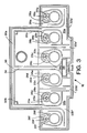
- a battery generally designated 10
- the battery 10 includes three major subassemblies: a battery housing 12, an intermediate cover 14, and an outer cover 16.
- the intermediate cover 14 is normally heat sealed or glued to housing 12 and the outer cover 16 is normally heat sealed to the intermediate cover 14.
- the battery housing 12 typically includes a plurality of partitioned cells 18A-F which are substantially isolated from each other when the covers 14, 16 are sealed onto the housing 12. Since the embodiments of the invention are directed towards providing a leak resistant battery cover, it is understood that various types of venting devices may be incorporated in the leak resistant arrangement and thus particular venting arrangements are not described in detail.
- the intermediate cover 14 and outer cover 16 are designed to form an enclosed labyrinth of passages 20 when the covers 14, 16 are joined.
- FIG 2 a top view of the intermediate cover 14 is shown.
- a cell vent 22 and cell drain 24 (shown in Figure 3) are provided for each battery cell 18.
- the drain 24 is an aperture in the intermediate cover 14 and the vent 22 is formed by a slotted tube 23A-F extending downward from the outer cover 16 into and partially through the aperture forming the drain.
- This drain/vent technique is conventional in the art.
- the cell vent 22 allows for the escape of electrolyte from each cell 18 of the battery 10. In normal operation, the electrolyte gas will condense back into liquid form and drain back into the cell 18 through the cell drain 24.
- the first common passages 30A', 30B' form a portion of the path to atmosphere for three cells 18A-C, 18D-F, respectively.
- the two first common passages 30A', 30B' ultimately combine to form a final common passage 34 at a final convergence point 36.
- the path to atmosphere for each cell 18 is provided by the final common passage 34.
- the final common passage 34 leads to atmosphere via an atmospheric vent 38 placed near the end of the final common passage 34.
- the atmospheric vent 38 is a porous disk located on the outer cover 16.
- the labyrinth of passages 20 is designed to form a very convoluted path to atmosphere.
- the initial passages 26A-F substantially encircle their respective cell vents 22A-F, service ports 40A-F, and typically includes a portion substantially near and along the perimeter portion of the battery prior to reaching the first convergent point 32.
- the perimeter portion of the electrolyte path may also be provided in the first common passage 30 after the first convergent point 32. It is important for the labyrinth of passages 20 to form very convoluted paths prior to reaching the atmospheric vent 38.
- FIG 4 shows a second embodiment of the battery cover constructed according to the present invention.
- electrolyte gases escape through cell vents 122, communicate into an initial passage 126 of the labyrinth 120 through a passage entrance 128 and converges into a first common passage 130A, 130B at a first convergent point 132A, 132B.
- the three initial passages 126A-C, 126D-F for each side of the battery converge into the common passages 130A, 130B, at convergence points 132A, 132B, respectively.
- the common passage 130A ultimately combines with a similar common passage 130B from the other half of the battery to form a final common passage 134 at a final convergent point 136.
- Figure 13 shows yet a further cover embodiment.
- the third embodiment allows electrolyte gas to escape through a cell vent 222 into an initial passage 226 through a passage entrance 228.
- the initial passages 226A, 226B and 226C converge into a first common passage at substantially the same point 232A, 232B.
- the first common passage 230A representing the flow path for one-half of the battery, converges with the first common passage 230B, representing the other half, into a final common passage 234 at final convergent point 236.
- the third embodiment differs from the earlier embodiments in that the final common passage 234 ultimately splits into diverging passages 237A, 237B.
- Each diverging passage 237 communicates with atmospheric vents 238A, 238B, respectively. This arrangement is preferred in dual atmospheric vent embodiments.
- the horizontal and vertical partitions are selectively optional in any of the embodiments.
- a plurality of perpendicular horizontally extending partitions 142 and angled horizontally extending partitions 144 located along the various passages 126, 130 and 134.
- the partitions 142, 144 provide a substantially obstructed path for electrolyte gas or liquid along the passages 126, 130 and 134.
- the angled horizontally extending partitions 144 are preferably angled against the direction of electrolyte flow towards the atmospheric vent 138.
- the horizontally extending partitions 142, 144 extend from the side of the passages 126, 130, 134 towards the center thereof.
- these partitions 142, 144 are arranged to alternate along the passages 126, 130, 134 to provide more effective path obstruction without blocking the path entirely.
- the horizontally extending partitions 142, 144 are positioned in a manner ensuring that electrolyte condensate will not lodge between the partitions 142, 144 or anywhere along the electrolyte path to effectively block the electrolyte path while in normal operation.
- the electrolyte path may also include a plurality of upper vertically extending partitions 150 (shown only in Figure 5) and lower vertically extending partitions 146 (shown only in Figure 4) extending from an upper and lower portion of a passage, respectively.
- the upper vertically extending partitions 150 extend downwardly from the upper portion of the passage 134 while the lower vertically extending partitions 146 extend upwardly from the passage 134.
- the vertically extending partitions 146, 150 are located along the final common passage 134 prior to reaching the atmospheric vent 138.
- a lower vertically extending entrance partition 152 may be placed at the final convergence point 136.
- the vertically extending partitions 146, 150, 152 extend across the width of the entire passage 134.
- the vertically extending entrance partitions 152 (shown only in Figure 4) and the lower vertically extending partitions 146 extend from the intermediate cover 114.
- the upper vertically extending partitions 150 extend from the outer cover 116 and between the lower vertically extending partitions 146 on the intermediate cover 114.
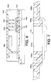
- Figure 6 depicts a cross-sectional view along the final common passage 134 formed by joining the intermediate cover 114 with the outer cover 116.
- the upper and lower vertically extending partitions 146, 150 are alternatingly positioned. a series of "up-and-overs" are formed along the electrolyte path.
- the lower vertically extending partitions 146 and upper vertically extending partitions 150 extend past the ends of the respective partitions 146, 150.
- the upper vertically extending partitions 150 extending from the outer cover 116 are substantially longer than the lower vertically extending partitions 146 extending from the intermediate cover 114. Having the vertically extending partitions 146, 150 configured in this manner provides greater electrolyte leakage protection while inverted. Inverted leak protection is discussed in further detail below.
- the final common passage 134 extends along a transverse axis 154 bisecting the length of the battery.
- the upper portion of the intermediate cover 114 is configured to substantially mirror the lower portion of the outer cover 116 to form the labyrinth of passages 120 and the plurality of various partitions placed throughout. Once the covers 114, 116 are sealed, the passages 126, 130, 134 seal and form enclosed paths.
- the passages 126, 130, 134 which make up the path from the passage entrance 128 to the atmospheric vent 138 are configured to continuously slope from the atmospheric vent 138 to the respective drain hole 124A-F of each cell 18A-F. This sloping configuration returns the electrolyte condensate back to the cells 18A-F after the electrolyte gas has condensed back into a liquid during normal operation.
- the angled horizontally extending partitions 144 are oriented in a manner preventing entrapment of electrolyte condensate during its return to a cell 18A-F.
- Figure 7 is a cross-sectional view of the initial passage 126A and depicts the continuously sloped elevation of the initial passage 126A as it substantially circles and re-circles the cell vent 122 and service port 140.
- the labyrinth of passages 120 is configured to provide a path from each cell vent 122A-F and drain hole 124A-F to the atmospheric vent 138.
- Each path is configured to have a portion above the electrolyte level 162 when the battery is tipped to any one of its sides 164, 166, 168 and 170 or up to ninety (90) degrees from an upright position.
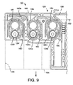
- FIG. 9 a partial cross-sectional view of the labyrinth of passages 120 is shown when the battery is tipped onto side 164.
- the effective electrolyte level in the cells 18A-F is shown at line 162.
- electrolyte 160 will spill into the initial passage 126A-F and any other passages, such as the first common passage 130A, 130B, until an airlock is formed by the electrolyte 160 blocking airflow from the atmospheric vent to the cell 18 and/or when the electrolyte 160 spilling into the labyrinth of passages 120 reaches a level equal to the electrolyte level 162 in the cells 18A-F.
- the electrolyte 160 remains in the initial passage 126A-F because the electrolyte level in the cells 18A-F is below portions of the path formed by the initial passage 126A-F.
- Figure 10 depicts the battery 10 tipped onto side 66.
- the initial passage 126A-F provides a path above the electrolyte level 162 in each cell 18A-F.
- the amount of electrolyte 160 spilling into the labyrinth of passages 120 is stopped once a level equal to the level of electrolyte in the cells 18A-F is reached.
- FIG 11 depicts the battery 10 tipped onto side 168.
- the electrolyte level in each cell 18A-F is higher than the level at which most of the labyrinth of passages 120 is located.
- a path above the electrolyte level 162 is provided for each cell.
- the electrolyte 160 will never reach a level higher than the electrolyte level 162 in the cells 18A-F.
- an airlock will be formed prior to the electrolyte 160 reaching the level shown in Figure 11 because of the very convoluted paths formed by the passages 126, 130, 134.
- These paths provide a substantial hurdle for the electrolyte 160 to overcome in order to reach the atmospheric vent 138.
- Substantial leak protection is accomplished even during agitation. Given the lack of containment chambers and the use of convoluted, narrow paths, applicants' invention provides significant leak protection over existing battery covers.
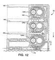
- Figure 12 depicts the battery 10 tipped onto side 170.
- the amount of electrolyte 160 spilled into the cover system is substantially limited to the initial passage 126A-F.
- a path above the cell electrolyte level 162 traps the electrolyte 160.
- the battery 10 would have to undergo substantial rotation and agitation.
- the amount of protection provided by the applicants' invention far exceeds those of the prior art in an economical fashion.
- the battery cover also provides substantial leak resistance in an inverted position as well.
- the battery covers 114, 116 include the upper and lower vertically extending partitions 146, 150, the covers 114, 116 are virtually leak proof.
- the alternating vertically extending partitions 146, 150 help develop an airlock between the cell 18A-F and atmospheric vent 138. The effect is further enhanced if the upper vertically extending partitions 150 on the outer cover 116 are increased in length.
- the lower vertically extending partitions 150 will extend into the path by more than 50% of the path height.
- the vertically extending partitions 150 extend into the path by more than 75% of the path height. The amount of extension for both the lower and upper vertically extending partitions 146, 150 and the spacing between these partitions 146, 150 are such that liquid electrolyte will not form an airlock when the battery is operating in an upright position.
- the covers 114 and 116 provide substantial leak resistance in an inverted position without using the lower and upper vertically extending partitions 146, 150.
- the intricate, convoluted paths formed by the labyrinth of passages 120 in conjunction with the numerous alternating perpendicular and angled horizontally extending partitions 142, 144 will provide a substantial airlock in the paths between the cells 18A-F and the atmospheric vent 138.
- ambient air entering the labyrinth of passages 120 will have substantial difficulty in reaching the cells 18A-F through the various convoluted paths associated therewith. Electrolyte will not enter the labyrinth of passages 120 from the cells 18A-F without air being transferred into the cells 18A-F. Thus, providing an extremely difficult path for air to travel through the electrolyte to the cells 18A-F will substantially reduce electrolyte flow from cells 18A-F.
Landscapes
- Chemical & Material Sciences (AREA)
- Chemical Kinetics & Catalysis (AREA)
- Electrochemistry (AREA)
- General Chemical & Material Sciences (AREA)
- Gas Exhaust Devices For Batteries (AREA)
- Sealing Battery Cases Or Jackets (AREA)
Claims (5)
- Couvercle de batterie anti-fuite pour une batterie au plomb et à l'acide du type comprenant un boítier (12) ayant une pluralité de cellules (18) contenant un électrolyte et une pluralité de parois de séparation séparant lesdites cellules, ledit couvercle comprenant :caractérisé en ce que :un plancher (14) et un plafond (16) formant entre eux un espace intérieur, ledit plancher s'engageant de façon étanche sur le boítier (12) et les parois de séparation ;une pluralité d'évents de cellule qui sont prévus dans et traversent ledit plancher, chaque évent de cellule étant adapté pour mettre en communication avec l'espace intérieur dudit couvercle les gaz à l'intérieur d'une cellule correspondante parmi les cellules de la batterie ;un évent atmosphérique (38) sur ledit couvercle, adapté pour mettre en communication avec l'atmosphère les gaz provenant dudit espace intérieur dudit couvercle ;un système de labyrinthe (20) entre ledit plancher et ledit plafond dans ledit espace intérieur dudit couvercle, formé d'une pluralité de passages, lesdits passages formant une pluralité de chemins sensiblement enroulés pour mettre en communication chacun desdits évents de cellule audit évent atmosphérique, dans lequel chacun desdits évents de cellule communique de façon substantiellement immédiate avec un desdits passages dudit système de labyrinthe ; etune pluralité de canaux d'écoulement prévus dans et traversant ledit plancher, qui communiquent avec lesdits passages et mettent en communication avec les cellules respectives l'électrolyte liquide dans lesdits passages ;lesdits passages dudit système de labyrinthe étant disposés de façon que chacun desdits chemins comprend une branche qui, lors de l'utilisation du couvercle, est au-dessus du niveau d'électrolyte liquide pour la cellule correspondante lorsque la batterie est pivotée d'une valeur allant jusqu'à 90° à l'écart d'une position verticale ;chaque évent de cellule est un évent de cellule en fente (22) s'étendant à partir dudit plafond (16) à travers un canal d'écoulement de cellule (24) correspondant dans ledit plancher (14), chaque évent de cellule ayant une ouverture qui met en communication les gaz provenant de l'intérieur d'une cellule correspondante parmi les cellules de la batterie avec l'espace intérieur dudit couvercle ;le système de labyrinthe comprend des parois qui entourent sensiblement et sont immédiatement adjacentes avec chaque évent de cellule (22) respectif, et qui forment autour de chaque ouverture d'évent un passage initial (26) dans lequel peut être recueilli l'électrolyte qui s'échappe dudit évent de cellule lorsque la batterie n'est pas en position verticale, chacun desdits passages initiaux entourant sensiblement une ouverture d'évent correspondante et communiquant avec au moins un premier passage commun (30), ledit au moins un premier passage commun communiquant avec un passage commun final (34) de telle sorte que ledit passage commun final est en communication avec chacune desdites pluralités de cellules (18) ; etledit évent atmosphérique unique (38) est en communication avec ledit passage commun final (34).
- Couvercle selon la revendication 1, dans lequel l'un au moins desdits passages communs (30, 34) comprend une pluralité de partitions (142) s'étendant généralement horizontalement et pénétrant dans ledit passage pour réaliser, en utilisation, une résistance à tout écoulement de l'électrolyte liquide vers ledit évent atmosphérique.
- Couvercle selon la revendication 1 ou 2, dans lequel l'un au moins desdits passages communs (30, 34) comprend une pluralité de partitions angulées (144) s'étendant généralement horizontalement et pénétrant dans ledit passage pour réaliser, en utilisation, une résistance à tout écoulement de l'électrolyte liquide vers ledit évent atmosphérique.
- Couvercle selon la revendication 1, 2 ou 3, dans lequel l'un au moins desdits passages communs (30, 34) comprend une pluralité de partitions supérieures (150) s'étendant généralement verticalement et une pluralité de partitions inférieures (146) s'étendant généralement verticalement et se développant à partir respectivement des portions supérieure et inférieure dudit passage, lesdites partitions formant un chemin enroulé dirigé vers le haut et vers le bas.
- Couvercle selon l'une quelconque des revendications précédentes, dans lequel lesdits passages initiaux (26) et passages communs (30, 34) sont en pente vers le bas à partir dudit évent atmosphérique (138) en allant vers lesdits canaux d'écoulement de cellule (124).
Applications Claiming Priority (2)
| Application Number | Priority Date | Filing Date | Title |
|---|---|---|---|
| US796423 | 1997-02-06 | ||
| US08/796,423 US5683830A (en) | 1997-02-06 | 1997-02-06 | Leak resistant battery cover |
Publications (2)
| Publication Number | Publication Date |
|---|---|
| EP0858116A1 EP0858116A1 (fr) | 1998-08-12 |
| EP0858116B1 true EP0858116B1 (fr) | 2001-05-23 |
Family
ID=25168166
Family Applications (1)
| Application Number | Title | Priority Date | Filing Date |
|---|---|---|---|
| EP98300835A Expired - Lifetime EP0858116B1 (fr) | 1997-02-06 | 1998-02-05 | Couvercle de batterie anti-fuite |
Country Status (4)
| Country | Link |
|---|---|
| US (3) | US5683830A (fr) |
| EP (1) | EP0858116B1 (fr) |
| AT (1) | ATE201533T1 (fr) |
| DE (1) | DE69800813T2 (fr) |
Cited By (5)
| Publication number | Priority date | Publication date | Assignee | Title |
|---|---|---|---|---|
| AT410493B (de) * | 2001-07-19 | 2003-05-26 | Banner Gmbh | Verschlussvorrichtung |
| EP1962355A1 (fr) | 2007-11-22 | 2008-08-27 | Sociedad Española Del Acumulador Tudor, S.A. | Système de condensation électrolyte pour batteries d'acide de plomb |
| DE10257917B4 (de) * | 2001-12-17 | 2012-10-25 | Akkumulatorenfabrik Moll Gmbh & Co. Kg | Akkumulator |
| WO2024081416A1 (fr) * | 2022-10-14 | 2024-04-18 | Beta Air, Llc | Appareil de ventilation et dimensionnement d'entrefer pour éjectas de batterie de bloc-batterie |
| US11967693B1 (en) | 2022-10-15 | 2024-04-23 | Beta Air, Llc | Battery pack with airgap sizing for preventing ejecta debris clogging |
Families Citing this family (34)
| Publication number | Priority date | Publication date | Assignee | Title |
|---|---|---|---|---|
| US5683830A (en) * | 1997-02-06 | 1997-11-04 | Douglas Battery Manufacturing Company | Leak resistant battery cover |
| US6045940A (en) * | 1998-06-23 | 2000-04-04 | Exide Corporation | Flooded lead acid battery with tilt-over capability |
| US5985482A (en) | 1998-04-28 | 1999-11-16 | Gnb Technologies, Inc. | Snap-on battery heat shield |
| DE19953417A1 (de) * | 1999-11-06 | 2001-05-10 | Vb Autobatterie Gmbh | Mehrzelliger, dicht verschlossener Bleiakkumulator |
| JP3856287B2 (ja) * | 2001-07-02 | 2006-12-13 | エキサイド インダストリーズ リミテッド | 電解液漏れ遅延自動車用バッテリ |
| JP4138275B2 (ja) * | 2001-07-23 | 2008-08-27 | エキサイド インダストリーズ リミテッド | 電解液漏れ抵抗自動車用バッテリ |
| JP4138284B2 (ja) * | 2001-09-25 | 2008-08-27 | エキサイド インダストリーズ リミテッド | 排気型電解液漏れ抵抗二輪自動車用バッテリ |
| DE10254950B4 (de) * | 2002-11-26 | 2005-02-17 | Vb Autobatterie Gmbh | Akkumulator, insbesondere Bleiakkumulator |
| US20060166081A1 (en) * | 2003-01-06 | 2006-07-27 | Tulip Corporation | Battery manifold vent |
| ITVI20040092A1 (it) * | 2004-04-21 | 2004-07-21 | Biasin Srl | Coperchio per contenitori di accumulatori |
| US20050244708A1 (en) * | 2004-05-03 | 2005-11-03 | Doyle Michael A | Battery cover for retention of dielectric fluid |
| US8999565B2 (en) * | 2004-05-03 | 2015-04-07 | Doyle Manufacturing, Inc. | Battery cover for retention of dielectric fluid |
| WO2006129340A1 (fr) * | 2005-05-30 | 2006-12-07 | Gs Yuasa Corporation | Batterie au plomb |
| US7964300B2 (en) * | 2005-09-30 | 2011-06-21 | Tdk-Lambda Corporation | Battery pack |
| KR100844601B1 (ko) * | 2006-11-07 | 2008-07-07 | 세방전지주식회사 | 배터리 케이스 커버 |
| EP2273586B1 (fr) | 2008-04-25 | 2019-07-31 | GS Yuasa International Ltd. | Batterie rechargeable |
| AU2009278426B8 (en) * | 2008-08-08 | 2014-03-06 | Gs Yuasa International Ltd. | Lead-Acid battery |
| JP5331450B2 (ja) * | 2008-11-07 | 2013-10-30 | 株式会社日立製作所 | 蓄電モジュール、蓄電装置、電動機駆動システムおよび車両 |
| KR101815666B1 (ko) * | 2009-01-13 | 2018-01-05 | 존슨 컨트롤스 테크놀러지 컴퍼니 | 누출 방지 배터리 덮개 및 배출구 덮개 |
| DK2597699T3 (en) | 2011-11-25 | 2016-02-15 | Ind Composizione Stampati S R L | Double lid for storage batteries |
| CN202948989U (zh) * | 2012-08-14 | 2013-05-22 | 骆驼集团华中蓄电池有限公司 | 一种具有大回流空间排气结构的铅酸蓄电池盖 |
| CN202948985U (zh) * | 2012-08-14 | 2013-05-22 | 骆驼集团华中蓄电池有限公司 | 一种具有紧凑双孔排气结构的铅酸蓄电池盖 |
| ITVI20120238A1 (it) * | 2012-09-26 | 2014-03-27 | Biasin S R L | Coperchio per accumulatore elettrico |
| KR101285055B1 (ko) * | 2012-11-29 | 2013-07-10 | 세방전지(주) | 축전지의 내누액 방지 커버 |
| US9614210B2 (en) | 2014-09-30 | 2017-04-04 | Johnson Controls Technology Company | Battery module vent system and method |
| US10193115B2 (en) * | 2016-03-23 | 2019-01-29 | East Penn Manufacturing Co. | Battery cover |
| US10601010B2 (en) | 2016-10-26 | 2020-03-24 | Michael A. Doyle | Recombination vent cap |
| US20190173074A1 (en) * | 2017-12-04 | 2019-06-06 | Kabushiki Kaisha Toshiba | Battery |
| JP6973039B2 (ja) * | 2017-12-25 | 2021-11-24 | 株式会社Gsユアサ | 鉛蓄電池 |
| WO2020021909A1 (fr) * | 2018-07-27 | 2020-01-30 | 株式会社Gsユアサ | Batterie au plomb |
| JP7107063B2 (ja) * | 2018-07-27 | 2022-07-27 | 株式会社Gsユアサ | 鉛蓄電池 |
| KR102295775B1 (ko) * | 2019-07-30 | 2021-08-31 | 한국앤컴퍼니 주식회사 | 미로 누액이동경로를 제공하는 납축전지의 누액방지 구조 |
| US11848462B2 (en) * | 2021-02-26 | 2023-12-19 | GM Global Technology Operations LLC | Battery outgassing filter system and method to filter outgassing from a battery cell |
| US11489229B1 (en) * | 2021-12-28 | 2022-11-01 | Beta Air, Llc | System for electric aircraft battery venting using a vent conduit |
Family Cites Families (25)
| Publication number | Priority date | Publication date | Assignee | Title |
|---|---|---|---|---|
| GB233528A (en) * | 1924-05-22 | 1925-05-14 | William Rowland Edwards | Improvements in or relating to boxes or containers for electrical accumulators |
| US2505207A (en) * | 1945-11-14 | 1950-04-25 | Electric Storage Battery Co | Nonspill storage battery |
| US3597280A (en) * | 1968-08-29 | 1971-08-03 | Globe Union Inc | Multiple vent plug assembly |
| US3879227A (en) * | 1973-04-26 | 1975-04-22 | Globe Union Inc | Battery vent plug |
| JPS5748289Y2 (fr) * | 1978-03-04 | 1982-10-22 | ||
| US4207387A (en) * | 1978-08-21 | 1980-06-10 | The Richardson Company | Container for a remotely-vented battery |
| JPS606071B2 (ja) * | 1979-01-20 | 1985-02-15 | 古河電池株式会社 | モノブロツク蓄電池の蓋装置並に製造法 |
| US4306002A (en) * | 1980-05-02 | 1981-12-15 | General Battery Corp. | Multiple cell vent cap for a storage battery |
| US4371591A (en) * | 1980-05-05 | 1983-02-01 | General Battery Corporation | Manifold vented battery cover |
| US4348466A (en) * | 1981-01-27 | 1982-09-07 | Varta Batteries Limited | Anti-spill device for electrolyte battery |
| CA1192947A (fr) * | 1982-10-28 | 1985-09-03 | General Motors Corporation | Systeme d'event a faible relief pour accumulateurs |
| US4486515A (en) * | 1983-12-30 | 1984-12-04 | Chern Jen Tsair | Storage battery electrolyte leak and over-replenishment preventing device |
| DE8430246U1 (de) * | 1984-10-15 | 1985-01-24 | Accumulatorenwerke Hoppecke Carl Zoellner & Sohn GmbH & Co KG, 5790 Brilon | Bleiakkumulator |
| US4613550A (en) * | 1985-08-30 | 1986-09-23 | Gnb Incorporated | Venting system for electric storage batteries |
| US4851305A (en) * | 1988-02-18 | 1989-07-25 | Gnb Incorporated | Cover assemblies for electric storage batteries and batteries utilizing such cover assemblies |
| US5278003A (en) * | 1990-11-16 | 1994-01-11 | Microbat Ltda. | Cover assembly for maintenance-free lead-acid batteries |
| DE9102838U1 (de) * | 1991-03-09 | 1992-07-16 | Robert Bosch Gmbh, 7000 Stuttgart | Akkumulatoren-Batterie |
| DE4216563A1 (de) * | 1992-05-20 | 1993-11-25 | Vb Autobatterie Gmbh | Akkumulator |
| DE9209987U1 (de) * | 1992-07-24 | 1992-09-17 | Accumulatorenwerke Hoppecke Carl Zoellner & Sohn GmbH & Co KG, 5790 Brilon | Bleiakkumulator |
| US5281492A (en) * | 1993-04-29 | 1994-01-25 | Ztong Yee Industrial Co., Ltd. | Cover device of a storage battery |
| IT1270552B (it) * | 1993-06-09 | 1997-05-06 | Olimpio Stocchiero | Contenitore per accumulatori a carica rapida con canali di distribuzione dell' elettrolita stampati sul coperchio |
| EP0630062A1 (fr) * | 1993-06-11 | 1994-12-21 | Exide Corporation | Dispositif d'évaculation groupée pour les gaz de batteries |
| US5424146A (en) * | 1994-10-11 | 1995-06-13 | Cheng Kwang Storage Battery Co., Ltd. | Storage battery with a battery housing that provides protection against leakage |
| US5691076A (en) * | 1995-09-14 | 1997-11-25 | General Motors Corporation | Leak proof venting system for electric storage battery |
| US5683830A (en) | 1997-02-06 | 1997-11-04 | Douglas Battery Manufacturing Company | Leak resistant battery cover |
-
1997
- 1997-02-06 US US08/796,423 patent/US5683830A/en not_active Expired - Fee Related
- 1997-10-31 US US08/961,701 patent/US5843593A/en not_active Ceased
-
1998
- 1998-02-05 DE DE69800813T patent/DE69800813T2/de not_active Expired - Fee Related
- 1998-02-05 EP EP98300835A patent/EP0858116B1/fr not_active Expired - Lifetime
- 1998-02-05 AT AT98300835T patent/ATE201533T1/de not_active IP Right Cessation
-
2000
- 2000-11-01 US US09/704,266 patent/USRE37901E1/en not_active Expired - Fee Related
Cited By (5)
| Publication number | Priority date | Publication date | Assignee | Title |
|---|---|---|---|---|
| AT410493B (de) * | 2001-07-19 | 2003-05-26 | Banner Gmbh | Verschlussvorrichtung |
| DE10257917B4 (de) * | 2001-12-17 | 2012-10-25 | Akkumulatorenfabrik Moll Gmbh & Co. Kg | Akkumulator |
| EP1962355A1 (fr) | 2007-11-22 | 2008-08-27 | Sociedad Española Del Acumulador Tudor, S.A. | Système de condensation électrolyte pour batteries d'acide de plomb |
| WO2024081416A1 (fr) * | 2022-10-14 | 2024-04-18 | Beta Air, Llc | Appareil de ventilation et dimensionnement d'entrefer pour éjectas de batterie de bloc-batterie |
| US11967693B1 (en) | 2022-10-15 | 2024-04-23 | Beta Air, Llc | Battery pack with airgap sizing for preventing ejecta debris clogging |
Also Published As
| Publication number | Publication date |
|---|---|
| ATE201533T1 (de) | 2001-06-15 |
| DE69800813T2 (de) | 2002-03-28 |
| EP0858116A1 (fr) | 1998-08-12 |
| USRE37901E1 (en) | 2002-11-05 |
| US5843593A (en) | 1998-12-01 |
| DE69800813D1 (de) | 2001-06-28 |
| US5683830A (en) | 1997-11-04 |
Similar Documents
| Publication | Publication Date | Title |
|---|---|---|
| EP0858116B1 (fr) | Couvercle de batterie anti-fuite | |
| EP1280214B1 (fr) | Une batterie anti-fuite d'un véhicule automobile | |
| JP4138284B2 (ja) | 排気型電解液漏れ抵抗二輪自動車用バッテリ | |
| US8304137B2 (en) | Fuel cell housing structure | |
| US5691076A (en) | Leak proof venting system for electric storage battery | |
| US3597280A (en) | Multiple vent plug assembly | |
| US5731100A (en) | Battery cover | |
| JP2005166318A (ja) | 鉛蓄電池 | |
| JP2017091950A (ja) | 車載用バッテリ装置 | |
| EP0627775A1 (fr) | Bouchon de ventilation munis de moyens pour le retour de l'électrolyte et pour attenuer l'explosion | |
| US4778735A (en) | Storage battery gang vent cap | |
| JP7070448B2 (ja) | 排煙ダクト | |
| EP0630062A1 (fr) | Dispositif d'évaculation groupée pour les gaz de batteries | |
| DE59300881D1 (de) | Akkumulator mit im Deckel Befindlichem Entgasungssystem. | |
| JP2005197148A (ja) | 鉛蓄電池用液口栓および鉛蓄電池 | |
| US6660426B2 (en) | Multi-cell storage battery with gas vent in a cover assembly | |
| US4403019A (en) | Venting system for electric storage battery | |
| EP0107469B1 (fr) | Système de ventilation à profil bas pour accumulateur électrique | |
| US6045940A (en) | Flooded lead acid battery with tilt-over capability | |
| JP2009016063A (ja) | 蓄電池 | |
| US6881513B2 (en) | Leak retardant automotive battery | |
| NO306085B1 (no) | Akkumulator, saerlig blyakkumulator, fortrinnsvis for nyttekjöretöy | |
| CA2324232C (fr) | Accumulateur au plomb a pile ouverte capable d'inclinaison | |
| WO2020021909A1 (fr) | Batterie au plomb | |
| SU909729A1 (ru) | Устройство дл доливки воды в аккумул тор |
Legal Events
| Date | Code | Title | Description |
|---|---|---|---|
| PUAI | Public reference made under article 153(3) epc to a published international application that has entered the european phase |
Free format text: ORIGINAL CODE: 0009012 |
|
| AK | Designated contracting states |
Kind code of ref document: A1 Designated state(s): AT DE ES FI FR GB IT PT |
|
| AX | Request for extension of the european patent |
Free format text: AL;LT;LV;MK;RO;SI |
|
| 17P | Request for examination filed |
Effective date: 19990205 |
|
| AKX | Designation fees paid |
Free format text: AT BE CH DE DK ES FI FR LI |
|
| RBV | Designated contracting states (corrected) |
Designated state(s): AT BE CH DE DK ES FI FR LI |
|
| RBV | Designated contracting states (corrected) |
Designated state(s): AT DE ES FI FR GB IT PT |
|
| 17Q | First examination report despatched |
Effective date: 19990329 |
|
| GRAG | Despatch of communication of intention to grant |
Free format text: ORIGINAL CODE: EPIDOS AGRA |
|
| GRAG | Despatch of communication of intention to grant |
Free format text: ORIGINAL CODE: EPIDOS AGRA |
|
| GRAH | Despatch of communication of intention to grant a patent |
Free format text: ORIGINAL CODE: EPIDOS IGRA |
|
| GRAH | Despatch of communication of intention to grant a patent |
Free format text: ORIGINAL CODE: EPIDOS IGRA |
|
| GRAA | (expected) grant |
Free format text: ORIGINAL CODE: 0009210 |
|
| AK | Designated contracting states |
Kind code of ref document: B1 Designated state(s): AT DE ES FI FR GB IT PT |
|
| PG25 | Lapsed in a contracting state [announced via postgrant information from national office to epo] |
Ref country code: IT Free format text: LAPSE BECAUSE OF FAILURE TO SUBMIT A TRANSLATION OF THE DESCRIPTION OR TO PAY THE FEE WITHIN THE PRESCRIBED TIME-LIMIT;WARNING: LAPSES OF ITALIAN PATENTS WITH EFFECTIVE DATE BEFORE 2007 MAY HAVE OCCURRED AT ANY TIME BEFORE 2007. THE CORRECT EFFECTIVE DATE MAY BE DIFFERENT FROM THE ONE RECORDED. Effective date: 20010523 Ref country code: FR Free format text: LAPSE BECAUSE OF FAILURE TO SUBMIT A TRANSLATION OF THE DESCRIPTION OR TO PAY THE FEE WITHIN THE PRESCRIBED TIME-LIMIT Effective date: 20010523 Ref country code: FI Free format text: LAPSE BECAUSE OF FAILURE TO SUBMIT A TRANSLATION OF THE DESCRIPTION OR TO PAY THE FEE WITHIN THE PRESCRIBED TIME-LIMIT Effective date: 20010523 Ref country code: AT Free format text: LAPSE BECAUSE OF FAILURE TO SUBMIT A TRANSLATION OF THE DESCRIPTION OR TO PAY THE FEE WITHIN THE PRESCRIBED TIME-LIMIT Effective date: 20010523 |
|
| REF | Corresponds to: |
Ref document number: 201533 Country of ref document: AT Date of ref document: 20010615 Kind code of ref document: T |
|
| REF | Corresponds to: |
Ref document number: 69800813 Country of ref document: DE Date of ref document: 20010628 |
|
| PG25 | Lapsed in a contracting state [announced via postgrant information from national office to epo] |
Ref country code: PT Free format text: LAPSE BECAUSE OF FAILURE TO SUBMIT A TRANSLATION OF THE DESCRIPTION OR TO PAY THE FEE WITHIN THE PRESCRIBED TIME-LIMIT Effective date: 20010823 |
|
| PG25 | Lapsed in a contracting state [announced via postgrant information from national office to epo] |
Ref country code: ES Free format text: LAPSE BECAUSE OF FAILURE TO SUBMIT A TRANSLATION OF THE DESCRIPTION OR TO PAY THE FEE WITHIN THE PRESCRIBED TIME-LIMIT Effective date: 20011130 |
|
| EN | Fr: translation not filed | ||
| REG | Reference to a national code |
Ref country code: GB Ref legal event code: IF02 |
|
| PLBE | No opposition filed within time limit |
Free format text: ORIGINAL CODE: 0009261 |
|
| STAA | Information on the status of an ep patent application or granted ep patent |
Free format text: STATUS: NO OPPOSITION FILED WITHIN TIME LIMIT |
|
| 26N | No opposition filed | ||
| PGFP | Annual fee paid to national office [announced via postgrant information from national office to epo] |
Ref country code: GB Payment date: 20040204 Year of fee payment: 7 |
|
| PGFP | Annual fee paid to national office [announced via postgrant information from national office to epo] |
Ref country code: DE Payment date: 20040423 Year of fee payment: 7 |
|
| PG25 | Lapsed in a contracting state [announced via postgrant information from national office to epo] |
Ref country code: GB Free format text: LAPSE BECAUSE OF NON-PAYMENT OF DUE FEES Effective date: 20050205 |
|
| PG25 | Lapsed in a contracting state [announced via postgrant information from national office to epo] |
Ref country code: DE Free format text: LAPSE BECAUSE OF NON-PAYMENT OF DUE FEES Effective date: 20050901 |
|
| GBPC | Gb: european patent ceased through non-payment of renewal fee |
Effective date: 20050205 |