EP0858115B1 - Dachelement mit einer Solarzelle und Einbauverfahren - Google Patents
Dachelement mit einer Solarzelle und Einbauverfahren Download PDFInfo
- Publication number
- EP0858115B1 EP0858115B1 EP98101909A EP98101909A EP0858115B1 EP 0858115 B1 EP0858115 B1 EP 0858115B1 EP 98101909 A EP98101909 A EP 98101909A EP 98101909 A EP98101909 A EP 98101909A EP 0858115 B1 EP0858115 B1 EP 0858115B1
- Authority
- EP
- European Patent Office
- Prior art keywords
- roof
- metal
- conductive
- retaining clip
- solar cell
- Prior art date
- Legal status (The legal status is an assumption and is not a legal conclusion. Google has not performed a legal analysis and makes no representation as to the accuracy of the status listed.)
- Expired - Lifetime
Links
Images


Classifications
-
- E—FIXED CONSTRUCTIONS
- E04—BUILDING
- E04D—ROOF COVERINGS; SKY-LIGHTS; GUTTERS; ROOF-WORKING TOOLS
- E04D3/00—Roof covering by making use of flat or curved slabs or stiff sheets
- E04D3/36—Connecting; Fastening
- E04D3/366—Connecting; Fastening by closing the space between the slabs or sheets by gutters, bulges, or bridging elements, e.g. strips
-
- E—FIXED CONSTRUCTIONS
- E04—BUILDING
- E04D—ROOF COVERINGS; SKY-LIGHTS; GUTTERS; ROOF-WORKING TOOLS
- E04D13/00—Special arrangements or devices in connection with roof coverings; Protection against birds; Roof drainage ; Sky-lights
-
- F—MECHANICAL ENGINEERING; LIGHTING; HEATING; WEAPONS; BLASTING
- F24—HEATING; RANGES; VENTILATING
- F24S—SOLAR HEAT COLLECTORS; SOLAR HEAT SYSTEMS
- F24S25/00—Arrangement of stationary mountings or supports for solar heat collector modules
- F24S25/20—Peripheral frames for modules
-
- F—MECHANICAL ENGINEERING; LIGHTING; HEATING; WEAPONS; BLASTING
- F24—HEATING; RANGES; VENTILATING
- F24S—SOLAR HEAT COLLECTORS; SOLAR HEAT SYSTEMS
- F24S25/00—Arrangement of stationary mountings or supports for solar heat collector modules
- F24S25/30—Arrangement of stationary mountings or supports for solar heat collector modules using elongate rigid mounting elements extending substantially along the supporting surface, e.g. for covering buildings with solar heat collectors
- F24S25/33—Arrangement of stationary mountings or supports for solar heat collector modules using elongate rigid mounting elements extending substantially along the supporting surface, e.g. for covering buildings with solar heat collectors forming substantially planar assemblies, e.g. of coplanar or stacked profiles
-
- F—MECHANICAL ENGINEERING; LIGHTING; HEATING; WEAPONS; BLASTING
- F24—HEATING; RANGES; VENTILATING
- F24S—SOLAR HEAT COLLECTORS; SOLAR HEAT SYSTEMS
- F24S25/00—Arrangement of stationary mountings or supports for solar heat collector modules
- F24S25/40—Arrangement of stationary mountings or supports for solar heat collector modules using plate-like mounting elements, e.g. profiled or corrugated plates; Plate-like module frames
-
- F—MECHANICAL ENGINEERING; LIGHTING; HEATING; WEAPONS; BLASTING
- F24—HEATING; RANGES; VENTILATING
- F24S—SOLAR HEAT COLLECTORS; SOLAR HEAT SYSTEMS
- F24S25/00—Arrangement of stationary mountings or supports for solar heat collector modules
- F24S25/60—Fixation means, e.g. fasteners, specially adapted for supporting solar heat collector modules
- F24S25/63—Fixation means, e.g. fasteners, specially adapted for supporting solar heat collector modules for fixing modules or their peripheral frames to supporting elements
- F24S25/632—Side connectors; Base connectors
-
- H—ELECTRICITY
- H02—GENERATION; CONVERSION OR DISTRIBUTION OF ELECTRIC POWER
- H02S—GENERATION OF ELECTRIC POWER BY CONVERSION OF INFRARED RADIATION, VISIBLE LIGHT OR ULTRAVIOLET LIGHT, e.g. USING PHOTOVOLTAIC [PV] MODULES
- H02S20/00—Supporting structures for PV modules
- H02S20/20—Supporting structures directly fixed to an immovable object
- H02S20/22—Supporting structures directly fixed to an immovable object specially adapted for buildings
- H02S20/23—Supporting structures directly fixed to an immovable object specially adapted for buildings specially adapted for roof structures
-
- E—FIXED CONSTRUCTIONS
- E04—BUILDING
- E04D—ROOF COVERINGS; SKY-LIGHTS; GUTTERS; ROOF-WORKING TOOLS
- E04D3/00—Roof covering by making use of flat or curved slabs or stiff sheets
- E04D3/36—Connecting; Fastening
- E04D3/365—Connecting; Fastening by simple overlapping of the marginal portions with use of separate connecting elements, e.g. hooks or bolts for corrugated sheets
-
- F—MECHANICAL ENGINEERING; LIGHTING; HEATING; WEAPONS; BLASTING
- F24—HEATING; RANGES; VENTILATING
- F24S—SOLAR HEAT COLLECTORS; SOLAR HEAT SYSTEMS
- F24S25/00—Arrangement of stationary mountings or supports for solar heat collector modules
- F24S2025/01—Special support components; Methods of use
- F24S2025/022—Sealing means between support elements, e.g. overlapping arrangements; Gap closing arrangements
-
- Y—GENERAL TAGGING OF NEW TECHNOLOGICAL DEVELOPMENTS; GENERAL TAGGING OF CROSS-SECTIONAL TECHNOLOGIES SPANNING OVER SEVERAL SECTIONS OF THE IPC; TECHNICAL SUBJECTS COVERED BY FORMER USPC CROSS-REFERENCE ART COLLECTIONS [XRACs] AND DIGESTS
- Y02—TECHNOLOGIES OR APPLICATIONS FOR MITIGATION OR ADAPTATION AGAINST CLIMATE CHANGE
- Y02B—CLIMATE CHANGE MITIGATION TECHNOLOGIES RELATED TO BUILDINGS, e.g. HOUSING, HOUSE APPLIANCES OR RELATED END-USER APPLICATIONS
- Y02B10/00—Integration of renewable energy sources in buildings
- Y02B10/10—Photovoltaic [PV]
-
- Y—GENERAL TAGGING OF NEW TECHNOLOGICAL DEVELOPMENTS; GENERAL TAGGING OF CROSS-SECTIONAL TECHNOLOGIES SPANNING OVER SEVERAL SECTIONS OF THE IPC; TECHNICAL SUBJECTS COVERED BY FORMER USPC CROSS-REFERENCE ART COLLECTIONS [XRACs] AND DIGESTS
- Y02—TECHNOLOGIES OR APPLICATIONS FOR MITIGATION OR ADAPTATION AGAINST CLIMATE CHANGE
- Y02B—CLIMATE CHANGE MITIGATION TECHNOLOGIES RELATED TO BUILDINGS, e.g. HOUSING, HOUSE APPLIANCES OR RELATED END-USER APPLICATIONS
- Y02B10/00—Integration of renewable energy sources in buildings
- Y02B10/20—Solar thermal
-
- Y—GENERAL TAGGING OF NEW TECHNOLOGICAL DEVELOPMENTS; GENERAL TAGGING OF CROSS-SECTIONAL TECHNOLOGIES SPANNING OVER SEVERAL SECTIONS OF THE IPC; TECHNICAL SUBJECTS COVERED BY FORMER USPC CROSS-REFERENCE ART COLLECTIONS [XRACs] AND DIGESTS
- Y02—TECHNOLOGIES OR APPLICATIONS FOR MITIGATION OR ADAPTATION AGAINST CLIMATE CHANGE
- Y02E—REDUCTION OF GREENHOUSE GAS [GHG] EMISSIONS, RELATED TO ENERGY GENERATION, TRANSMISSION OR DISTRIBUTION
- Y02E10/00—Energy generation through renewable energy sources
- Y02E10/40—Solar thermal energy, e.g. solar towers
- Y02E10/47—Mountings or tracking
-
- Y—GENERAL TAGGING OF NEW TECHNOLOGICAL DEVELOPMENTS; GENERAL TAGGING OF CROSS-SECTIONAL TECHNOLOGIES SPANNING OVER SEVERAL SECTIONS OF THE IPC; TECHNICAL SUBJECTS COVERED BY FORMER USPC CROSS-REFERENCE ART COLLECTIONS [XRACs] AND DIGESTS
- Y02—TECHNOLOGIES OR APPLICATIONS FOR MITIGATION OR ADAPTATION AGAINST CLIMATE CHANGE
- Y02E—REDUCTION OF GREENHOUSE GAS [GHG] EMISSIONS, RELATED TO ENERGY GENERATION, TRANSMISSION OR DISTRIBUTION
- Y02E10/00—Energy generation through renewable energy sources
- Y02E10/50—Photovoltaic [PV] energy
Definitions
- the present invention relates to a roof member incorporating a solar cell. More particularly, the invention concerns a roof member easy to install and excellent in electric safety and an electrically grounding method of a metal reinforcing member of a combination solar cell and roof member.
- the ordinary solar cell modules are constructed in such structure that a photovoltaic element is sealed in a filling material, the surface is covered with a weather-resistant film or glass as a protective material, and a metal reinforcing member is attached to the circumference or the back surface.
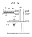
- Figs. 13 and 14 show a conventional frame mount type solar cell device.
- the solar cell module array of this conventional example is constructed of a plurality of solar cell modules 1301 fixed to frame 1302.
- a solar cell module used in this conventional example is constructed in such structure that a solar cell element 1401 is sealed in resin 1404, the top surface is protected by glass 1403, the bottom surface by weather-resistant film 1402, and an aluminum frame 1405 for reinforcement and mounting to the frame is attached to the circumference.
- the present invention provides a specific method for electric grounding of a combination solar cell and roof member (a solar-cell-incorporated roof material) installed on the roof.
- Roof members are those fixed to the roof, each roof member being a combination solar cell and roof member having a solar cell element and a metal reinforcing member, wherein a metal member is provided below the combination solar cell and roof member or a metal member is provided along an adjacent portion between adjacent combination solar cell and roof members, wherein the metal member is made electrically conductive to metal reinforcing members of plural combination solar cell and roof members and wherein the metal member is electrically grounded.
- the metal member is preferably a metal sheet disposed below the combination solar cell and roof member, a metal sheet disposed between adjacent combination solar cell and roof members, or a metal sheet mounted on a wood rafter.
- the metal member is preferably one also serving as a metal rafter, a long retaining clip, or a cover for the adjacent portion of the combination solar cell and roof member.
- electric conduction is preferably achieved between the metal reinforcing member of combination solar cell and roof member and the metal member provided on the roof substrate through a partially conductive retaining clip.
- the retaining clip has a screw and that the electric condition is made surer between the metal reinforcing member of the combination solar cell and roof member and the retaining clip through the screw.
- a combination solar cell and roof member of the present invention incorporates a roof member and a solar cell element to compose a roof member and an example of the shape thereof is shown in Fig. 4.
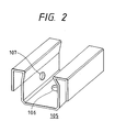
- Fig. 1 is a cross-sectional view to show a mounted state of the roof members shown in Fig. 4.
- Metal rafter 108 is prepared as a metal member located below the combination solar cell and roof members 101 and is fixed on purlins 115 as shown in Fig. 1.
- Heat insulating material 110 is placed and fixed between metal rafters 108.
- Each combination solar cell and roof member 101 is retained by retaining clip 105 to be fixed to the metal rafter 108.
- Screws 113 are attached to the retaining clip 105 so that the tip thereof is urged against the metal reinforcing member of combination solar cell and roof member to achieve electric connection.
- Base metal member 114 and decorative cover 111 are mounted over the fixing portion of the retaining clip. Further, a cable is attached to each metal rafter, thereby achieving electric grounding.
- a substrate roof or the like may be provided underneath the roof members in order to enhance fire protection and waterproofing, thereby forming the structure of double-layered roof.
- the retaining clip 105 has a portion to be fixed to the rafter and portions for retaining the combination solar cell and roof member.
- the retaining clip is fixed to a support member such as the rafter by use of a through hole of 106 in the drawing.
- mating part 107 is a portion to which a screw for assuring electric conduction to the retaining clip is attached.
- the retaining clip is tapped for fixing the screw to the retaining clip; or another means that may be employed is, for example, welding a nut to the retaining clip.
- a tapping screw may be used.
- Another conceivable means for making the electric conduction surer is, for example, a method for forming a through hole in the combination solar cell and roof member, inserting the screw therein, and coupling the screw with a nut while pinching the metal reinforcing member portion of combination solar cell and roof member and the retaining clip.
- Another method contemplated is a method for placing a conductive plate spring member made of a conductive rubber or of a thin metal sheet such as stainless steel between the retaining clip and the metal reinforcing member of combination solar cell and roof member.
- Still another method contemplated is a method for applying tin plating to contact portions between the retaining clip and the metal reinforcing member of combination solar cell and roof member.
- the retaining clip needs to have the electrically conductive property to the metal reinforcing member of combination solar cell and roof member, it is desired to have the electrically conductive property at least in a part thereof. Further, since the retaining clip has the function to install the combination solar cell and roof member on the rafter, it is desired to have strength enough therefor.
- the strength may be further enhanced, for example, by using a long retaining clip for retaining the entire length of one side of the combination solar cell and roof member.
- combination solar cell and roof member may be retained at plural portions or at one portion.
- the electric conduction between the metal reinforcing member of combination solar cell and roof member and the retaining clip needs to be given at at least one portion for each solar cell module, and the other retaining clips for simply retaining the combination solar cell and roof member may be those without account of electric conduction.
- the retaining clip can be made by processing a metal sheet. Specifically, the retaining clip can be prepared, for example, by press working or folding of a stainless steel sheet or a galvanized iron sheet 0.8 mm or 1 mm thick. Further, the retaining clip can also be made of a composite material such as a lamination with a silver sheet or a copper sheet in order to increase the electric conductivity.
- means for electrically grounding the retaining clip include a method for preliminarily attaching a cable for electric grounding to the retaining clip or a method for fixing the retaining clip to a conductive rafter by use of a bolt or the like and the electrically grounding the rafter.
- Examples of the metal member placed on the roof substrate are a metal rafter, a wood rafter with a metal sheet attached thereto, a metal sheet cut in a rectangular shape, and so on.
- a metal rafter a wood rafter with a metal sheet attached thereto, a metal sheet cut in a rectangular shape, and so on.
- One of these is selected considering compatibility with the construction method of the substrate of building.
- the metal rafter functions not only as an electrically conductive material, but also as a structural material.
- the metal rafter may be made of light gage steel, hat steel, lip channel steel, H-steel, or the like obtained by folding of a thin steel sheet.
- the combination of the metal sheet with the ordinary wood rafter is particularly suitable for applications to timber-structure buildings.
- the cross section of this metal sheet is preferably determined as large as possible.
- the metal sheet in order to reduce work amounts on the roof, is preferably preliminarily incorporated with the rafter.
- the method of incorporation may be a method for bending the metal sheet in a U-shape to cover the rafter, or a method for fixing the rafter and the metal sheet having the equal or near width by screwing. This permits employment of a fixing method such as nailing, taking advantage of the properties of wood, and can decrease the weight.
- the metal sheet may be a galvanized iron sheet, a stainless steel sheet, or the like.
- the same effect can be achieved as to the electric grounding of the metal reinforcing member of combination solar cell and roof member by preparing the metal sheet having a small width and a length ranging from the edge to the edge of roof below the roof member. If this metal sheet is installed in a network pattern, the electric grounding can be done readily for the all combination solar cell and roof members on the roof.
- the electric grounding can be achieved, for example, by a method for attaching a cable to each metal rafter and guiding the cables into the interior in the same manner as the output cables of solar batteries to electrically ground them.
- a means for achieving electric conduction between the metal rafters may be adopted in order to realize the electric grounding by such attachment of cable at only one portion.
- the electric grounding between the rafters can be achieved by electric conduction between the metal rafters and the metal purlins with the bolts and by electric grounding of the purlins.
- the electric conduction may be attained between the rafters by use of an eave edge plate, a verge plate, a ridge cover, a dummy plate, or the like attached to the circumference of the roof.
- the rafters may be provided with through holes or grooves through which the output cables between the combination solar cell and roof members pass, if necessary.
- the metal member placed along the adjacent portion of the combination solar cell and roof member can be a metal sheet installed by a method for fixing the metal sheet, utilizing the space of the adjacent portion.
- the metal sheet of the U-shape may be preliminarily incorporated with the batten.
- It may also be a long retaining clip also functioning to fix the combination solar cell and roof member or may also function as a decorative cover of the adjacent portion.
- Its length is preferably enough to stretch from the edge to the edge of the roof.
- the electric conduction with the combination solar cell and roof members and electric grounding are the same as in the case of the metal member mounted on the roof substrate and located below the combination solar cell and roof member.
- FIG. 10 A schematic, cross-sectional, structural view of the combination solar cell and roof member is next shown in Fig. 10.
- reference numeral 1001 designates a photovoltaic element, 1002 a bottom-surface reinforcing metal sheet, 1003 a weather-resistant film, and 1004 a filling material.
- the metal reinforcing member is preferably used in order to assure the strength of the roof.
- the metal reinforcing member may be a metal frame member of aluminum or stainless steel in a nearly U-shape, attached to a part or the circumference, but a more preferred member is a metal sheet or a metal reinforcing member formed of the metal sheet in a box shape or in various roof shapes.
- Desired conditions of the metal sheet are having sufficient strength as a structure, being bendable and excellent in processability, having high weather resistance and corrosion resistance, having high adhesive strength to an adhesive for bonding the solar cell element, and so on.
- Another desired condition is that color tones are selectable, because the tone will affect the external view, depending upon the installation form.
- the metal reinforcing member is selected from steel sheets, special plated steel sheets, laminate/coated steel sheets, or the like, specifically, such as a copper plate, an aluminum alloy sheet, a lead sheet, a zinc sheet, a titanium sheet, a stainless steel sheet, a galvanized steel sheet, or a zinc-aluminum alloy plated steel sheet.
- the thickness of these is preferably 0.2 mm-2.0 mm. It is preferably colored with a polyester-resin-based paint, an epoxy-resin-based paint or the like, but, for achieving surer electric conduction to the retaining clip, the coating film may be taken away in a portion for electric conduction to the retaining clip. Further, it is also permissible to use a metal sheet or the like coated only in a portion that could affect the external view of the roof after mounted.
- This surface protective material is preferably excellent in transparency and weather resistance and it preferably has volatility in order to prevent pollution of the surface.
- the surface protective material is a glass film or a weather-resistant film.
- a particularly preferred material is the weather-resistant film that can readily address the weight reduction and the scale increase of combination solar cell and roof member.
- the solar cell element is preferably sealed in the filling material in order to protect the solar cell element from the external environments such as the impact.
- the filling material are ethylene-vinyl acetate copolymer (EVA), ethylene-acrylate copolymer resin (EEA), polyvinylbutyral (PVB), silicone resin, and acrylic resin.
- Thin-film semiconductor solar cells of the non-monocrystalline type are particularly suitable as solar cell elements used in the roof members of the present invention.
- An example of the solar cell element is shown in Fig. 9.
- numeral 901 denotes a substrate, 902 a bottom reflecting layer, 903 a semiconductor photoactive layer, 904 a transparent, conductive layer, and 905 a collector electrode.
- the solar cell element may be of the structure in which light is incident from the substrate side.
- a material for the semiconductor photoactive layer can be selected from silicon-based materials and compound-based materials, and the semiconductor junction can be selected from the pn junction, the pin junction, and the Schottky junction.
- the roof members shown in Fig. 4 were produced and mounted so as to achieve good grounding.
- amorphous silicon solar cell element 1001 was sandwiched between sheets of EVA (a weather-resistant grade of ethylene-vinyl acetate copolymer; trade name: Evaflex 150, available from Mitsui-DuPont Chemical Inc.) on a galvanized steel sheet coated with a polyester resin (trade name: Color Grip, available from Daido Kohan Kabushiki Kaisha) 1002 having the thickness of 0.4 mm, and then ETFE (ethylene-tetrafluoroethylene; trade name: Aflex, available from Asahi Glass) 1004 was placed thereon. These were pressed in vacuum and heated to form an integral body incorporating the steel sheet and solar cell element. Then junction boxes and cables with a connector for leading the power from the solar cell element to the outside were attached to the back side.
- Fig. 3 shows a method for mounting the combination solar cell and roof members of the present example on the roof.
- a plurality of metal rafters 108 were placed in parallel on metal purlins and were fixed with drill screws.
- An excelsior board was placed and fixed as a heat insulating member 110 between the metal rafters 108 on the purlins.
- the metal rafters 108 were provided with through holes 109 for connection between combination solar cell and roof members 101, and spaces for cable 103 to pass were given in the heat insulating member 110.
- the combination solar cell and roof members 101 were placed on the rafters 108 and electric connection was made by connecting the connectors 104 between the combination solar cell and roof members 101.
- the combination solar cell and roof members 101 were retained by retaining clips 105 shown in Fig. 2 and were fixed to the rafters 108 with drill screws 112. Further, the combination solar cell and roof members 101 were urged and fixed at the mating portions 113 of retaining clips 105 by screws.
- base metal members 114 were fitted and fixed and then decorative covers 111 were attached over them as seen in the cross-sectional view of Fig. 1.
- a polyvinyl chloride wire of 5.5 mm 2 was attached by a stainless-steel bolt to the vicinity of the ridge-side edge of the center metal rafter, the wire was then led from the ridge side of the roof into the interior in the same manner as the output cables from the solar cells, and it was electrically grounded.
- each combination solar cell and roof member in the present example will be described referring to Fig. 1.
- electric conduction is achieved from the metal reinforcing member of the combination solar cell and roof member 101 via the screw 113, the retaining clip 105, and the tapping bolt 112 for fixing the retaining clip, to the metal rafter 108. Since the metal rafters 108 extend from the edge of the ridge to the edge of the eave, the metal reinforcing members of the all combination solar cell and roof members 101 arranged in the eave-ridge direction can be made electrically conductive to one metal rafter 108.
- Each metal rafter 108 is electrically conductive to the metal purlins 115 via the tapping screws 116. Since the metal purlins 115 extend from the left and right edges of the roof, the all metal purlins arranged horizontally in parallel can also be made electrically conductive similarly. As a result, the metal reinforcing members of the all combination solar cell and roof members 101 are made electrically conductive to one metal rafter 108 and, finally, are electrically grounded through a wire attached to that metal rafter.
- the combination solar cell and roof members were installed without any frame on the laid roof, whereby the cost was able to be decreased greatly and the preferred exterior view was achieved with excellent unification of the roof and building.
- the combination solar cell and roof member had the metal sheet on the bottom surface, had the form similar to that of the conventional metal roof, and was fixed by the retaining clips, installation was able to be done with high reliability and work efficiency.
- the combination solar cell and roof member of the present example is constructed substantially in the same structure as in Example 1 except that the roof member is of the configuration of installation of a horizontal roofing type roof.
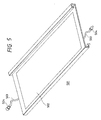
- the integral combination of the metal reinforcing member and the solar cell element as shown in Fig. 10 was bent in the shape shown in Fig. 5.
- the edge located on the eave side when mounted on the roof was bent toward the bottom side of the combination solar cell and roof member 501 to form an eave-side engaging portion of a U-shape and the edge located on the ridge side was bent upward and then folded back to form a ridge-side engaging portion.
- junction boxes and cables 503 with a connector 504 for electric connection between solar cells were attached in the same manner as in Example 1.
- the excelsior board as heat insulating member 510 was placed and fixed between the rafters.
- the combination solar cell and roof members 501 were fixed on the roof in the following manner. Fixing of the solar cell modules was first started from the eave side; the combination solar cell and roof members in a horizontal line were fixed on the eave side and thereafter the fixing was successively conducted line by line of combination solar cell and roof members toward the ridge side.
- Electric connection between combination solar cell and roof members 501 was achieved by successively connecting the cables 503 with connector 504 while fixing the combination solar cell and roof members.
- the most-eave-side combination solar cell and roof members 501 were made to engage eave arabesque 509 and the roof members thereafter were made to engage those 501 next thereto on the eave side from thereabove.
- the ridge-side engaging portions standing on the ridge side were retained by retaining clips 505 from thereabove and the base of each retaining clip 505 was fixed to the metal rafter 508 with tapping screw 514.
- a retaining clip 505 has a through hole 506 through which a tapping screw 514 for fixing the retaining clip to the metal rafter 508 and a mating portion 507 to which a screw for making the electric conduction to the module surer is attached, as shown in Fig. 6.
- conductive screw 515 was tightened so as to be urged against the combination solar cell and roof member, after the fixation of the retaining clip 505. This tightening of the screw 515 made electric conduction surer between the combination solar cell and roof member 501 and the retaining clip 505.
- a cable was attached to the ridge-side end of the metal rafter 508 and was guided through a hole on a sheathing roof board into the interior in the same manner as the output cables of solar cells.
- each combination solar cell and roof member in the present example will be described.
- electric conduction is achieved from the metal reinforcing member of the combination solar cell and roof member via the screw, the retaining clip, and the tapping bolt for fixing the retaining clip, to the metal rafter. Since the metal rafters extend from the edge of the ridge to the edge of the eave, the metal reinforcing members of the all combination solar cell and roof members arranged in the eave-ridge direction can be made electrically conductive to one metal rafter. Each metal rafter is electrically conductive to the metal purlins via the tapping screws.
- the all metal purlins extend from the left and right edges of the roof, the all metal purlins arranged horizontally in parallel can also be made electrically conductive similarly.
- the metal reinforcing members of the all combination solar cell and roof members are made electrically conductive to one metal rafter and, finally, are electrically grounded through the wire attached to that metal rafter.
- the roof members of the present example realized the mounting of combination solar cell and roof members and the electric grounding of the metal outside portions of combination solar cell and roof members with high work efficiency and at low cost, in the same manner as in Example 1, and the roof members had the excellent external view of the horizontal roofing type roof having the nearly stepped external view and being employed preferentially in the conventional buildings.
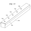
- the combination solar cell and roof member array of the present example is substantially the same as in Example 1 except that wood rafters are covered by a stainless steel sheet to achieve electric conduction between the metal reinforcing members of combination solar cell and roof members.
- a rafter 1101 is covered with a stainless steel sheet as a conductive portion 1102, which is a means for achieving conduction to retaining clips.
- This stainless steel sheet is provided with through holes 1103 in portions where screws or nails need to be put in order to enhance work efficiency of fixing of modules or the like.
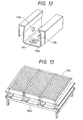
- a retaining clip 1104 as shown in Fig. 12, has a through hole 1105 through which a screw for fixing the retaining clip to the rafter passes, a mating portion 1106 to which a screw for making the electric conduction surer to the combination solar cell and roof member is attached, and a further mating portion 1107 to which a screw for making conduction sure to the metal conductive portion provided on the rafter is attached. After the module was fixed, the screws were attached to the mating portions 1106, 1107 of the retaining clip 1104.
- the roof members of the present example realized the mounting of combination solar cell and roof members and the electric grounding of the metal outside portions of combination solar cell and roof members with high work efficiency and at low cost, in the same manner as in Example 1, and they were the roof members also excellent in terms of the external view. Further, utilization of the wood rafters realized the roof members with higher work efficiency and at lower cost of installation in wood-structure houses normally using such rafters.
- the roof members of the present example are those to be installed by a roof mounting method, so called a batten seam roofing method with batten, for the ordinary metal roof members.
- the combination solar cell and roof members used in the present example were prepared in the same manner as in Example 1.
- Fig. 15 is a cross-sectional, structural view of the roof members of the present example.
- Batten 1502 was mounted on sheathing roof board 1506.
- the sheathing roof board 1506 was provided with notches in portions overlapping with the terminal lead-out portions located on the back side of combination solar cell and roof member, and serial connection of outputs from the solar cells through cables was made possible through the notch portions.
- the batten 1502 is covered with a stainless steel sheet of a U-shape as a metal member 1503 for conduction to the combination solar cell and roof members 1501.
- the combination solar cell and roof members 1501 were placed between battens 1502, and nails 1505 were put into the batten 1502 through the combination solar cell and roof member 1501 and the metal member 1503 to fix them.
- Decorative cover 1504 was mounted finally.
- the cable was attached to the metal member at the ridge-side edge of the roof.
- the electric conduction was achieved from the metal reinforcing members of the combination solar cell and roof members through the nails to the metal member incorporated with the batten, and the cable was finally guided into the interior, thus achieving the electric grounding lastly.
- the metal members incorporated with the battens made possible the electric conduction of the all combination solar cell and roof members arranged from the ridge to the eaves, and the roof members of the present example realized the installation and electric grounding of the metal reinforcing members of individual combination solar cell and roof members with high work efficiency and at low cost, in the same manner as in Example 1, while being the roof members also excellent in terms of the external view.
- the battens were incorporated with the metal sheet, and utilization thereof permitted the roof members to be fixed by nailing popularly used for the roofs, thus further increasing the work efficiency.
- the roof members of the present example are those installed by a roof mounting method, called a batten seam roofing method, for the ordinary metal roof members.
- the combination solar cell and roof members were prepared in the same manner as in Example 1.
- Fig. 16 is a cross-sectional, structural view of the roof members of the present example.
- the sheathing roof board 1606 was laid on the rafters.
- the sheathing roof board 1606 was provided with notches in terminal lead-out portions located on the back side of combination solar cell and roof member 1601, thereby enabling serial connection of outputs from the solar cells with cables through the notch portions.
- the combination solar cell and roof members 1601 were placed on the sheathing roof board.
- the combination solar cell and roof members 1601 were retained by through retaining clips 1602 of stainless steel integrally formed from the ridge edge to the eave edge of roof and were fixed with screws 1603.
- the retaining clips were fixed to the sheathing roof board 1606 with tapping screws 1604.
- the cables was attached to the metal member at the ridge-side edge of the roof and the other end of the cable was guided into the interior to be electrically grounded.
- the decorative cover 1605 was finally attached thereover.
- the roof members of the present example realized the mounting of combination solar cell and roof members and the electric grounding of the metal reinforcing members of combination solar cell and roof members with high work efficiency and at low cost, in the same manner as in Example 1, and they were the roof members also excellent in terms of the external view.
- the present invention provided the cheap combination solar cell and roof member array easy to install and excellent in the external view and electric safety by adopting the above means.
- the metal member was provided below the combination solar cell and roof member or in the adjacent portion between the solar cells and the metal reinforcing members of combination solar cell and roof members were electrically grounded through the metal members for electric conduction, whereby each of the combination solar cell and roof members was able to be electrically grounded without a need for use of many cables.
- the metal sheet was placed as the metal member for electric conduction, whereby the metal member was able to be placed even if there was little space around the combination solar cell and roof member. Since the metal sheet is readily available, cheap, high in durability, and applicable without special processing, the invention made it possible to place the metal members for electric grounding with high work efficiency and at low cost.
- the metal rafters are generally used as structural members in buildings having the substrate structure such as the reinforcement structure.
- the electric grounding through this metal rafter obviated the need for placement of separate metal members for electric conduction.
- the roof members became excellent in terms of the cost, work efficiency, and external view.
- combination solar cell and roof member When the combination solar cell and roof member was fixed by the retaining clips, there arose no problem of stress concentration on the bolted part of combination solar cell and roof member. This obviated the need for use of a heavy frame as a mount to the framework. It also became possible to fix the combination solar cell and roof member without any processing such as forming bolt holes in the combination solar cell and roof member. As a result, the arrangement made possible the weight reduction and cost reduction of combination solar cell and roof member.
- the metal roof members having been used heretofore as roof members are generally installed using engagement and retaining clips in the same manner as in the above fixing method.
- the shape of combination solar cell and roof member was made closer to the shape of these conventional metal roof members, which enhanced commonality of fixing method, commonality of accessories, etc. and which realized the roof members improved in work efficiency and having the excellent external view. It also made possible mixed roofing of the combination solar cell and roof members and the ordinary metal roof members.
- a part of retaining clip was conductive and the electric conduction was achieved through the retaining clip between the metal reinforcing member of combination solar cell and roof member and the metal member laid on the roof substrate, whereby the electric conduction was attained without use of a cable between the combination solar cell and roof member and the metal member, thus realizing the roof members at low cost and with high work efficiency.
- the retaining clip had the conductive screw and electric conduction was achieved among the metal reinforcing member of combination solar cell and roof member, the screw, and the conductive part of retaining clip, whereby the electric conduction was made surer between the metal outside portion of combination solar cell and roof member and the retaining clip.
- the metal reinforcing member was the metal frame member provided in at least a part of the circumference of combination solar cell and roof member, the sufficient strength was attained for the solar cell to be used as a roof member.
- the roof members were able to be formed in the shape similar to the conventional metal roof and the combination solar cell and roof members were excellent in terms of the strength of the roof, the external view, and the work efficiency.
- the combination solar cell and roof members were able to be mounted without a seam to the frame, were excellent in flashing, and were light in weight, so that the combination solar cell and roof members were those imparting no heavy load on the building and having high work efficiency of installation.
- Roof members of the present invention are those fixed to the roof, each roof member being a combination solar cell and roof member having a solar cell element and a metal reinforcing member, wherein a metal member is provided below the combination solar cell and roof member or a metal member is provided along an adjacent portion between adjacent combination solar cell and roof members, wherein the metal member is electrically conductive to metal reinforcing members of plural combination solar cell and roof members and wherein the metal member is electrically grounded.
- the roof members easy to install and excellent in the external view and electric safety.
Landscapes
- Engineering & Computer Science (AREA)
- Mechanical Engineering (AREA)
- Architecture (AREA)
- Civil Engineering (AREA)
- Structural Engineering (AREA)
- Physics & Mathematics (AREA)
- Life Sciences & Earth Sciences (AREA)
- Sustainable Development (AREA)
- Sustainable Energy (AREA)
- Thermal Sciences (AREA)
- Chemical & Material Sciences (AREA)
- Combustion & Propulsion (AREA)
- General Engineering & Computer Science (AREA)
- Roof Covering Using Slabs Or Stiff Sheets (AREA)
- Photovoltaic Devices (AREA)
Claims (28)
- Kombination aus einem Dachelement (101; 1501; 1601) und einem leitfähigen Element, wobei das Dachelement (101; 1501; 1601) eine Solarzelle und ein Metallverstärkungselement aufweist, wobei das Metallverstärkungselement an zumindest einem leitfähigen Element angeordnet ist, wobei das leitfähige Element mit dem Metallverstärkungselement durch eine Halteklemmeinrichtung (105), von der zumindest ein Teil eine elektrisch leitfähige Eigenschaft hat, elektrisch verbunden ist,
dadurch gekennzeichnet, dass
das leitfähige Element derart elektrisch geerdet ist, dass das Dachelement (101; 1501; 1601) über das leitfähige Element geerdet ist, und
die Halteklemmeinrichtung (105) einen Passabschnitt aufweist, eine Schraube (113; 515; 1603) das Metallverstärkungselement gegen die Halteklemmeinrichtung (105) in dem Passabschnitt drängt, wobei die Schraube elektrisch leitfähige Eigenschaften hat und so befestigt ist, dass sie mit dem Metallverstärkungselement in Kontakt steht, und eine elektrische Leitung zwischen dem Metallverstärkungselement, der Schraube (113; 515; 1603) und dem leitfähigen Abschnitt der Halteklemmeinrichtung (105) erzielt wird. - Kombination gemäß Anspruch 1, wobei
das leitfähige Element ein Metallblech (1002) ist. - Kombination gemäß Anspruch 2, wobei
das Metallblech (1002) an einem Holzsparren (1001) montiert ist. - Kombination gemäß Anspruch 1, wobei
das leitfähige Element ein Metallsparren (108; 508) ist. - Kombination gemäß einem der vorherigen Ansprüche, wobei
die Halteklemmeinrichtung (105) eine Metallhalteklemmeinrichtung (105) ist, wobei die Metallhalteklemmeinrichtung (105) einen Eingriffsabschnitt in einer Hakenform aufweist, um das Metallverstärkungselement, einen Fixierabschnitt, der an einem Dachsubstrat zu fixieren ist, und einen Passabschnitt, an dem eine Metallschraube (113; 515; 1603) befestigt ist, zu halten,
wobei ein Abschnitt, der das Metallverstärkungselement aufweist, zwischen dem Eingriffsabschnitt der Halteklemmeinrichtung (105) und dem Dachsubstrat sandwichartig angeordnet ist, wobei die Halteklemmeinrichtung (105) an dem Dachsubstrat an dem Fixierabschnitt fixiert ist, wobei das Endstück der Metallschraube (113; 515; 1603), die an der Halteklemmeinrichtung (105) befestigt ist, in dem Zustand eines festen Kontaktes mit dem Metallverstärkungselement ist, und wobei das Metallverstärkungselement und die Halteklemmeinrichtung (105) durch die Metallschraube (113; 515; 1603) elektrisch leitfähig gestaltet sind. - Kombination gemäß einem der vorherigen Ansprüche, wobei
das Metallverstärkungselement ein Metallrahmenelement (1405) ist, das an zumindest einem Abschnitt des Umfangs des Dachelementes (101; 1501; 1601) vorgesehen ist. - Kombination gemäß einem der Ansprüche 1 bis 5, wobei
das Metallverstärkungselement ein Metallblech (1002) ist, das an der Bodenseite des Dachelementes (101; 1501; 1601) vorgesehen ist. - Kombination gemäß Anspruch 7, wobei
das Dachelement (101; 1501; 1601) einen Eingriffsabschnitt aufweist, der durch ein plastisches Bearbeiten des Metallbleches (1002) in einem nicht Energie erzeugenden Bereich erhalten worden ist, wobei der Eingriffsabschnitt zumindest einen Abschnitt aufweist, der keinen Isolationsfilm hat, wobei das Metallblech (1002) mit dem leitfähigen Element, das an dem Dachsubstrat vorgesehen ist, zumindest durch den Abschnitt, der den Isolationsfilm nicht aufweist, elektrisch leitfähig gestaltet ist. - Kombination aus einem Dachelement (501) und einem leitfähigen Element, wobei das Dachelement (501) eine Solarzelle und ein Metallverstärkungselement aufweist, wobei eine Vielzahl der Dachelemente (501) benachbart zu zumindest einem gemeinsamen leitfähigen Element angeordnet sind, wobei das leitfähige Element mit den Metallverstärkungselementen elektrisch verbunden ist,
dadurch gekennzeichnet, dass
das leitfähige Element derart elektrisch geerdet ist, dass die Dachelemente (501) über das leitfähige Element geerdet sind,
wobei das leitfähige Element eine lange Halteklemmeinrichtung (505; 1104) ist, die die Dachelemente (501) benachbart zueinander fixiert, und
das leitfähige Element eine Schraube (113; 515; 1603) aufweist, die eine elektrisch leitfähige Eigenschaft hat, wobei die Schraube (113; 515; 1603) so befestigt ist, dass sie mit dem Metallverstärkungselement in Kontakt steht, und eine elektrische Leitung zwischen dem Metallverstärkungselement, der Schraube (113; 515; 1603) und dem leitfähigen Element erhalten wird. - Kombination gemäß Anspruch 9, wobei
das leitfähige Element ein Metallblech (1002) ist, das zwischen den Elementen angeordnet ist. - Kombination gemäß Anspruch 9 oder 10, wobei
das leitfähige Element so vorgesehen ist, dass es einen benachbarten Abschnitt bedeckt. - Kombination gemäß einem der Ansprüche 9 bis 11, wobei
das Metallverstärkungselement ein Metallrahmenelement (1405) ist, das an zumindest einem Teil des Umfangs des Dachelementes (501) vorgesehen ist. - Kombination gemäß einem der Ansprüche 9 bis 11, wobei
das Metallverstärkungselement ein Metallblech (1002) ist, das an der Bodenseite des Dachelementes (501) vorgesehen ist. - Kombination gemäß Anspruch 13, wobei
das Dachelement (501) einen Eingriffsabschnitt aufweist, der durch ein plastisches Bearbeiten des Metallbleches (1002) in einem keine Energie erzeugenden Bereich erhalten worden ist, wobei der Eingriffsabschnitt zumindest einen Isolationsfilm aufweist, wobei das Metallblech (1002) mit dem leitfähigen Element zumindest durch den Abschnitt, der den Isolationsfilm nicht aufweist, elektrisch leitfähig gestaltet ist. - Verfahren zur Montage einer Kombination aus einem Dachelement (101; 1501; 1601) und einem leitfähigen Element, wobei das Dachelement (101; 1501; 1601) eine Solarzelle und ein Metallverstärkungselement aufweist,
wobei das Verfahren die folgenden Schritte aufweist: einen Schritt zum Vorsehen des leitfähigen Elementes an einem Dachsubstrat, einen Schritt zum Montieren des Dachelementes (101; 1501; 1601) an dem leitfähigen Element, einen Schritt, bei dem das leitfähige Element mit dem Metallverstärkungselement elektrisch leitfähig gestaltet wird, und einen Schritt zum elektrischen Erden des leitfähigen Elementes, wobei in Bezug auf das Dachelement (101; 1501; 1601) zumindest eine Halteklemmeinrichtung (105) für das Dachelement (101; 1501; 1601) vorhanden ist, wobei ein Teil der Halteklemmeinrichtung (105) elektrisch leitfähig ist, und
wobei das Metallverstärkungselement und das leitfähige Element, das an dem Dachsubstrat vorgesehen wird, durch die Halteklemmeinrichtung (105) elektrisch leitfähig gestaltet werden,
dadurch gekennzeichnet, dass
die Halteklemmeinrichtung (105) eine Schraube (113; 515; 1603) mit einer elektrisch leitfähigen Eigenschaft aufweist, und wobei die Schraube (113; 515; 1603) so befestigt wird, dass sie mit dem Metallverstärkungselement in Kontakt steht, und wobei eine elektrische Leitung zwischen dem Metallverstärkungselement, der Schraube (113; 515; 1603) und dem leitfähigen Element erzielt wird, und dass das leitfähige Element elektrisch geerdet wird. - Verfahren gemäß Anspruch 15, wobei
das leitfähige Element ein Metallblech (1002) ist. - Verfahren gemäß Anspruch 16, wobei
das Metallblech (1002) an einem Dachsparren (1101) montiert wird. - Verfahren gemäß Anspruch 15, wobei
das leitfähige Element ein Metallsparren (108; 508) ist. - Verfahren gemäß einem der vorherigen Ansprüche, wobei
die Halteklemmeinrichtung (505) eine Metallhalteklemmeinrichtung (505) ist, wobei die Metallhalteklemmeinrichtung (105) einen Eingriffsabschnitt in einer Hakenform aufweist, um das Dachelement (101; 1501; 1601), einen Fixierabschnitt, der an einem Dachsubstrat zu fixieren ist, und einen Passabschnitt (113), an dem eine Metallschraube (113; 515; 1603) befestigt ist, zu halten,
wobei ein Abschnitt, der das Metallverstärkungselement aufweist, zwischen dem Eingriffsabschnitt der Halteklemmeinrichtung (105) und dem Dachsubstrat sandwichartig angeordnet wird, und wobei die Halteklemmeinrichtung (105) an dem Dachsubstrat an dem Fixierabschnitt so fixiert wird, dass das Endstück der Metallschraube (113; 515; 1603), die an der Halteklemmeinrichtung (105) befestigt ist, in einem Zustand eines festen Kontaktes mit dem Metallverstärkungselement ist,
wobei das Metallverstärkungselement und die Halteklemmeinrichtung (105) durch die Metallschraube (113; 515; 1603) elektrisch leitfähig gestaltet sind. - Verfahren gemäß einem der Ansprüche 15 bis 19, wobei
das Metallverstärkungselement ein Metallrahmenelement (1405) ist, das an zumindest einem Abschnitt des Umfangs des Dachelementes (101; 1501; 1601) vorgesehen wird. - Verfahren gemäß einem der Ansprüche 15 bis 19, wobei
das Metallverstärkungselement ein Metallblech (1002) ist, das an der Bodenseite des Dachelementes (101; 1501; 1601) vorgesehen wird. - Verfahren gemäß Anspruch 21, wobei
das Dachelement (101; 1501; 1601) einen Eingriffsabschnitt aufweist, der durch ein plastisches Bearbeiten des Metallblechs (1002) in einem keine Energie erzeugenden Bereich erhalten wird, wobei der Eingriffsabschnitt des Dachelementes (101; 1501; 1601) zumindest einen Abschnitt aufweist, der keinen Isolationsfilm hat, wobei das Metallblech (1002) mit dem leitfähigen Element, das an dem Dachsubstrat vorgesehen ist, zumindest durch den Teil, der den Isolationsfilm nicht aufweist, elektrisch leitfähig gestaltet wird. - Verfahren zum Montieren einer Kombination aus einem Dachelement (501) und einem leitfähigen Element, wobei das Dachelement (501) eine Solarzelle und ein Metallverstärkungselement aufweist, wobei eine Vielzahl der Dachelemente (501) benachbart zu zumindest einem gemeinsamen leitfähigen Element angeordnet werden, wobei das leitfähige Element mit den Metallverstärkungselementen elektrisch verbunden wird, und wobei das leitfähige Element elektrisch geerdet wird,
dadurch gekennzeichnet, dass
das leitfähige Element eine lange Halteklemmeinrichtung (505; 1104) ist, die die Dachelemente (501) benachbart zueinander fixiert, und
wobei das leitfähige Element eine Schraube (113, 515; 1603) aufweist, die eine elektrisch leitfähige Eigenschaft hat, und wobei die Schraube (113; 515; 1603) so befestigt wird, dass sie mit dem Metallverstärkungselement in Kontakt steht, und wobei eine elektrische Leitung zwischen dem Metallverstärkungselement, der Schraube (113; 515; 1603) und dem leitfähigen Element erzielt wird, und wobei das leitfähige Element elektrisch geerdet wird. - Verfahren gemäß Anspruch 23, wobei
das leitfähige Element ein Metallblech (1002) ist, das zwischen den Dachelementen (501) angeordnet wird. - Verfahren gemäß Anspruch 23 oder 24, wobei
das leitfähige Element so vorgesehen wird, dass es einen benachbarten Abschnitt bedeckt. - Verfahren gemäß einem der Ansprüche 23 bis 25, wobei
das Metallverstärkungselement ein Metallrahmenelement (1405) ist, das an zumindest einem Abschnitt des Umfangs des Dachelementes (501) vorgesehen wird. - Verfahren gemäß einem der Anspruche 23 bis 25, wobei
das Metallverstärkungselement ein Metallblech (1002) ist, das an der Bodenseite des Dachelementes (501) vorgesehen wird. - Verfahren gemäß Anspruch 27, wobei
das Dachelement (501) einen Eingriffsabschnitt aufweist, der durch ein plastisches Bearbeiten des Metallbleches (1002) in einem keine Energie erzeugenden Bereich erhalten wird, wobei der Eingriffsabschnitt zumindest einen Abschnitt ohne Isolationsfilm aufweist,
wobei das Metallblech (1002) mit dem leitfähigen Element zumindest durch den Teil, der den Isolationsfilm nicht aufweist, elektrisch leitfähig gestaltet wird.
Applications Claiming Priority (3)
| Application Number | Priority Date | Filing Date | Title |
|---|---|---|---|
| JP02261397A JP3610178B2 (ja) | 1997-02-05 | 1997-02-05 | 屋根及びその施工方法 |
| JP22613/97 | 1997-02-05 | ||
| JP2261397 | 1997-02-05 |
Publications (3)
| Publication Number | Publication Date |
|---|---|
| EP0858115A2 EP0858115A2 (de) | 1998-08-12 |
| EP0858115A3 EP0858115A3 (de) | 1999-07-14 |
| EP0858115B1 true EP0858115B1 (de) | 2007-12-19 |
Family
ID=12087698
Family Applications (1)
| Application Number | Title | Priority Date | Filing Date |
|---|---|---|---|
| EP98101909A Expired - Lifetime EP0858115B1 (de) | 1997-02-05 | 1998-02-04 | Dachelement mit einer Solarzelle und Einbauverfahren |
Country Status (7)
| Country | Link |
|---|---|
| US (1) | US6269596B1 (de) |
| EP (1) | EP0858115B1 (de) |
| JP (1) | JP3610178B2 (de) |
| KR (1) | KR100276196B1 (de) |
| CN (1) | CN1194154C (de) |
| AU (1) | AU748065B2 (de) |
| DE (1) | DE69838861T2 (de) |
Families Citing this family (138)
| Publication number | Priority date | Publication date | Assignee | Title |
|---|---|---|---|---|
| US7012188B2 (en) * | 2000-04-04 | 2006-03-14 | Peter Stuart Erling | Framing system for solar panels |
| JP3605032B2 (ja) * | 2000-06-07 | 2004-12-22 | 三洋電機株式会社 | 太陽電池モジュール,太陽電池モジュールの接続方法,太陽電池モジュールの設置方法及び太陽電池モジュールのアース接続方法 |
| US7434362B2 (en) * | 2001-07-20 | 2008-10-14 | Unirac, Inc. | System for removably and adjustably mounting a device on a surface |
| JPWO2003029577A1 (ja) * | 2001-09-28 | 2005-01-20 | 株式会社カネカ | 太陽電池モジュール、太陽電池モジュールの敷設方法及び太陽電池モジュールの吹上げ防止装置 |
| US6617507B2 (en) | 2001-11-16 | 2003-09-09 | First Solar, Llc | Photovoltaic array |
| JP2004006702A (ja) | 2002-03-28 | 2004-01-08 | Canon Inc | 太陽電池モジュール設置構造体、太陽電池モジュールアレイ及び太陽光発電システム |
| US7600349B2 (en) | 2003-02-26 | 2009-10-13 | Unirac, Inc. | Low profile mounting system |
| US6959517B2 (en) * | 2003-05-09 | 2005-11-01 | First Solar, Llc | Photovoltaic panel mounting bracket |
| US20050217716A1 (en) * | 2004-01-29 | 2005-10-06 | Kyocera Corporation | Photovoltaic power generation system |
| US7592537B1 (en) | 2004-02-05 | 2009-09-22 | John Raymond West | Method and apparatus for mounting photovoltaic modules |
| US7856769B2 (en) * | 2004-02-13 | 2010-12-28 | Pvt Solar, Inc. | Rack assembly for mounting solar modules |
| US8344239B2 (en) * | 2004-02-13 | 2013-01-01 | Pvt Solar, Inc. | Mechanism for mounting solar modules |
| US7406800B2 (en) * | 2004-05-18 | 2008-08-05 | Andalay Solar, Inc. | Mounting system for a solar panel |
| US20060037280A1 (en) * | 2004-07-30 | 2006-02-23 | Smith Charles L Jr | Metal roof system |
| US20090038668A1 (en) * | 2007-08-08 | 2009-02-12 | Joshua Reed Plaisted | Topologies, systems and methods for control of solar energy supply systems |
| PL1896785T3 (pl) * | 2005-06-24 | 2014-04-30 | Vkr Holding As | Kolektor słoneczny |
| US8196360B2 (en) * | 2006-01-12 | 2012-06-12 | Msr Innovations Inc. | Photovoltaic solar roof tile assembly system |
| WO2007137199A2 (en) * | 2006-05-18 | 2007-11-29 | Pvt Solar, Inc. | Interconnected solar module design and system |
| US20070284077A1 (en) * | 2006-05-29 | 2007-12-13 | Matteo B. Gravina | Smart Solar Roof |
| US20070289249A1 (en) * | 2006-06-16 | 2007-12-20 | David Martel | L-shape slotted deck board and hidden fastener system |
| US7814899B1 (en) * | 2006-07-04 | 2010-10-19 | Jonathan Port | Solar panel mounting systems |
| WO2008028151A2 (en) * | 2006-08-31 | 2008-03-06 | Pvt Solar, Inc. | Technique for electrically bonding solar modules and mounting assemblies |
| US7721492B2 (en) * | 2006-09-06 | 2010-05-25 | Pvt Solar, Inc. | Strut runner member and assembly using same for mounting arrays on rooftops and other structures |
| US7857269B2 (en) * | 2006-11-29 | 2010-12-28 | Pvt Solar, Inc. | Mounting assembly for arrays and other surface-mounted equipment |
| FR2915345B1 (fr) * | 2007-04-20 | 2009-07-03 | Imphy Alloys Sa | Bati support d'un panneau electriquement actif tel qu'un panneau photovoltaique |
| WO2009032862A2 (en) * | 2007-09-03 | 2009-03-12 | Robert Stancel | Mounting system for solar modules |
| US8813460B2 (en) * | 2007-09-21 | 2014-08-26 | Andalay Solar, Inc. | Mounting system for solar panels |
| US8505248B1 (en) | 2007-09-21 | 2013-08-13 | Andalay Solar, Inc. | Minimal ballasted surface mounting system and method |
| US8938919B2 (en) * | 2007-09-21 | 2015-01-27 | Andalay Solar, Inc. | Electrical connectors for solar modules |
| FR2924141B1 (fr) * | 2007-11-27 | 2012-08-17 | Qualitelec | Dispositif support de panneau de couverture de toiture |
| US20090159118A1 (en) * | 2007-12-19 | 2009-06-25 | Kalkanoglu Husnu M | Roofing Products Having Receptor Zones and Photovoltaic Roofing Elements and Systems Using Them |
| KR101467600B1 (ko) * | 2008-02-11 | 2014-12-05 | 존 알. 웨스트 | 광전지 어레이를 형성 및 장착하기 위한 방법 및 장치 |
| US20090230265A1 (en) * | 2008-03-17 | 2009-09-17 | Michael Newman | Mounting System for Photovoltaic Panels |
| CA2761367A1 (en) | 2008-05-08 | 2009-11-12 | Solar Power, Inc. | Flat roof mounted solar panel support system |
| US8677701B2 (en) * | 2008-09-25 | 2014-03-25 | The Boeing Company | Attaching solar collectors to a structural framework utilizing a flexible clip |
| EP2350535A4 (de) * | 2008-10-11 | 2014-01-22 | Solar Power Inc | Solarzellensysteme mit effizienter installation |
| JP4511616B2 (ja) * | 2008-11-05 | 2010-07-28 | シャープ株式会社 | 太陽電池モジュールの架台及びそれを用いた太陽光発電システム |
| EP2194342A3 (de) * | 2008-12-05 | 2011-07-20 | Climasol-Solaranlagen GmbH | Gleitschuh |
| DE102009026084A1 (de) * | 2008-12-05 | 2010-06-17 | Climasol-Solaranlagen Gmbh | System zur Befestigung eines Solarmoduls |
| US8732940B2 (en) * | 2009-03-12 | 2014-05-27 | Clean Energy Solutions, Inc. | System and method for mounting photovoltaic panels |
| US8316593B2 (en) * | 2009-03-18 | 2012-11-27 | Garland Industries, Inc. | Solar roofing system |
| US20110220596A1 (en) * | 2009-03-20 | 2011-09-15 | Northern States Metals Company | Support system for solar panels |
| CA2756664A1 (en) | 2009-03-24 | 2010-09-30 | Certainteed Corporation | Photovoltaic systems, methods for installing photovoltaic systems, and kits for installing photovoltaic systems |
| US8294022B2 (en) * | 2009-04-01 | 2012-10-23 | Sunpower Corporation | Photovoltaic array with minimally penetrating rooftop support system |
| US8991114B2 (en) | 2009-07-02 | 2015-03-31 | Zep Solar, Llc | Pivot-fit connection apparatus, system, and method for photovoltaic modules |
| US9518596B2 (en) | 2009-07-02 | 2016-12-13 | Solarcity Corporation | Pivot-fit frame, system and method for photovoltaic modules |
| EP2449599B1 (de) | 2009-07-02 | 2018-08-15 | SolarCity Corporation | Vorrichtung zur nivellierung von photovoltaikanlagen |
| US20120298188A1 (en) | 2009-10-06 | 2012-11-29 | Zep Solar, Inc. | Method and Apparatus for Forming and Mounting a Photovoltaic Array |
| US20110114158A1 (en) * | 2009-11-16 | 2011-05-19 | Sunpower Corporation | Replaceable photovoltaic roof panel |
| US8196369B2 (en) * | 2010-01-28 | 2012-06-12 | Frank Pao | Building integrated thermal electric hybrid roofing system |
| US10054336B2 (en) | 2010-03-03 | 2018-08-21 | Robert M. M. Haddock | Photovoltaic module mounting assembly |
| KR101142166B1 (ko) | 2010-04-19 | 2012-05-07 | 주식회사 건기 | 솔라셀 설치용 구조물 |
| USD649929S1 (en) | 2010-04-20 | 2011-12-06 | Solar Power, Inc. | Photovoltaic structure |
| EP2390924A1 (de) * | 2010-05-26 | 2011-11-30 | Thesan S.p.A. | Gebäudedach mit Zeilen von gewellten Ziegeln alternierend mit streifenförmigen Solarmodulen und Paneel aus Metallblech zur Herstellung dieses Daches |
| US20110314751A1 (en) * | 2010-06-29 | 2011-12-29 | Roger Jette | Solar panel mounting rack system |
| USD759464S1 (en) | 2010-07-02 | 2016-06-21 | Solarcity Corporation | Leveling foot |
| US20130125492A1 (en) * | 2010-07-26 | 2013-05-23 | Efraim Molek | Locking mechanism for panels |
| US8677702B2 (en) | 2010-09-28 | 2014-03-25 | Certainteed Corporation | Photovoltaic systems, methods for installing photovoltaic systems, and kits for installing photovoltaic systems |
| CA2816562A1 (en) * | 2010-10-05 | 2012-04-12 | Dynoraxx, Inc. | Mount for pitched roof and method of use |
| CN102468348A (zh) * | 2010-11-16 | 2012-05-23 | 杜邦太阳能有限公司 | 光伏组件安装装置 |
| WO2012079060A2 (en) | 2010-12-09 | 2012-06-14 | Zep Solar, Inc. | Pivot-fit connection apparatus and system for photovoltaic arrays |
| WO2012079061A1 (en) | 2010-12-09 | 2012-06-14 | Zep Solar, Inc. | Skirt for photovoltaic arrays |
| US8365500B2 (en) | 2010-12-22 | 2013-02-05 | Frank Pao | Optimized building integrated hybrid roofing system |
| US8201382B1 (en) | 2010-12-22 | 2012-06-19 | Frank Pao | Building integrated thermal electric hybrid roofing system |
| EP2736380A2 (de) * | 2011-02-09 | 2014-06-04 | Solar Liberty Energy Systems Inc. | Sandwichkeilklemme zur befestigung eines solarmoduls |
| US8839573B2 (en) | 2011-02-11 | 2014-09-23 | Northern States Metals Company | Spring clip |
| WO2012116121A1 (en) | 2011-02-22 | 2012-08-30 | Zep Solar, Inc. | Pivot-fit frame, system and method for photovoltaic modules |
| US9611652B2 (en) | 2011-02-25 | 2017-04-04 | Dustin M. M. Haddock | Mounting device for building surfaces having elongated mounting slot |
| USD668214S1 (en) | 2011-04-27 | 2012-10-02 | Blue Sunny Skies Llc | Grounding clip |
| US9091461B2 (en) | 2011-04-27 | 2015-07-28 | Blue Sunny Skies Llc | Grounding system for photovoltaic arrays |
| TWI422789B (zh) * | 2011-04-28 | 2014-01-11 | Au Optronics Corp | 太陽能裝置 |
| WO2012170799A2 (en) | 2011-06-09 | 2012-12-13 | A. Raymond Et Cie | Solar panel attachment system for a roof |
| US8567742B2 (en) | 2011-07-22 | 2013-10-29 | Aquatherm Industries, Inc. | Mounting bracket protection device |
| CN102956727A (zh) * | 2011-08-26 | 2013-03-06 | 杜邦太阳能有限公司 | 夹持装置及具有其的太阳能模块 |
| US8590223B2 (en) | 2011-08-29 | 2013-11-26 | A. Raymond Et Cie | Solar panel assembly attachment apparatus |
| US8894424B2 (en) | 2011-08-29 | 2014-11-25 | A. Raymond Et Cie | Universal clip apparatus for solar panel assembly |
| US8745935B2 (en) * | 2011-10-14 | 2014-06-10 | A. Raymond Et Cie | Photovoltaic panel fastening system |
| USD765591S1 (en) | 2011-12-09 | 2016-09-06 | Solarcity Corporation | Panel skirt and photovoltaic panel |
| US20130168525A1 (en) | 2011-12-29 | 2013-07-04 | Dustin M.M. Haddock | Mounting device for nail strip panels |
| US8713881B2 (en) | 2012-01-27 | 2014-05-06 | A. Raymond Et Cie | Solar panel securing system |
| JP5963463B2 (ja) * | 2012-02-02 | 2016-08-03 | シャープ株式会社 | 太陽電池モジュールの設置構造、太陽電池モジュールの設置方法、太陽電池モジュール設置用桟、及び太陽光発電システム |
| US9320926B2 (en) | 2012-06-28 | 2016-04-26 | Solarcity Corporation | Solar panel fire skirt |
| US8567134B1 (en) * | 2012-06-29 | 2013-10-29 | Sunpower Corporation | Snap-in and progressive locking photovoltaic module |
| US9331629B2 (en) | 2012-07-02 | 2016-05-03 | A. Raymond Et Cie | Photovoltaic frame fastener |
| US9051950B2 (en) | 2012-08-08 | 2015-06-09 | Thomas & Betts International, Inc. | Universal panel clamp |
| WO2014039967A1 (en) | 2012-09-07 | 2014-03-13 | Advanced Solar Products, Inc. | Pre-assembled solar panel mounting system |
| US20150226247A1 (en) * | 2012-09-28 | 2015-08-13 | Dow Global Technologies Llc | Roof panel edge support |
| US10008975B2 (en) | 2012-12-10 | 2018-06-26 | Nextracker Inc. | Clamp assembly for solar tracker |
| CN109713991B (zh) | 2012-12-10 | 2020-05-29 | 耐克斯特拉克尔有限公司 | 跟踪器设备 |
| US9466749B1 (en) | 2012-12-10 | 2016-10-11 | Nextracker Inc. | Balanced solar tracker clamp |
| US9766319B2 (en) | 2012-12-10 | 2017-09-19 | Nextracker Inc. | Off-set drive assembly for solar tracker |
| DE202012012462U1 (de) * | 2012-12-20 | 2013-03-04 | Mounting Systems Gmbh | Befestigungssystem zur Montage von Solarmodulen |
| WO2014134191A1 (en) * | 2013-02-26 | 2014-09-04 | Zep Solar, Inc. | Torque tube mounted photovoltaic apparatus, system, and method |
| US9147785B2 (en) | 2013-03-15 | 2015-09-29 | Robert M. M. Haddock | Slide fit mounting clip for installing photovoltaic modules |
| US9068764B2 (en) * | 2013-04-10 | 2015-06-30 | Stion Corporation | Method and apparatus for clamping frameless thin-film solar module |
| US9303663B2 (en) | 2013-04-11 | 2016-04-05 | Northern States Metals Company | Locking rail alignment system |
| KR101368923B1 (ko) * | 2013-04-24 | 2014-03-04 | (주)에이비엠그린텍 | 태양전지모듈을 마감재로 사용하는 지붕패널 |
| US10432132B2 (en) | 2013-07-01 | 2019-10-01 | RBI Solar, Inc. | Solar mounting system having automatic grounding and associated methods |
| US9080792B2 (en) | 2013-07-31 | 2015-07-14 | Ironridge, Inc. | Method and apparatus for mounting solar panels |
| US9515599B2 (en) | 2013-09-17 | 2016-12-06 | Lumos Lsx, Llc | Photovoltaic panel mounting rail with integrated electronics |
| US10063183B2 (en) | 2013-11-21 | 2018-08-28 | Patton Engineering, Inc. | Solar panel with pivoting side supports |
| US8938932B1 (en) * | 2013-12-13 | 2015-01-27 | Quality Product Llc | Rail-less roof mounting system |
| US20150184896A1 (en) * | 2014-01-02 | 2015-07-02 | RI Enterprises, LLC | Solar panel support apparatus |
| TWI586878B (zh) | 2014-09-12 | 2017-06-11 | 上銀光電股份有限公司 | 波紋屋頂薄片及包含此波紋屋頂薄片的光伏組件 |
| CN104617856A (zh) * | 2015-01-16 | 2015-05-13 | 镇江大全能源设备有限公司 | 一种光伏支架彩钢瓦型材及夹具 |
| US9748892B2 (en) * | 2015-07-27 | 2017-08-29 | Solarcity Corporation | Clip-in mounting system for photovoltaic systems |
| JP6533730B2 (ja) * | 2015-10-02 | 2019-06-19 | 日栄インテック株式会社 | 支持装置 |
| US10673373B2 (en) | 2016-02-12 | 2020-06-02 | Solarcity Corporation | Building integrated photovoltaic roofing assemblies and associated systems and methods |
| US10443896B2 (en) | 2016-07-29 | 2019-10-15 | Rmh Tech Llc | Trapezoidal rib mounting bracket with flexible legs |
| WO2018081722A1 (en) | 2016-10-31 | 2018-05-03 | Haddock Dustin M M | Metal panel electrical bonding clip |
| CN106452305B (zh) * | 2016-11-16 | 2018-11-23 | 海宁创源太阳能科技有限公司 | 一种太阳能电池板安装支架及其安装方法 |
| US10305417B1 (en) * | 2017-03-20 | 2019-05-28 | James Tanghongs | Support mount for rooftop solar panels |
| AU2018348090B2 (en) | 2017-10-09 | 2021-11-18 | Rmh Tech Llc | Rail assembly with invertible side-mount adapter for direct and indirect mounting applications |
| CN107762074B (zh) * | 2017-11-10 | 2023-09-08 | 中铁第四勘察设计院集团有限公司 | 提高抗风揭性能的双层屋面系统 |
| CN107780599A (zh) * | 2017-11-10 | 2018-03-09 | 上海安特迈思建筑系统科技有限公司 | 一种屋面板固定支座 |
| CN107842147A (zh) * | 2017-11-10 | 2018-03-27 | 中铁第四勘察设计院集团有限公司 | 一种提高防水性能的屋面底板及屋面板系统 |
| CN107842148A (zh) * | 2017-11-10 | 2018-03-27 | 中铁第四勘察设计院集团有限公司 | 一种提高防水性能的屋面板系统 |
| CN107816171B (zh) * | 2017-11-10 | 2024-01-02 | 中铁第四勘察设计院集团有限公司 | 一种屋面底板固定结构 |
| CN107780598B (zh) * | 2017-11-10 | 2024-04-26 | 中铁第四勘察设计院集团有限公司 | 双层屋面板 |
| US10490682B2 (en) | 2018-03-14 | 2019-11-26 | National Mechanical Group Corp. | Frame-less encapsulated photo-voltaic solar panel supporting solar cell modules encapsulated within multiple layers of optically-transparent epoxy-resin materials |
| EP3769414A4 (de) * | 2018-03-19 | 2022-03-02 | Lumeta, LLC | Vorrichtung und verfahren für solarpaneel mit integrierter drahtverwaltung |
| EP3769017A4 (de) | 2018-03-21 | 2021-12-08 | RMH Tech LLC | Pv-modul-montageanordnung mit klemm-/abstandsanordnung |
| WO2020007967A1 (en) * | 2018-07-04 | 2020-01-09 | Sabic Global Technologies B.V. | Solar roof forming element, building, and method of forming a roof |
| WO2020124011A1 (en) | 2018-12-14 | 2020-06-18 | Rmh Tech Llc | Mounting device for nail strip panels |
| EP3981071B1 (de) | 2019-06-10 | 2024-08-28 | Origami Solar, Inc. | Verfahren und systeme für solarpaneele mit gefaltetem rahmen |
| USD905626S1 (en) | 2019-07-25 | 2020-12-22 | Nextracker Inc. | Panel rail saddle for solar module |
| USD909180S1 (en) * | 2019-12-23 | 2021-02-02 | PMC Industries, Inc | Mounting rail and slot connector assembly |
| AU2021239839B2 (en) | 2020-03-16 | 2024-12-19 | Rmh Tech Llc | Mounting device for a metal roof |
| US11041310B1 (en) | 2020-03-17 | 2021-06-22 | Rmh Tech Llc | Mounting device for controlling uplift of a metal roof |
| BR112023000401A2 (pt) | 2020-07-09 | 2023-01-31 | Rmh Tech Llc | Sistema, dispositivo e método de montagem |
| EP4008854B1 (de) * | 2020-12-03 | 2025-05-28 | CWL Patent AB | System zur abdeckung eines daches |
| WO2023039155A1 (en) | 2021-09-09 | 2023-03-16 | Rmh Tech Llc | Torque actuated rail assembly |
| US20230265945A1 (en) * | 2021-11-22 | 2023-08-24 | Radiant Solutions Company | Cable clip system for use on standing seam metal roofs |
| KR20250034133A (ko) | 2022-07-06 | 2025-03-10 | 알엠에이치 테크 엘엘씨 | 클램프/스탠드오프 장치를 갖는 pv 모듈 장착 어셈블리 |
| USD1075493S1 (en) | 2022-07-06 | 2025-05-20 | Rmh Tech Llc | Clamp for a photovoltaic module mounting assembly |
| CN121358993A (zh) | 2023-04-14 | 2026-01-16 | Rmh技术有限责任公司 | 用于金属面板的安装装置 |
| USD1113406S1 (en) | 2023-04-14 | 2026-02-17 | Rmh Tech Llc | Mounting device |
| USD1109686S1 (en) | 2023-08-10 | 2026-01-20 | Rmh Tech Llc | Mount for a component of a photovoltaic assembly |
Family Cites Families (14)
| Publication number | Priority date | Publication date | Assignee | Title |
|---|---|---|---|---|
| US807787A (en) * | 1905-01-16 | 1905-12-19 | Allen N Staples | Skylight. |
| US1156335A (en) * | 1912-03-16 | 1915-10-12 | William P Waugh | Glazing construction. |
| US2855871A (en) * | 1953-04-06 | 1958-10-14 | Glen H Huntington | Metal roofings |
| US4189881A (en) * | 1979-03-12 | 1980-02-26 | Atlantic Richfield Company | Photovoltaic roof construction |
| US4966631A (en) * | 1989-03-13 | 1990-10-30 | Chronar Corp. | Support for photovoltaic arrays |
| US5092939A (en) * | 1990-11-30 | 1992-03-03 | United Solar Systems Corporation | Photovoltaic roof and method of making same |
| US5232518A (en) * | 1990-11-30 | 1993-08-03 | United Solar Systems Corporation | Photovoltaic roof system |
| US5164020A (en) * | 1991-05-24 | 1992-11-17 | Solarex Corporation | Solar panel |
| JP2974513B2 (ja) | 1992-09-03 | 1999-11-10 | キヤノン株式会社 | 屋根材一体型太陽電池モジュール |
| US5433259A (en) * | 1993-11-22 | 1995-07-18 | Carefree/Scott Fetzer Company | Retractable awning with integrated solar cells |
| JPH07202242A (ja) * | 1993-11-26 | 1995-08-04 | Sanyo Electric Co Ltd | 太陽電池モジュール及び太陽電池装置 |
| US5589006A (en) * | 1993-11-30 | 1996-12-31 | Canon Kabushiki Kaisha | Solar battery module and passive solar system using same |
| JP3378695B2 (ja) | 1995-05-16 | 2003-02-17 | 三洋電機株式会社 | 太陽電池モジュールの屋根上設置具および太陽電池モジュールの屋根上設置方法 |
| JP3630822B2 (ja) | 1996-01-19 | 2005-03-23 | キヤノン株式会社 | 太陽電池モジュールアレイ |
-
1997
- 1997-02-05 JP JP02261397A patent/JP3610178B2/ja not_active Expired - Fee Related
-
1998
- 1998-01-30 US US09/016,422 patent/US6269596B1/en not_active Expired - Lifetime
- 1998-02-04 EP EP98101909A patent/EP0858115B1/de not_active Expired - Lifetime
- 1998-02-04 AU AU52925/98A patent/AU748065B2/en not_active Ceased
- 1998-02-04 DE DE69838861T patent/DE69838861T2/de not_active Expired - Lifetime
- 1998-02-05 KR KR1019980003267A patent/KR100276196B1/ko not_active Expired - Fee Related
- 1998-02-05 CN CNB981070973A patent/CN1194154C/zh not_active Expired - Fee Related
Also Published As
| Publication number | Publication date |
|---|---|
| KR19980071104A (ko) | 1998-10-26 |
| US6269596B1 (en) | 2001-08-07 |
| CN1194154C (zh) | 2005-03-23 |
| EP0858115A2 (de) | 1998-08-12 |
| AU748065B2 (en) | 2002-05-30 |
| AU5292598A (en) | 1998-08-13 |
| KR100276196B1 (ko) | 2000-12-15 |
| DE69838861T2 (de) | 2008-12-04 |
| CN1196433A (zh) | 1998-10-21 |
| JP3610178B2 (ja) | 2005-01-12 |
| DE69838861D1 (de) | 2008-01-31 |
| JPH10219950A (ja) | 1998-08-18 |
| EP0858115A3 (de) | 1999-07-14 |
Similar Documents
| Publication | Publication Date | Title |
|---|---|---|
| EP0858115B1 (de) | Dachelement mit einer Solarzelle und Einbauverfahren | |
| EP0828034B1 (de) | Sonnenzelle, und Montage- und Herstellungsmethode dafür | |
| US6521821B2 (en) | Fixing member, a solar cell module array using said fixing member, and a method for installing a solar cell module or a roofing member using said fixing member | |
| US6606830B2 (en) | Solar cell-bearing roof and method for installing solar cell-bearing roof | |
| AU732413B2 (en) | Horizontal-roofing roof and mounting method thereof | |
| JP3792867B2 (ja) | 太陽電池モジュール、太陽電池アレイ及び太陽光発電装置の施工方法 | |
| US20050072456A1 (en) | Integrated photovoltaic roofing system | |
| EP0962989A2 (de) | Photovoltaische Leistungserzeugungsvorrichtung | |
| US12395116B2 (en) | Labor saving solar roofing shingle | |
| AU5774901A (en) | Mounting method for a combination solar battery and roof unit | |
| JP2016089620A (ja) | 太陽電池アレイ | |
| US20180219509A1 (en) | Easy to install flexible photovoltaic modules | |
| JP3615444B2 (ja) | 太陽電池装置 | |
| JP3880180B2 (ja) | 太陽電池パネルのアース構造、及びそのアース施工方法 | |
| JPH10121668A (ja) | 屋根ユニット | |
| JPH11284216A (ja) | 光起電力素子、太陽電池モジュ―ル、その製造方法、施工方法及び太陽光発電システム | |
| JP2004247591A (ja) | 太陽電池モジュール | |
| JP2001342725A (ja) | 屋根材一体型太陽電池モジュール及びその施工方法、並びに太陽電池付屋根及び太陽電池発電システム | |
| AU752106B2 (en) | Horizontal-roofing roof and mounting method therof | |
| JP2001313406A (ja) | 電線支持・方向決定部材、太陽電池モジュール、太陽電池アレイ、太陽光発電装置および太陽電池モジュールの設置方法 |
Legal Events
| Date | Code | Title | Description |
|---|---|---|---|
| PUAI | Public reference made under article 153(3) epc to a published international application that has entered the european phase |
Free format text: ORIGINAL CODE: 0009012 |
|
| AK | Designated contracting states |
Kind code of ref document: A2 Designated state(s): CH DE ES FR IT LI NL SE |
|
| AX | Request for extension of the european patent |
Free format text: AL;LT;LV;MK;RO;SI |
|
| PUAL | Search report despatched |
Free format text: ORIGINAL CODE: 0009013 |
|
| AK | Designated contracting states |
Kind code of ref document: A3 Designated state(s): AT BE CH DE DK ES FI FR GB GR IE IT LI LU MC NL PT SE |
|
| AX | Request for extension of the european patent |
Free format text: AL;LT;LV;MK;RO;SI |
|
| 17P | Request for examination filed |
Effective date: 19991130 |
|
| AKX | Designation fees paid |
Free format text: CH DE ES FR IT LI NL SE |
|
| GRAP | Despatch of communication of intention to grant a patent |
Free format text: ORIGINAL CODE: EPIDOSNIGR1 |
|
| GRAS | Grant fee paid |
Free format text: ORIGINAL CODE: EPIDOSNIGR3 |
|
| GRAA | (expected) grant |
Free format text: ORIGINAL CODE: 0009210 |
|
| AK | Designated contracting states |
Kind code of ref document: B1 Designated state(s): CH DE ES FR IT LI NL SE |
|
| REG | Reference to a national code |
Ref country code: CH Ref legal event code: EP |
|
| REF | Corresponds to: |
Ref document number: 69838861 Country of ref document: DE Date of ref document: 20080131 Kind code of ref document: P |
|
| PG25 | Lapsed in a contracting state [announced via postgrant information from national office to epo] |
Ref country code: SE Free format text: LAPSE BECAUSE OF FAILURE TO SUBMIT A TRANSLATION OF THE DESCRIPTION OR TO PAY THE FEE WITHIN THE PRESCRIBED TIME-LIMIT Effective date: 20080319 Ref country code: LI Free format text: LAPSE BECAUSE OF FAILURE TO SUBMIT A TRANSLATION OF THE DESCRIPTION OR TO PAY THE FEE WITHIN THE PRESCRIBED TIME-LIMIT Effective date: 20071219 Ref country code: CH Free format text: LAPSE BECAUSE OF FAILURE TO SUBMIT A TRANSLATION OF THE DESCRIPTION OR TO PAY THE FEE WITHIN THE PRESCRIBED TIME-LIMIT Effective date: 20071219 |
|
| PG25 | Lapsed in a contracting state [announced via postgrant information from national office to epo] |
Ref country code: NL Free format text: LAPSE BECAUSE OF FAILURE TO SUBMIT A TRANSLATION OF THE DESCRIPTION OR TO PAY THE FEE WITHIN THE PRESCRIBED TIME-LIMIT Effective date: 20071219 |
|
| NLV1 | Nl: lapsed or annulled due to failure to fulfill the requirements of art. 29p and 29m of the patents act | ||
| REG | Reference to a national code |
Ref country code: CH Ref legal event code: PL |
|
| PG25 | Lapsed in a contracting state [announced via postgrant information from national office to epo] |
Ref country code: ES Free format text: LAPSE BECAUSE OF FAILURE TO SUBMIT A TRANSLATION OF THE DESCRIPTION OR TO PAY THE FEE WITHIN THE PRESCRIBED TIME-LIMIT Effective date: 20080330 |
|
| EN | Fr: translation not filed | ||
| PLBE | No opposition filed within time limit |
Free format text: ORIGINAL CODE: 0009261 |
|
| STAA | Information on the status of an ep patent application or granted ep patent |
Free format text: STATUS: NO OPPOSITION FILED WITHIN TIME LIMIT |
|
| 26N | No opposition filed |
Effective date: 20080922 |
|
| PG25 | Lapsed in a contracting state [announced via postgrant information from national office to epo] |
Ref country code: FR Free format text: LAPSE BECAUSE OF FAILURE TO SUBMIT A TRANSLATION OF THE DESCRIPTION OR TO PAY THE FEE WITHIN THE PRESCRIBED TIME-LIMIT Effective date: 20081010 |
|
| PG25 | Lapsed in a contracting state [announced via postgrant information from national office to epo] |
Ref country code: IT Free format text: LAPSE BECAUSE OF NON-PAYMENT OF DUE FEES Effective date: 20080229 |
|
| PGFP | Annual fee paid to national office [announced via postgrant information from national office to epo] |
Ref country code: DE Payment date: 20140228 Year of fee payment: 17 |
|
| REG | Reference to a national code |
Ref country code: DE Ref legal event code: R119 Ref document number: 69838861 Country of ref document: DE |
|
| PG25 | Lapsed in a contracting state [announced via postgrant information from national office to epo] |
Ref country code: DE Free format text: LAPSE BECAUSE OF NON-PAYMENT OF DUE FEES Effective date: 20150901 |