EP0857910B1 - Schmierfett-Zuführeinrichtung für Baumaschinen, insbesondere hydraulisch betriebene Schlagwerke und Abbruchzangen - Google Patents
Schmierfett-Zuführeinrichtung für Baumaschinen, insbesondere hydraulisch betriebene Schlagwerke und Abbruchzangen Download PDFInfo
- Publication number
- EP0857910B1 EP0857910B1 EP98101681A EP98101681A EP0857910B1 EP 0857910 B1 EP0857910 B1 EP 0857910B1 EP 98101681 A EP98101681 A EP 98101681A EP 98101681 A EP98101681 A EP 98101681A EP 0857910 B1 EP0857910 B1 EP 0857910B1
- Authority
- EP
- European Patent Office
- Prior art keywords
- piston
- delivery
- cavity
- transport
- section
- Prior art date
- Legal status (The legal status is an assumption and is not a legal conclusion. Google has not performed a legal analysis and makes no representation as to the accuracy of the status listed.)
- Expired - Lifetime
Links
- 239000004519 grease Substances 0.000 title claims description 74
- 239000012530 fluid Substances 0.000 title claims description 11
- 238000009527 percussion Methods 0.000 title claims 2
- 230000007246 mechanism Effects 0.000 title description 4
- 230000006835 compression Effects 0.000 claims description 50
- 238000007906 compression Methods 0.000 claims description 50
- 230000009471 action Effects 0.000 claims description 10
- 238000003860 storage Methods 0.000 claims description 8
- 238000010276 construction Methods 0.000 claims description 7
- 210000000080 chela (arthropods) Anatomy 0.000 claims 1
- 230000000903 blocking effect Effects 0.000 description 20
- 230000001050 lubricating effect Effects 0.000 description 9
- 238000000034 method Methods 0.000 description 9
- 238000005461 lubrication Methods 0.000 description 7
- 230000008569 process Effects 0.000 description 7
- 238000006073 displacement reaction Methods 0.000 description 5
- 230000001960 triggered effect Effects 0.000 description 3
- 230000008901 benefit Effects 0.000 description 2
- 230000000694 effects Effects 0.000 description 2
- 238000007789 sealing Methods 0.000 description 2
- 230000008859 change Effects 0.000 description 1
- 239000000314 lubricant Substances 0.000 description 1
- 230000007257 malfunction Effects 0.000 description 1
- 238000004519 manufacturing process Methods 0.000 description 1
- 239000000463 material Substances 0.000 description 1
- 230000002093 peripheral effect Effects 0.000 description 1
- 238000005086 pumping Methods 0.000 description 1
- 239000007787 solid Substances 0.000 description 1
- 230000007704 transition Effects 0.000 description 1
- 239000012780 transparent material Substances 0.000 description 1
Images


Classifications
-
- F—MECHANICAL ENGINEERING; LIGHTING; HEATING; WEAPONS; BLASTING
- F16—ENGINEERING ELEMENTS AND UNITS; GENERAL MEASURES FOR PRODUCING AND MAINTAINING EFFECTIVE FUNCTIONING OF MACHINES OR INSTALLATIONS; THERMAL INSULATION IN GENERAL
- F16N—LUBRICATING
- F16N13/00—Lubricating-pumps
- F16N13/02—Lubricating-pumps with reciprocating piston
-
- F—MECHANICAL ENGINEERING; LIGHTING; HEATING; WEAPONS; BLASTING
- F16—ENGINEERING ELEMENTS AND UNITS; GENERAL MEASURES FOR PRODUCING AND MAINTAINING EFFECTIVE FUNCTIONING OF MACHINES OR INSTALLATIONS; THERMAL INSULATION IN GENERAL
- F16N—LUBRICATING
- F16N11/00—Arrangements for supplying grease from a stationary reservoir or the equivalent in or on the machine or member to be lubricated; Grease cups
- F16N11/10—Arrangements for supplying grease from a stationary reservoir or the equivalent in or on the machine or member to be lubricated; Grease cups by pressure of another fluid
Definitions
- the invention relates to a grease supply device for construction machines, especially hydraulically operated ones Striking mechanisms and demolition tongs, with one on one Grease storage container connected conveyor.
- This shows a straight line back and forth in a cavity moving delivery piston, one opening into the cavity and connected to the grease reservoir Supply line, one opening into the cavity Delivery line with a compliant in the closed position held locking element and an adjustment stop, which the stroke of the delivery piston towards it Funding movement limited.
- the mouth of the feed line is in the cavity - in the direction of the conveying movement seen - arranged in front of that of the delivery line and can at least temporarily shut off against the cavity if the delivery piston overlaps in the delivery direction postpones them out.
- Construction machines such as in particular the shredding and demolition devices mentioned above, often have highly stressed guide and bearing elements, for the lubrication of which the use of greases with a high or very high solids content has proven to be expedient.
- EP-B1-0430024 a device of the type mentioned at the beginning is described, by means of which the chisel of a hydraulic hammer mechanism is automatically lubricated.
- the known device has a storage container, the content of which is fed to the conveyor unit under the action of a prestressed compression spring.
- the stroke of the Delivery piston designed smaller than in the direction of delivery the conveyor-side transition into the blocking element End portion of the cavity; the rest lies Opening pressure of the locking element over the Compression pressure which may be in the cavity trapped air.
- the invention has for its object to develop a grease feed device that works as a suction and pumping unit and is able to automatically remove air pockets that occur during filling or when changing the grease reservoir in a relatively short time, with the result that a continuous supply of the downstream lubrication points with grease is guaranteed.
- the subject of the invention should also be designed such that the feed device consisting essentially of the grease reservoir and the delivery unit has relatively small dimensions and can accordingly be arranged in the vicinity of the lubrication points to be supplied if necessary. Furthermore, it should possibly be possible to drive the delivery unit with the fluid, which is already available as pressure medium for the operation of the construction machine to be lubricated.
- a grease supply device with the features of claim 1.
- the generic device is further developed such that the cavity formed in the conveyor unit - as seen in the direction of the conveying movement of the conveying piston - has a compression section behind the mouth of the feed line in it and then a conveying section.
- any compressible medium normally air
- any compressible medium normally air
- An additional device - triggered by a sufficiently high pressure level in the compression section only available with grease delivery - creates an otherwise blocked return connection between the compression section and the supply line, as long as the head of the delivery piston moves in the direction of delivery in the Compression section is located. If there is no compressible medium in the cavity of the delivery unit, a high pressure level is formed in the compression section, with the result that part of the incompressible grease is returned to the feed line and only the portion of the grease in the delivery section is transported further into the delivery line.
- the closing force of the locking element cooperating with the delivery line is set such that the locking element opens at the earliest when the head of the delivery piston has reached the delivery section and shut off against the compression section.
- the quantity of the medium enclosed between the delivery piston head and the adjustment stop in the delivery section can be pushed out in the direction of the delivery line after the locking element already mentioned has been transferred into its open position.
- the compression section within the cavity is thus defined by the fact that only when grease is conveyed backfeed is triggered in the direction of the feed line, so that only the volume enclosed in the conveying section represents the maximum delivery volume to be delivered by the delivery unit per delivery stroke.
- the minimum length of the compression section in the direction of the conveying movement of the conveying piston normally corresponds to the longitudinal extent of the feed line opening into the cavity.
- the position of the compression section with respect to the mentioned junction as well as its length can be influenced by special design measures.
- the Junction of the conveyor line in the conveyor section in the Adjustment stop can be arranged (claim 2).
- the adjustment stop has one centric bore on that at its the production section limiting face ends.
- the locking element is preferably designed and arranged that it is part of the End face of the adjustment stop, which forms the Funding section limited (claim 3).
- the one acting on the locking element is Restoring force set such that it occurs after the Delivery piston in the delivery section indirectly via this (that is: via the trapped in front of the delivery piston Grease or gas cushion) in the open position is transferred and thus the entrance opening of the Delivery line releases as soon as there is a conveyor section has developed a sufficiently high pressure level.
- the subject of the invention can also be designed such that the locking element is opened mechanically as soon as the delivery piston head is in the delivery section in the delivery section in the vicinity of the adjustment stop (claim 4).
- “proximity” is a distance to understand the adjustment stop, which in the maximum case corresponds to one third of the longitudinal extent of the conveyor section, ie is equal to or smaller than the third part of the axial longitudinal extent of the conveyor section.
- the mechanically acting opening mechanism mentioned here could be realized in particular in that either the delivery piston on its side facing the locking element and / or the locking element on its side facing the delivery piston has a projection which on the other part in the course of the delivery movement of the delivery piston ( Locking element or delivery piston) comes to rest and moves the locking element against its return in the direction of delivery.
- Locking element in the simplest case it can be designed to trigger the mechanical adjustment in such a way that in its closed position it projects into the conveying section against the conveying direction beyond the adjusting stop. Accordingly, the conveying piston would come into contact with the projecting blocking element in the course of its conveying movement and shift it into its open position before the conveying piston finally touches the adjustment stop.
- the drive of the delivery piston, with which it is moved in the delivery direction or in the opposite suction direction, can be of any design.
- the delivery piston is driven in the delivery direction by means of a fluid pressure medium acting outside the cavity and has a mechanical reset effective in the intake direction (claim 5).
- a fluid pressure medium acting outside the cavity and has a mechanical reset effective in the intake direction (claim 5).
- Such an embodiment is advantageous if the construction machine to be lubricated requires an appropriate pressure medium for its operation anyway. If the level of the operating pressure of the fluid pressure medium is changed in a suitable manner over time, the mode of operation of the lubricating grease supply device can also be automated, as described with the already mentioned document EP-B1-0430024.
- the additional device - which enables the return of part of the grease sucked into the cavity - can consist of a return blocking element which is resiliently held in the closed position and via which a return line opening into the cavity is at least temporarily connected to the supply line (claim 6) ,
- a return line opening into the cavity is connected to the supply line after a pressure specified by the return blocking element has been exceeded, as long as the delivery piston moving in the conveying direction assumes a suitable position within the cavity.
- the return line - via which a return connection between the compression section and the feed line is possibly established - can be arranged outside the delivery piston, its confluence with the cavity defining the end of the compression section in the delivery direction (claim 7).
- the embodiment in question works in the context mentioned here as follows: After the feed piston has closed the feed line mouth during its movement in the feed direction, the incompressible grease sucked into the cavity is then pressed into the return line - with the feed blocking element open - until also the opening into the cavity is blocked by the delivery piston continuing its delivery movement. Then the grease volume now enclosed in the delivery section is transported into the delivery line when the blocking element opens.
- the length of the compression section in the conveying direction corresponds to the distance between the end region of the feed line mouth and the end region of the mouth of the return line into the cavity; the latter end region also forms the start region of the conveying section, which is limited in the conveying direction by the adjustment stop.
- the subject matter of the invention can also be designed such that the return line is integrated in the delivery piston together with the return blocking element (claim 8).
- the return line can consist of a longitudinal bore opening into the delivery piston head and a transverse bore connected to it, which emerges on the piston peripheral surface on the side facing the feed line opening (claim 9). Accordingly, the length of the compression section in the conveying direction results from the associated longitudinal extension of the feed line opening into the cavity plus the length of the transverse bore on the piston circumferential surface facing the feed line opening.
- the return blocking element assumes the open position, with the result that lubricating grease is returned to the feed line through the longitudinal bore and the transverse bore.
- This process continues until the end region of the transverse bore coincides with the end region of the feed line mouth in the course of the further movement of the feed piston in the feed direction and then the connection between the cross bore and the feed line mouth is interrupted.
- the last-mentioned position of the delivery piston within the cavity also defines the initial area of the delivery section - and thus its length in the delivery direction.
- this can also have an outer piston within the cavity, which can move axially relative to the delivery piston and whose range of motion is determined on the one hand by a holding element on the delivery piston and on the other hand by a boundary surface on which the compression section merges into the conveyor section having a smaller diameter.
- the drive of the two pistons is designed in such a way that the compression force acting on the outer piston in the conveying direction is less than the driving force moving the delivery piston in this direction and is set such that the outer piston - contrary to the action of the into the cavity entered compressible medium - can assume its end position on the boundary surface (claim 10).
- the design of the drive in question means that initially both pistons - contrary to the resistance emanating from the compressible medium that is sucked in - continue to move in the conveying direction until the outer piston comes to rest on the boundary surface and the compressible medium only in a correspondingly compressed state still fills the conveyor section. This is then transferred into the delivery line as soon as the blocking element blocking the delivery line has been transferred into its open position due to the further movement of the delivery piston in the delivery section, under the action of a sufficiently high pressure level or - as mentioned above (cf. claim 4) - mechanically. In the case of grease delivery, both pistons move together in the direction of delivery until the outer piston has blocked the feed line opening.
- the advantage of the embodiment in question is that the relative to the delivery piston movable outer pistons on the one hand during compression of a compressible medium and on the other hand a return connection automatically for grease delivery with the supply line. Accordingly, the "two-part" piston arrangement not on the use of a special return locking element reliant.
- a particularly simple embodiment with is two-piece piston assembly characterized in that the outer bulb outside the Cavity with the fluid pressure medium which also drives the delivery piston (claim 11). Then the fluid pressure fluid loaded piston surfaces only the required Driving force correspondingly different in size be trained.
- the locking elements that may be used - d. H. the blocking element for the delivery line or the return blocking element - can in itself be any be designed; they preferably each exist from a spring loaded Check valve (claim 12).
- the blocking element cooperating with the delivery line expediently forms part of the wall of the delivery section in front of the delivery line, in such a way that the delivery section has at least approximately the volume "zero” if the delivery piston rests against the adjustment stop which limits its freedom of movement in the cavity (claim 13 ).
- the relevant locking element in the area of the adjustment stop is thus designed and adapted to such that, if possible, no recesses, recesses, gaps or the like are present between the end face of the adjustment stop delimiting the conveying section and the locking element itself if the locking element assumes its closed position ,
- the adjustment stop - over which the amount and so that the volume of the conveyor section can be changed - can be done in a manner known per se (cf. State of the art mentioned at the beginning) with a Threaded bolt to be equipped, which over a Internal thread on the one also receiving the cavity Component supports. By rotating the Threaded bolt can thus be the location of the Adjustment stop with regard to the cavity in Direction of conveyance or in the opposite direction Influence suction direction.
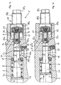
- the delivery unit generally designated 1, which constitutes a main component of the lubricating grease supply device according to the invention, has a delivery piston 3 which moves in a straight line back and forth in a delivery housing 2 and projects into a cavity 4 within the delivery housing 2 (cf.Fig. 1a, b ). Outside the cavity 4 (ie in Fig. 1a, b on the left side), the delivery piston 3 merges into a guide section 3a, to which (in the drawing to the left) an end plate 3b connects.
- the components 3a and 3b are - like a sealing washer 5 arranged in front of them - arranged in a larger chamber 6; this can be acted upon in a manner known per se via a supply line, not shown, with a pressurized fluid, with the result that an effective driving force acts on the delivery piston 3 in the delivery direction (arrow 7).
- the delivery piston is equipped with a mechanical reset in the form of a prestressed coil spring 8, which is supported at the same time on the end plate 3b and the sealing disk 5; the latter is supported on the delivery side on a shoulder 6a of the chamber 6. Under the action of the helical spring 8, the delivery piston 3 executes a suction movement opposite to the delivery direction (to the left in the drawing) if the chamber 6 is relieved of pressure.
- the cavity 4 is - seen in the conveying direction (arrow 7) - delimited by the end face 9a of an adjustment stop 9, which is essentially bush-like or sleeve-like and is attached to an adjusting bolt 10 on the side facing away from the end face 9a.
- This has (seen from left to right) an adjustment thread section 10a, a securing thread section 10b and a square section 10c, via which it can be rotated by means of a suitable tool.
- the securing thread section 10b which is essentially outside the conveyor housing, serves to fix the adjusting bolt 10 with respect to the conveyor housing by means of a locking nut (not shown) and to secure it against undesired displacement.
- the adjusting stop 9 can be axially displaced, as a result of which the position of the end face 9a with respect to the cavity 4 also changes.
- the adjustment stop points within its longitudinal bore 9b a locking element in the form of a spring-loaded Check valve 13, the closure ball 13a in the Resilient near the end face 9a on the adjustment stop is held in investment and shown in the Closed position the cavity 4 against the longitudinal bore 9b blocked.
- the conveyor housing 2 also has one in the cavity 4 opening supply line 14, the opening 14a in the cavity 4 - seen in the conveying direction (arrow 7) - in Area between the paragraph 6a and the end face 9a lies.
- a connection thread 14b can be used between the Supply line and a grease reservoir (cf. 6) a releasable connection getting produced.
- the feed line 14 is connected to a return line 15, which is equipped with a spring-loaded check valve 16. This normally assumes the closed position shown and, contrary to its resetting, can be transferred to the open position if the pressure level in the cavity 4 exceeds a predetermined limit value.
- the mouth 15a of the return line into the cavity is - seen in the direction of conveyance (arrow 7) - between the mouth 14a and the end face 9a of the adjustment stop.
- the aforementioned configuration and arrangement of the return line 15 divides the cavity 4 into a compression section V and an adjoining delivery section F (cf. FIG. 1b).
- the length of the compression section corresponds to the distance between the end regions of the orifices 14a and 15a, as seen in the direction of conveyance (arrow 7), that of the conveying section F approximately to the distance between the end region of the orifice 15a and the end face 9a.
- the check valve 13 is designed in such a way that the surface portion of the closure ball 13a facing the delivery piston 3 lies at least approximately in the plane of the end face 9a.
- the check valves 16 and 13 are matched in terms of their closing force in such a way that the check valve 16 serving as a return blocking element enters the valve at a lower pressure level Open position is transferred as the check valve 13 assigned to the delivery line 12.
- the closing force of the check valve 16 is dimensioned such that it always assumes the closed position when conveying a compressible medium; this has the consequence that the compressible medium sucked into the cavity 4 - after opening the check valve 13 as a result of a sufficiently high pressure level - can only be discharged to the outside via the longitudinal bore 9b and the delivery line 12, 12a.
- the opening of the check valve 13 can also be brought about mechanically, namely by the fact that the delivery piston 3 and / or the check valve 13 has a projection in the direction of the respectively opposite element 13 or 3.
- the delivery plunger 3 is supported by this - as soon as it has approached the adjustment stop 9 sufficiently far in the course of its delivery movement within the delivery section F - and mechanically transfers the check valve 13 to its open position when its delivery movement continues.
- FIGS. 1a, b works as follows: If air has been sucked from the supply line 14 into the cavity 4 by the suction movement of the delivery piston 3 (in the opposite direction to arrow 7), the subsequent movement of the delivery piston 3 in the delivery direction initially leads to the fact that the delivery piston head 3c closes the feed line opening 14a and then compresses the air volume enclosed in sections V and F - with the check valve 16 still closed - until the delivery piston 3 also reaches the end region of the opening 15a and thus the return line 15 has blocked against the cavity 4 (see. Fig. 1b).
- the air which now only fills the conveying section F is under an increased pressure which is sufficient to open the check valve 13 when the conveying piston 3 moves further in the conveying direction and to supply the air to the conveying line 12 via the bores 9b and 9c.
- This conveying process continues until the conveying piston head 3c comes to rest on the end face 9a and the conveying section F has (at least approximately) assumed the volume "zero". Accordingly, the delivery unit 1 is able to completely discharge any compressible medium that has been sucked in from the cavity 4.
- the check valve 13 can also be transferred mechanically into the open position in this case — with a suitable design of the delivery piston 3 and / or the check valve 13.
- the conveying section F (after the mouth 15a has been closed) contains the maximum volume that can be conveyed.
- the compression section in the case of grease delivery serves to discharge the grease proportion corresponding to its volume to the outside until the delivery piston has blocked the return line opening 15a in the course of its delivery movement.
- the return line together with the return blocking element is integrated in the delivery piston 3.
- the return line consists of a longitudinal bore 17 opening into the delivery piston head 3c, which is equipped with a spring-loaded check valve 18, and a transverse bore 19 connected to the longitudinal bore, which emerges from the circumferential surface of the piston on the side facing the feed line opening 14a.
- the length of the compression section V corresponds to the distance in the conveying direction between the end face of the delivery piston head 3c and the outer edge of the transverse bore 19 facing away from it in this direction.
- the length of the conveying section F in the conveying direction corresponds to the distance between the conveying piston head 3c and the end face 9a after the conveying piston 3 has reached a position in which the connection between the mouth 14a and the transverse bore 19 is interrupted, the delivery piston 3 blocking the feed line opening 14a.
- the alternative solution in question works when conveying a compressible medium or when conveying grease in a manner corresponding to the embodiment according to FIGS. 1a, b.
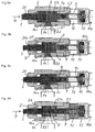
- the delivery piston 3 within the cavity 4 is equipped with an outer piston 20, which can move axially relative to the delivery piston 3 and whose range of motion is determined on the one hand by a shoulder 3d on the delivery piston and on the other hand by a boundary surface 21a which the compression section V merges into the conveyor section F having a smaller diameter.
- the boundary surface 21a represents the end face of the piston 3 and 20 of a bush-like insert 21 which is fastened to the conveyor housing 2 and into which the adjustment stop 9 projects.
- the length of the conveying section F corresponds - seen in the conveying direction (arrow 7) - to the distance between the boundary surface 21a and the end face 9a of the adjustment stop.
- the length of the compression section in the conveying direction is determined on the one hand by the position of the boundary surface 21a and on the other hand by the position which the end face 20a of the outer bulb assumes after it has just shut off the feed line mouth 14a against the cavity 4 in the course of its movement in the conveying direction.
- the drive-side end face 20b of the outer bulb - which projects into the chamber 6 in the starting position shown - can be acted upon by this, like the feed piston 3, with a fluid pressure medium and thereby displaced in the feed direction. Accordingly, the outer bulb 20 does not require a special, independent drive unit.
- the embodiment in question with a "two-part" piston arrangement has no special return line and return blocking element; their function is taken over by the outer bulb 20. If the delivery piston 3 moves in the suction direction after depressurizing the chamber 6 (counter to arrow 7) under the action of the helical spring 8, the outer piston 20 is carried along in this direction over the surface 3d until it has reached the starting position shown.
- the mode of operation of the embodiment in question (according to FIG. 3) when conveying a compressible medium (air conveyance) is explained in detail below with reference to FIGS. 4a to d.
- the releasably attached grease reservoir that cooperates with the delivery unit is designated by 22.
- the delivery piston can continue its delivery movement in the delivery section F.
- the associated increase in pressure within the conveying section has the result that the check valve 13 is transferred into its open position and the compressed air is fed through the adjusting stop 9 to the conveying line 12.
- the delivery piston continues its movement in the delivery direction until it comes to rest against the adjustment stop and the delivery section F has at least approximately assumed the volume "zero" (FIG. 4d).
- FIGS. 5a to d The mode of operation of the lubricating grease supply device according to FIG. 3 in the case of lubricating grease delivery can be seen from FIGS. 5a to d mentioned below:
- FIGS. 5a to d The mode of operation of the lubricating grease supply device according to FIG. 3 in the case of lubricating grease delivery can be seen from FIGS. 5a to d mentioned below:
- the pistons 3 and 20 are caused to move to the right in the direction of conveyance (arrow 7), with the result that first the feed line opening 14a - as can be seen in FIG. 5b - through the outer bulb 20 is closed. Accordingly, the grease is only in the part of the cavity 4, which is defined by the sections V and F. Since the compression force emanating from the outer piston 20 is set lower than the driving force acting on the delivery piston 3, the outer piston cannot continue its movement in the direction of delivery contrary to the action of the incompressible grease in contrast to the delivery piston 3; its further movement until it enters the conveying section F has the result that lubricating grease is displaced in the region of the compression section V, since the check valve 13 remains closed.
- the outer piston 20 is pushed back against the conveying direction (arrow 7) and thereby releases the feed line opening 14a, so that the displacement action of the feed piston 3 is returned to the feed line 14 and the lubricating grease reservoir 22 in accordance with the displacement effect of the feed piston 3 (cf. Fig. 5c).
- an additional device through which - triggered only by one available with grease delivery is sufficient high pressure level in the compression section V - a otherwise blocked return connection between the Compression section and the feed line 14 is made can be as long as the head of the delivery piston 3 its movement in the conveying direction (arrow 7) in the Compression section is located.
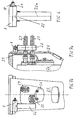
- Fig. 6 the lubricating grease supply device according to the invention consisting of the delivery unit 1 and the grease storage container 22 is shown schematically.
- the drawing also shows that the adjustment bolt 10 of the adjustment stop is clamped to the conveyor unit 1 by a lock nut 24 and is thereby secured against undesired rotation.
- the grease reservoir 22 preferably consists of a commercially available cartridge that can be connected to the feed line (see, for example, FIG. 3) by screwing in without the use of tools.
- the shell of the cartridge can be made of flexible material, which bends with increasing emptying in the direction of the longitudinal axis 22a and can thus indirectly identify the degree of emptying or remaining filling.
- the cartridge can also be used in the direction of the Longitudinal axis 22a movable floor and consist of transparent material, so that the location of the Cartridge bottom also the filling level of the cartridge displays.
- FIGS. 7a, b show an application example in which the grease supply device - comprising the delivery unit 1 and the grease storage container 22 (or the previously mentioned commercial cartridge) - is attached to the outer housing 25 of a hydraulic hammer 26.
- This is connected in a manner known per se via a pressure line 27 and a pressure-free return line 28 to a hydraulic unit (not shown).
- a line system 29 which connects the delivery unit 1 to the hydraulic hammer 26.
- This line system (with two separate individual lines, not shown) serves to supply the delivery unit 1 with drive energy on the one hand, and to couple the delivery line 12 (see, for example, FIGS. 1a, b) to the lubrication points of the hydraulic hammer 26 to be supplied with grease.
- the advantage achieved by the invention is that with simple means and reliably an undesirable compressible medium (normally air) from the area of the grease reservoir and the feed line Suction in the cavity of the conveyor unit can be eliminated can. This can cause malfunctions and damage the downstream of the grease feed device Avoid construction machinery that would otherwise result from this can that the grease feeder the associated lubrication points Grease supplied.
- an undesirable compressible medium normally air
- the invention also relates to a method for the supply of grease to construction machines, which is characterized in that a larger volume of a compressible or incompressible medium is first sucked into the cavity of a conveyor unit and - regardless of the compressibility of the medium - with each Delivery stroke of the associated delivery piston is a transport volume to the outside, which is smaller than the aforementioned suction volume.
- the method according to the invention is further configured such that part of the incompressible medium initially sucked into the cavity is returned to the outside of the cavity before the actual conveying process is initiated.
- the blocking element cooperating with the delivery line must be switched in such a way that it only opens after a possible return has taken place.
Landscapes
- Engineering & Computer Science (AREA)
- General Engineering & Computer Science (AREA)
- Mechanical Engineering (AREA)
- Percussive Tools And Related Accessories (AREA)
- Component Parts Of Construction Machinery (AREA)
- Compressor (AREA)
- Reciprocating Pumps (AREA)
- Details Of Reciprocating Pumps (AREA)
Description
In der Druckschrift EP-B1-0430024 ist eine Einrichtung der eingangs erwähnten Gattung beschrieben, mittels welcher der Meißel eines hydraulischen Schlagwerks automatisch geschmiert wird.
Die bekannte Einrichtung weist einen Vorratsbehälter auf, dessen Inhalt unter Einwirkung einer vorgespannten Druckfeder der Fördereinheit zugeführt wird. Diese ist zur Beseitigung etwa vorhandener Lufteinschlüsse mit einem besonderen Entlüftungsventil und im Bereich ihrer Förderleitung mit einem Rückschlagventil ausgestattet; letzteres bewirkt, daß die an den Hohlraum (Förderraum) der Fördereinheit angeschlossene Förderleitung lediglich in einer Richtung durchflossen werden kann.
Zur Sicherstellung ihrer einwandfreien Funktion muß die Fördereinheit nach jedem Wechsel des Vorratsbehälters mittels des Entlüfungsventils von dem dabei eingedrungenen Gas befreit werden; andernfalls besteht die Gefahr, daß die Fördereinheit über einen längeren Zeitraum kein Schmierfett transportiert.
Der Erfindungsgegenstand soll außerdem so ausgestaltet sein, daß die im wesentlichen aus dem Schmierfett-Vorratsbehälter und der Fördereinheit bestehende Zuführeinrichtung verhältnismäßig kleine Abmessungen aufweist und dementsprechend erforderlichenfalls in der Nähe der zu versorgenden Schmierstellen angeordnet werden kann.
Weiterhin soll es ggf. möglich sein, die Fördereinheit mit dem Fluid anzutreiben, welches ohnehin als Druckmittel für den Betrieb der zu schmierenden Baumaschine zur Verfügung steht.
Danach ist die gattungsgemäße Einrichtung derart weiter ausgestaltet, daß der in der Fördereinheit gebildete Hohlraum - in Richtung der Förderbewegung des Förderkolbens gesehen - hinter der Einmündung der Zuführleitung in ihn einen Verdichtungsabschnitt und daran anschließend einen Förderabschnitt aufweist. In dem Verdichtungsabschnitt wird nach dem Verschließen der Zuführleitung ein etwa angesaugtes kompressibles Medium (normalerweise Luft) bis auf das Volumen des Förderabschnitts verdichtet und anschließend - entgegen der Wirkung eines nachgiebig in der Schließstellung gehaltenen Sperrelements - in die Förderleitung gedrückt.
Die Schließkraft des mit der Förderleitung zusammenwirkenden Sperrelements ist dabei derart eingestellt, daß das Sperrelement frühestens dann öffnet, wenn der Kopf des Förderkolbens den Förderabschnitt erreicht und gegen den Verdichtungsabschnitt abgesperrt hat. Dementsprechend kann im Höchstfall die Menge des zwischen dem Förderkolben-Kopf und dem Verstellanschlag im Förderabschnitt eingeschlossenen Mediums in Richtung auf die Förderleitung ausgeschoben werden, nachdem das bereits erwähnte Sperrelement in seine Öffnungsstellung überführt worden ist.
Der Verdichtungsabschnitt innerhalb des Hohlraums ist also dadurch definiert, daß lediglich bei Schmierfett-Förderung eine Rückförderung in Richtung der Zuführleitung ausgelöst wird, so daß nur das im Förderabschnitt eingeschlossene Volumen die von der Fördereinheit pro Förderhub im Höchstfall zu liefernde Fördermenge darstellt.
Die Mindestlänge des Verdichtungsabschnitts in Richtung der Förderbewegung des Förderkolbens entspricht im Normalfall der Längserstreckung der Zuführleitungs-Einmündung in den Hohlraum. Durch besondere konstruktive Maßnahmen kann die Lage des Verdichtungsabschnitts bezüglich der erwähnten Einmündung ebenso wie seine Länge beeinflußt werden.
Der hier angesprochene mechanisch wirkende Öffnungsmechanismus ließe sich insbesondere dadurch verwirklichen, daß entweder der Förderkolben auf seiner dem Sperrelement zugewandten Seite und/oder das Sperrelement auf seiner dem Förderkolben zugewandten Seite einen Vorsprung aufweist, der im Laufe der Förderbewegung des Förderkolbens an dem jeweils anderen Teil (Sperrelement bzw. Förderkolben) zur Anlage kommt und dabei das Sperrelement entgegen seiner Rückstellung in Förderrichtung verschiebt.
Soweit das Sperrelement betroffen ist, kann dieses im einfachsten Fall zur Auslösung der mechanischen Verstellung derart ausgebildet sein, daß es in seiner Schließstellung entgegen der Förderrichtung über den Verstellanschlag hinaus in den Förderabschnitt hineinragt. Dementsprechend würde der Förderkolben im Laufe seiner Förderbewegung mit dem vorkragenden Sperrelement in Kontakt kommen und dieses in seine Öffnungsstellung verschieben, bevor der Förderkolben schließlich den Verstellanschlag berührt.
Eine derartige Ausgestaltung ist von Vorteil, falls die zu schmierende Baumaschine ohnehin für ihren Betrieb ein entsprechendes Druckmittel benötigt.
Falls die Höhe des Betriebsdrucks des fluiden Druckmittels zeitlich in geeigneter Weise verändert wird, kann die Arbeitsweise der Schmierfett-Zuführeinrichtung - wie mit der bereits erwähnten Druckschrift EP-B1-0430024 beschrieben - auch automatisiert werden.
Bei dieser Ausführungsform des Erfindungsgegenstandes ist eine in den Hohlraum einmündende Rückführleitung nach Überschreiten eines durch das Rückführ-Sperrelement vorgegebenen Drucks an die Zuführleitung angeschlossen, solange der sich in Förderrichtung bewegende Förderkolben innerhalb des Hohlraums eine geeignete Lage einnimmt.
Die in Rede stehende Ausführungsform arbeitet in dem hier angesprochenen Zusammenhang folgendermaßen: Nachdem der Förderkolben im Laufe seiner Bewegung in Förderrichtung die Zuführleitungseinmündung verschlossen hat, wird anschließend das in den Hohlraum angesaugte inkompressible Schmierfett - bei geöffnetem Zuführ-Sperrelement - solange in die Rückführleitung gepreßt, bis auch deren Einmündung in den Hohlraum durch den seine Förderbewegung fortsetzenden Förderkolben blockiert wird. Danach wird das nunmehr im Förderabschnitt eingeschlossene Schmierfett-Volumen bei sich öffnendem Sperrelement in die Förderleitung transportiert.
Die Länge des Verdichtungsabschnitts in Förderrichtung entspricht dabei dem Abstand zwischen dem Endbereich der Zuführleitungseinmündung und dem Endbereich der Einmündung der Rückführleitung in den Hohlraum; der letztgenannte Endbereich bildet gleichzeitig den Anfangsbereich des Förderabschnitts, welcher in Förderrichtung durch den Verstellanschlag begrenzt ist.
Die Rückführleitung kann dabei aus einer in den Förderkolben-Kopf einmündenden Längsbohrung und einer mit dieser verbundenen Querbohrung bestehen, die auf der der Zuführleitungseinmündung zugewandten Seite an der Kolben-Umfangsfläche austritt (Anspruch 9). Dementsprechend ergibt sich die Länge des Verdichtungsabschnitts in Förderrichtung aus der zugehörigen Längserstreckung der Zuführleitungseinmündung in den Hohlraum zuzüglich der Länge der Querbohrung an der der Zuführleitungseinmündung zugewandten Kolben-Umfangsfläche.
Sobald die Querbohrung bei Schmierfett-Förderung des Förderkolbens den Anfangsbereich der Zuführleitungseinmündung erreicht hat, nimmt das Rückführ-Sperrelement die Öffnungsstellung ein mit der Folge, daß durch die Längsbohrung und die Querbohrung Schmierfett in die Zuführleitung zurückgeführt wird. Dieser Vorgang läuft solange ab, bis im Laufe der Weiterbewegung des Förderkolbens in Förderrichtung der Endbereich der Querbohrung mit dem Endbereich der Zuführleitungseinmündung zusammenfällt und dann die Verbindung zwischen der Querbohrung und der Zuführleitungseinmündung unterbrochen wird. Die zuletzt angesprochene Stellung des Förderkolbens innerhalb des Hohlraums legt gleichzeitig den Anfangsbereich des Förderabschnitts - und damit dessen Länge in Förderrichtung - fest.
Die in Rede stehende Auslegung des Antriebs hat zur Folge, daß sich zunächst beide Kolben - entgegen dem vom angesaugten kompressiblen Medium ausgehenden Widerstand - solange in Förderrichtung weiterbewegen, bis der Außenkolben an der Begrenzungsfläche zur Anlage gekommen ist und das kompressible Medium in entsprechend verdichtetem Zustand nur noch den Förderabschnitt ausfüllt. Dieses wird anschließend in die Förderleitung überführt, sobald aufgrund der Weiterbewegung des Förderkolbens in Förderrichtung im Förderabschnitt das die Förderleitung blockierende Sperrelement in seine Öffnungsstellung überführt worden ist, und zwar unter Einwirkung eines ausreichend hohen Druckniveaus oder - wie zuvor erwähnt (vgl. Anspruch 4) - auf mechanischem Weg.
Im Falle der Schmierfett-Förderung bewegen sich beide Kolben solange gemeinsam in Förderrichtung, bis der Außenkolben die Zuführleitungseinmündung blockiert hat. Da sich der Förderkolben aufgrund der an ihm angreifenden größeren Antriebskraft anschließend in Förderrichtung weiterbewegt, wird der Außenkolben unter Einwirkung des inkompressiblen Schmierfetts entgegen der Förderrichtung zurückgeschoben, wodurch eine Rückführ-Verbindung mit der Zuführleitung hergestellt wird. Diese Rückführ-Verbindung bleibt solange bestehen, bis der Förderkolben im Laufe der weiteren Bewegung in Förderrichtung den Anfangsbereich des Förderabschnitts erreicht und diesen gegen den vorausgehenden Verdichtungsabschnitt verschließt. Das nunmehr im Förderabschnitt befindliche Schmierfett wird anschließend - nach Öffnen des Sperrelements - in die Förderleitung überführt, bis der Förderkolben seine Endlage am Verstellanschlag eingenommen hat.
Bei dieser Ausgestaltung ist das betreffende Sperrelement im Bereich des Verstellanschlags also derart ausgebildet und an diesen angepaßt, daß zwischen der den Förderabschnitt begrenzenden Stirnfläche des Verstellanschlags und dem Sperrelement selbst möglichst keine Ausnehmungen, Aussparungen, Lücken oder dergleichen vorhanden sind, falls das Sperrelement seine Schließstellung einnimmt.
Es zeigen:
- Fig. 1a, b
- einen Teilschnitt durch die Fördereinheit der erfindungsgemäßen Schmierfett-Zuführeinrichtung in unterschiedlichen Betriebszuständen, wobei die Rückführleitung außerhalb des Förderkolbens angeordnet ist,
- Fig. 2a, b
- einen Teilschnitt durch die Fördereinheit der erfindungsgemäßen Schmierfett-Zuführeinrichtung in verschiedenen Betriebszuständen, wobei die Rückführleitung im Förderkolben angeordnet ist,
- Fig. 3
- einen Teilschnitt durch eine Fördereinheit, deren Förderkolben zusätzlich mit einem Außenkolben ausgestattet ist,
- Fig. 4a bis d
- verschiedene Betriebszustände der Fördereinheit gemäß Fig. 3 bei Luftförderung,
- Fig. 5a bis d
- verschiedene Betriebszustände der Fördereinheit gemäß Fig. 3 bei Schmierfett-Förderung,
- Fig. 6
- eine Ansicht einer Fördereinheit mit zugehörigem Schmierfett-Vorratsbehälter und
- Fig. 7a, b
- einen Teilschnitt bzw. eine Teilansicht einer Anordnung, bei welcher die erfindungsgemäße Schmierfett-Zuführeinrichtung an dem Außengehäuse eines Hydraulikhammers befestigt ist.
In dem dargestellten Ausführungsbeispiel ist der Förderkolben mit einer mechanischen Rückstellung in Gestalt einer vorgespannten Schraubenfeder 8 ausgestattet, die sich gleichzeitig an der Abschlußplatte 3b und der Dichtscheibe 5 abstützt; letztere stützt sich förderseitig an einem Absatz 6a der Kammer 6 ab. Unter Einwirkung der Schraubenfeder 8 führt der Förderkolben 3 eine der Förderrichtung entgegengesetzte Ansaugbewegung (in der Zeichnung nach links) aus, falls die Kammer 6 druckentlastet wird.
Der Verstellgewindeabschnitt 10a - in dem auch der Verstellanschlag 9 ruht - greift innerhalb des Fördergehäuses 2 in ein Innengewinde 11 ein, welches einen Teil der Wandung einer Förderleitung 12 bildet. Der im wesentlichen außerhalb des Fördergehäuses liegende Sicherungsgewindeabschnitt 10b dient dazu, den Verstellbolzen 10 mittels einer nicht dargestellten Sicherungsmutter bezüglich des Fördergehäuses zu fixieren und gegen eine unerwünschte Verschiebung zu sichern.
Durch Drehen des Verstellbolzens 10 bezüglich des Fördergehäuses läßt sich der Verstellanschlag 9 axial verschieben, wodurch sich die Lage auch der Stirnfläche 9a bezüglich des Hohlraums 4 verändert.
Die Einmündung 15a der Rückführleitung in den Hohlraum befindet sich - in Förderrichtung (Pfeil 7) gesehen - zwischen der Einmündung 14a und der Stirnfläche 9a des Verstellanschlags.
Durch die erwähnte Ausgestaltung und Anordnung der Rückführleitung 15 wird der Hohlraum 4 in einen Verdichtungsabschnitt V und einen sich daran anschließenden Förderabschnitt F unterteilt (vgl. dazu Fig. 1b).
Die Länge des Verdichtungsabschnitts entspricht dabei - jeweils in Förderrichtung (Pfeil 7) gesehen - in etwa dem Abstand zwischen den Endbereichen der Einmündungen 14a und 15a, diejenige des Förderabschnitts F in etwa dem Abstand zwischen dem Endbereich der Einmündung 15a und der Stirnfläche 9a.
Ausweislich der Darstellung ist das Rückschlagventil 13 derart ausgebildet, daß der dem Förderkolben 3 zugewandte Oberflächenanteil der Verschlußkugel 13a zumindest annähernd in der Ebene der Stirnfläche 9a liegt.
Darüber hinaus ist die Schließkraft des Rückschlagventils 16 derart bemessen, daß es bei Förderung eines kompressiblen Mediums stets die Schließstellung einnimmt; dies hat zur Folge, daß das etwa in den Hohlraum 4 angesaugte kompressible Medium - nach Öffnen des Rückschlagventils 13 in Folge eines ausreichend hohen Druckniveaus - ausschließlich über die Längsbohrung 9b und die Förderleitung 12, 12a nach außen abgeführt werden kann. Statt dessen kann die Öffnung des Rückschlagventils 13 auch auf mechanischem Weg herbeigeführt werden, und zwar dadurch, daß der Förderkolben 3 und/oder das Rückschlagventil 13 in Richtung auf das jeweils gegenüberliegende Element 13 bzw. 3 einen Vorsprung aufweist. Über diesen stützt sich der Förderkolben 3 - sobald er sich im Laufe seiner Förderbewegung innerhalb des Förderabschnitts F dem Verstellanschlag 9 ausreichend weit angenähert hat - ab und überführt bei Fortsetzung seiner Förderbewegung das Rückschlagventil 13 mechanisch in seine Öffnungsstellung.
Die nunmehr nur noch den Förderabschnitt F ausfüllende Luft steht zu diesem Zeitpunkt unter einem erhöhten Druck, der dazu ausreicht, das Rückschlagventil 13 bei der Weiterbewegung des Förderkolbens 3 in Förderrichtung zu öffnen und die Luft über die Bohrungen 9b und 9c der Förderleitung 12 zuzuführen. Dieser Fördervorgang läuft solange ab, bis der Förderkolbenkopf 3c an der Stirnfläche 9a zur Anlage gekommen ist und somit der Förderabschnitt F (zumindest annähernd) das Volumen "Null" angenommen hat. Dementsprechend ist die Fördereinheit 1 in der Lage, ein etwa angesaugtes kompressibles Medium vollständig aus dem Hohlraum 4 abzuführen.
Wie bereits zuvor erläutert worden ist, kann auch in diesem Fall das Rückschlagventil 13 - bei geeigneter Ausbildung des Förderkolbens 3 und/oder des Rückschlagventils 13 - mechanisch in die Öffnungsstellung überführt werden.
Bei der Förderung eines kompressiblen Mediums wird dieses beim Durchfahren des Verdichtungsabschnitts lediglich komprimiert; im Gegensatz dazu dient der Verdichtungsabschnitt bei Schmierfett-Förderung dazu, den seinem Volumen entsprechenden Schmierfettanteil nach außen abzuführen, bis der Förderkolben im Laufe seiner Förderbewegung die Rückführleitungseinmündung 15a blockiert hat.
Die Rückführleitung besteht dabei aus einer in den Förderkolben-Kopf 3c einmündenden Längsbohrung 17, die mit einem federbeaufschlagten Rückschlagventil 18 ausgestattet ist, und einer mit der Längsbohrung verbundenen Querbohrung 19, welche auf der der Zuführleitungseinmündung 14a zugewandten Seite aus der Kolbenumfangsfläche austritt.
Die Länge des Verdichtungsabschnitts V entspricht dabei dem Abstand in Förderrichtung zwischen der Stirnfläche des Förderkolben-Kopfes 3c und der von diesem abgewandten Außenkante der Querbohrung 19 in dieser Richtung.
Im übrigen arbeitet die in Rede stehende Alternativlösung bei Förderung eines kompressiblen Mediums bzw. bei Schmierfett-Förderung in entsprechender Weise wie die Ausführungsform gemäß Fig. 1a, b.
Die Begrenzungsfläche 21a stellt dabei die den Kolben 3 und 20 zugewandte Stirnfläche eines buchsenartigen Einsatzteils 21 dar, welches am Fördergehäuse 2 befestigt ist und in welches der Verstellanschlag 9 hineinragt.
Die Länge des Förderabschnitts F entspricht - in Förderrichtung (Pfeil 7) gesehen - dem Abstand zwischen der Begrenzungsfläche 21a und der Stirnfläche 9a des Verstellanschlags.
Die Länge des Verdichtungsabschnitts in Förderrichtung ist einerseits festgelegt durch die Lage der Begrenzungsfläche 21a und andererseits durch die Lage, welche die Stirnfläche 20a des Außenkolbens einnimmt, nachdem dieser im Laufe seiner Bewegung in Förderrichtung gerade die Zuführleitungseinmündung 14a gegen den Hohlraum 4 abgesperrt hat.
Die antriebsseitige Stirnfläche 20b des Außenkolbens - welche in der gezeigten Ausgangsstellung in die Kammer 6 hineinragt - kann über diese ebenso wie der Förderkolben 3 mit einem fluiden Druckmittel beaufschlagt und dadurch in Förderrichtung verschoben werden. Dementsprechend benötigt der Außenkolben 20 keine besondere, eigenständige Antriebseinheit.
Falls sich der Förderkolben 3 nach Druckentlastung der Kammer 6 (entgegen Pfeil 7) unter Einwirkung der Schraubenfeder 8 in Ansaugrichtung bewegt, wird der Außenkolben 20 über die Fläche 3d in dieser Richtung mitgeführt, bis er die gezeigte Ausgangsstellung erreicht hat.
Der mit der Fördereinheit zusammenwirkende, lösbar befestigte Schmierfett-Vorratsbehälter ist dabei mit 22 bezeichnet.
Da beide Kolben 3 und 20 zunächst ihre Bewegung in Förderrichtung fortsetzen, wird die eingeschlossene Luft währenddessen verdichtet, wobei der Außenkolben 20 schließlich an der Begrenzungsfläche 21a zur Anlage kommt und der Förderkolben 3 den Förderabschnitt F erreicht. Dementsprechend nimmt die verdichtete Luft nur noch das dem Förderabschnitt F entsprechende Volumen ein (Fig. 4c).
Die zuvor skizzierten Abläufe setzen also voraus, daß die den Außenkolben 20 antreibende Verdichtungskraft derart bemessen ist, daß der Außenkolben - entgegen dem von der Luft ausgehenden Widerstand - an der Begrenzungsfläche 21a zur Anlage kommt.
Der Förderkolben setzt dabei seine Bewegung in Förderrichtung solange fort, bis er am Verstellanschlag zur Anlage gekommen ist und der Förderabschnitt F zumindest annähernd das Volumen "Null" angenommen hat (Fig. 4d).
Im Laufe der in Fig. 5a dargestellten Ansaugphase ist durch Bewegung der Kolben 3 und 20 aus dem Schmierfett-Vorratsbehälter 22 durch die Zuführleitung 14 Schmierfett in den Hohlraum 4 angesaugt worden, wobei das Rückschlagventil 13 im Verstellanschlag 9 die Schließstellung einnimmt.
Die Eintrittsbewegung des Schmierfetts in den Hohlraum 4 ist durch einen Pfeil 23 angedeutet.
Da die vom Außenkolben 20 ausgehende Verdichtungskraft kleiner eingestellt ist als die am Förderkolben 3 angreifende Antriebskraft, kann der Außenkolben seine Bewegung in Förderrichtung entgegen der Wirkung des inkompressiblen Schmierfetts im Gegensatz zum Förderkolben 3 nicht fortsetzen; dessen Weiterbewegung bis zum Eintritt in den Förderabschnitt F hat zur Folge, daß im Bereich des Verdichtungsabschnitts V Schmierfett verdrängt wird, da das Rückschlagventil 13 weiterhin geschlossen bleibt. Dementsprechend wird der Außenkolben 20 - entgegen der Förderrichtung (Pfeil 7) - zurückgeschoben und gibt dabei die Zuführleitungseinmündung 14a frei, so daß der Verdrängungswirkung des Förderkolbens 3 entsprechend Schmierfett in Richtung auf die Zuführleitung 14 und den Schmierfett-Vorratsbehälter 22 zurückgeführt wird (vgl. dazu Fig. 5c).
Die Weiterbewegung des Förderkolbens 3 nach Blockieren des Förderabschnitts F gegen den Verdichtungsabschnitt V hat zur Folge, daß im Bereich des Verdichtungsabschnitts kein Verdrängungsvorgang mehr stattfindet. Dies führt dazu, daß der Außenkolben 20 schließlich erneut die in Fig. 5d angedeutete Lage einnimmt, in welcher die Zuführleitungseinmündung 14a zumindest annähernd durch ihn gegen den Verdichtungsabschnitt V abgesperrt ist.
Die Zeichnung läßt auch erkennen, daß der Verstellbolzen 10 des Verstellanschlags durch eine Sicherungsmutter 24 mit der Fördereinheit 1 verspannt und dadurch gegen eine unerwünschte Drehung gesichert ist.
Der Mantel der Kartusche kann aus flexiblem Material bestehen, welches sich mit zunehmender Entleerung in Richtung auf die Längsachse 22a krümmt und dadurch mittelbar den Entleerungs- bzw. Restfüllgrad erkennen läßt.
Dieses Leitungssystem (mit zwei getrennten, nicht dargestellten Einzelleitungen) dient dazu, einerseits die Fördereinheit 1 mit Antriebsenergie zu versorgen und andererseits die Förderleitung 12 (vgl. dazu beispielsweise Fig. 1a, b) an die mit Schmierfett zu versorgenden Schmierstellen des Hydraulikhammers 26 anzukoppeln.
Zu diesem Zweck muß das mit der Förderleitung zusammenwirkende Sperrelement derart geschaltet werden, daß es erst öffnet, nachdem eine etwaige Rückförderung stattgefunden hat.
Claims (13)
- Schmierfett-Zuführeinrichtung für Baumaschinen, insbesondere hydraulisch betriebene Schlagwerke und Abbruchzangen, mit einer an einen Schmierfett-Vorratsbehälter (22) angeschlossenen Fördereinheit (1), die in einem Hohlraum (4) einen geradlinig hin und her bewegten Förderkolben (3), eine in den Hohlraum (4) einmündende und mit dem Schmierfett-Vorratsbehälter (22) verbundene Zuführleitung (14), eine in den Hohlraum (4) einmündende Förderleitung (12) mit einem nachgiebig in der Schließstellung gehaltenen Sperrelement (13) und einem Verstellanschlag (9) aufweist, welcher den Hub des Förderkolbens (3) in Richtung seiner Förderbewegung (Pfeil 7) begrenzt, wobei die Einmündung (14a) der Zuführleitung (14) in den Hohlraum (4) - in Richtung der Förderbewegung (Pfeil 7) gesehen - vor derjenigen der Förderleitung (12) angeordnet und zumindest zeitweilig gegen den Hohlraum (4) abgesperrt ist, falls sich der Förderkolben (3) in Förderrichtung über sie hinaus verschiebt,
gekennzeichnet durch folgende Merkmale:der Hohlraum (4) weist - in Richtung der Förderbewegung (Pfeil 7) gesehen - hinter der Einmündung (14a) der zuführleitung (14) in ihn einen Verdichtungsabschnitt (V) und daran anschließend einen Förderabschnitt (F) auf;über eine Zusatz-Einrichtung (15, 16; 17 bis 19; 20) wird - ausgelöst durch ein nur bei Schmierfett-Förderung vorhandenes, ausreichend hohes Druckniveau im Verdichtungsabschnitt (V) - eine ansonsten blockierte, von dem Verdichtungsabschnitt (V) in die Zuführleitung (14) mündende Rückführ-Verbindung hergestellt, solange sich der Kopf des Förderkolbens (3) bei seiner Bewegung in Förderrichtung in dem Verdichtungsabschnitt (V) befindet; unddie Schließkraft des Sperrelements (13) ist derart eingestellt, daß es frühestens dann öffnet, wenn der Kopf des Förderkolbens (3) den Förderabschnitt (F) erreicht und gegen den Verdichtungsabschnitt (V) abgesperrt hat. - Vorrichtung nach Anspruch 1, dadurch gekennzeichnet, daß die Einmündung (9b) der Förderleitung (12) in den Förderabschnitt (F) in dem Verstellanschlag (9) angeordnet ist.
- Vorrichtung nach zumindest einem der vorhergehenden Ansprüche, dadurch gekennzeichnet, daß das Sperrelement (13) in der Schließstellung einen Teil der Stirnfläche (9a) des Verstellanschlags (9) bildet, welche den Förderabschnitt (F) begrenzt.
- Vorrichtung nach zumindest einem der vorhergehenden Ansprüche, dadurch gekennzeichnet, daß das Sperrelement (13) mechanisch geöffnet wird, sobald der Kopf (3c) des Förderkolbens (3) bei seiner Bewegung in Förderrichtung (Pfeil 7) sich im Förderabschnitt (F) in der Nähe des Verstellanschlags (9) befindet.
- Vorrichtung nach zumindest einem der vorhergehenden Ansprüche, dadurch gekennzeichnet, daß der Förderkolben (3) mittels eines außerhalb des Hohlraums (4) angreifenden fluiden Druckmittels in Förderrichtung (Pfeil 7) angetrieben werden kann und eine in Ansaugrichtung wirksame mechanische Rückstellung (8) aufweist.
- Vorrichtung nach zumindest einem der vorhergehenden Ansprüche, dadurch gekennzeichnet, daß die Zusatz-Einrichtung aus einem nachgiebig in der Schließstellung gehaltenen Rückführ-Sperrelement (16 bzw. 18) besteht, über welches eine in den Hohlraum (4) einmündende Rückführleitung (15 bzw. 17, 19) zumindest zeitweilig an die Zuführleitung (14) angeschlossen ist.
- Vorrichtung nach zumindest einem der vorhergehenden Ansprüche, dadurch gekennzeichnet, daß die Rückführleitung (15) außerhalb des Förderkolbens (3) angeordnet ist und ihre Einmündung (15a) in den Hohlraum (4) das Ende des Verdichtungsabschnitts (V) in Förderrichtung (Pfeil 7) festlegt.
- Vorrichtung nach zumindest einem der Ansprüche 1 bis 6, dadurch gekennzeichnet, daß die Rückführleitung (17, 19) nebst Rückführ-Sperrelement (18) in den Förderkolben (3) integriert ist.
- Vorrichtung nach Anspruch 8, dadurch gekennzeichnet, daß die Rückführleitung aus einer in den Förderkolben-Kopf einmündenden Längsbohrung (17) und einer mit dieser verbundenen Querbohrung (19) besteht, die auf der der Zuführleitungseinmündung (14a) zugewandten Seite an der Kolben-Umfangsfläche austritt.
- Vorrichtung nach zumindest einem der vorhergehenden Ansprüche 1 bis 5, dadurch gekennzeichnet, daß der Förderkolben (3) innerhalb des Hohlraums (4) einen Außenkolben (20) aufweist, der sich relativ zum Förderkolben axial bewegen kann und dessen Bewegungsspielraum einerseits durch ein Halteelement (3d) am Förderkolben (3) und andererseits durch eine Begrenzungsfläche (21a) festgelegt ist, an welcher der Verdichtungsabschnitt (v) in den einen kleineren Durchmesser aufweisenden Förderabschnitt (F) übergeht, wobei die am Außenkolben (20) in Förderrichtung (Pfeil 7) angreifende Verdichtungskraft kleiner als die den Förderkolben (3) in dieser Richtung bewegende Antriebskraft und derart eingestellt ist, daß der Außenkolben (20) - entgegen der Wirkung des in den Hohlraum (4) eingetretenen kompressiblen Mediums - seine Endlage an der Begrenzungsfläche (21a) einnehmen kann.
- Vorrichtung nach Anspruch 10, dadurch gekennzeichnet, daß der Außenkolben (20) außerhalb des Hohlraums (4) mit dem fluiden Druckmittel beaufschlagt ist, welches auch den Förderkolben (3) antreibt.
- Vorrichtung nach zumindest einem der vorhergehenden Ansprüche, dadurch gekennzeichnet, daß das Sperrelement (13) bzw. Rückführ-Sperrelement (16 bzw. 18) als federbeaufschlagtes Rückschlagventil ausgebildet ist.
- Vorrichtung nach zumindest einem der vorhergehenden Ansprüche, dadurch gekennzeichnet, daß das Sperrelement (13) unmittelbar einen Teil der Wandung des Förderabschnitts (F) vor der Förderleitung (12) bildet derart, daß der Förderabschnitt (F) zumindest annähernd das Volumen "Null" aufweist, falls der Förderkolben (3) am Verstellanschlag (9) anliegt.
Applications Claiming Priority (2)
| Application Number | Priority Date | Filing Date | Title |
|---|---|---|---|
| DE19704958 | 1997-02-10 | ||
| DE19704958A DE19704958C2 (de) | 1997-02-10 | 1997-02-10 | Schmierfett-Zuführeinrichtung für Baumaschinen, insbesondere hydraulisch betriebene Schlagwerke und Abbruchzangen |
Publications (2)
| Publication Number | Publication Date |
|---|---|
| EP0857910A1 EP0857910A1 (de) | 1998-08-12 |
| EP0857910B1 true EP0857910B1 (de) | 2003-07-09 |
Family
ID=7819800
Family Applications (1)
| Application Number | Title | Priority Date | Filing Date |
|---|---|---|---|
| EP98101681A Expired - Lifetime EP0857910B1 (de) | 1997-02-10 | 1998-01-31 | Schmierfett-Zuführeinrichtung für Baumaschinen, insbesondere hydraulisch betriebene Schlagwerke und Abbruchzangen |
Country Status (5)
| Country | Link |
|---|---|
| US (1) | US6145625A (de) |
| EP (1) | EP0857910B1 (de) |
| JP (1) | JP4170430B2 (de) |
| DE (2) | DE19704958C2 (de) |
| ES (1) | ES2198018T3 (de) |
Families Citing this family (41)
| Publication number | Priority date | Publication date | Assignee | Title |
|---|---|---|---|---|
| GB2358441A (en) * | 2000-01-18 | 2001-07-25 | Jo Bee Liu | Axle bearing lubricating device |
| US6276492B1 (en) * | 2000-03-07 | 2001-08-21 | Westinghouse Air Brake Company | Push rod activated grease nozzle |
| FR2831941B1 (fr) | 2001-11-08 | 2004-02-27 | Airbus France | Dispositif de lubrification d'un palier a rotule |
| US8047302B2 (en) * | 2001-12-21 | 2011-11-01 | Wacker Neuson Produktion GmbH & Co. KG | Drilling and/or striking hammer with a lubricating device |
| DE10163278A1 (de) * | 2001-12-21 | 2003-07-10 | Wacker Construction Equipment | Bohr- und/oder Schlaghammer mit einer Schmiervorrichtung |
| UA56088C2 (en) * | 2002-11-22 | 2005-03-15 | Close Corp Res And Production | Mobile pulse feeder |
| DE20309553U1 (de) * | 2003-06-21 | 2003-09-11 | Lincoln GmbH & Co. KG, 69190 Walldorf | Verteilerelement für Schmieranlagen |
| EP1717507B1 (de) * | 2005-04-27 | 2010-07-14 | Caterpillar Inc. | Schmierungsvorrichtung für hydraulisches oder pneumatisches Werkzeug |
| US20070137934A1 (en) * | 2005-11-07 | 2007-06-21 | The Boeing Company | Portable tool lubrication system |
| JP2007253311A (ja) * | 2006-03-27 | 2007-10-04 | Nippon Pneumatic Mfg Co Ltd | 潤滑剤供給装置 |
| DE102006026274A1 (de) | 2006-06-02 | 2007-12-06 | Willy Vogel Ag | Selbsttätige Schmierpumpe mit doppelt wirkendem Antriebskolben |
| US8986253B2 (en) | 2008-01-25 | 2015-03-24 | Tandem Diabetes Care, Inc. | Two chamber pumps and related methods |
| US8408421B2 (en) | 2008-09-16 | 2013-04-02 | Tandem Diabetes Care, Inc. | Flow regulating stopcocks and related methods |
| CA2737461A1 (en) | 2008-09-19 | 2010-03-25 | Tandem Diabetes Care, Inc. | Solute concentration measurement device and related methods |
| EP2724739B1 (de) | 2009-07-30 | 2015-07-01 | Tandem Diabetes Care, Inc. | Tragbares Infusionspumpensystem |
| CN102022611A (zh) * | 2009-09-23 | 2011-04-20 | 贺勍 | 新型润滑泵及防柱塞和缸体磨损的体积占有排脂法 |
| WO2012024503A1 (en) | 2010-08-19 | 2012-02-23 | Caterpillar Inc. | Lubrication system for a breaking tool |
| US9010493B2 (en) * | 2012-03-13 | 2015-04-21 | Caterpillar Inc. | Lubrication arrangement |
| US20130240568A1 (en) * | 2012-03-19 | 2013-09-19 | Yu-Sheng Shiau | Molten wax pumping device and molten wax dispenser using same |
| US9180242B2 (en) | 2012-05-17 | 2015-11-10 | Tandem Diabetes Care, Inc. | Methods and devices for multiple fluid transfer |
| CN102734623A (zh) * | 2012-06-26 | 2012-10-17 | 三一重型装备有限公司 | 自动润滑系统及工程机械 |
| CN103148331B (zh) * | 2013-02-22 | 2015-05-06 | 张付成 | 一种黄油加注枪 |
| US9173998B2 (en) | 2013-03-14 | 2015-11-03 | Tandem Diabetes Care, Inc. | System and method for detecting occlusions in an infusion pump |
| US9217341B2 (en) | 2013-08-15 | 2015-12-22 | Caterpillar Inc. | Lubrication system for tool |
| CN104006282A (zh) * | 2014-05-27 | 2014-08-27 | 郑州奥特科技有限公司 | 一种双路控制吸脂器及废脂回收装置 |
| NL2013166B1 (en) * | 2014-07-10 | 2016-09-21 | Groeneveld Transp Efficiency B V | Pump element, pump and lubrication system. |
| US9643310B2 (en) * | 2014-08-12 | 2017-05-09 | Caterpillar Inc. | Automatic lubrication system with detune |
| CN104864252A (zh) * | 2015-04-15 | 2015-08-26 | 中山市鸿程科研技术服务有限公司 | 一种引风机电机润滑装置 |
| US10335939B2 (en) * | 2016-10-12 | 2019-07-02 | Caterpillar Inc. | Lubrication system for hydraulic hammer |
| US10480712B2 (en) * | 2016-11-15 | 2019-11-19 | Caterpillar Inc. | System and method for preventing air in lubricant supply lines |
| US10682748B2 (en) * | 2017-12-19 | 2020-06-16 | Caterpillar Inc. | Auto-lubrication system for a work tool |
| KR102103906B1 (ko) * | 2018-05-18 | 2020-05-29 | 주식회사수산중공업 | 윤활유 자동공급구조가 구비된 유압 브레이커 |
| KR102093123B1 (ko) * | 2019-04-03 | 2020-03-25 | 유제국 | 크라샤의 윤활제 공급장치 |
| WO2022061459A1 (en) * | 2020-09-24 | 2022-03-31 | Lubecore International Inc. | Lubricant delivery apparatus |
| CN112377090B (zh) * | 2020-10-27 | 2022-05-10 | 中煤科工集团西安研究院有限公司 | 一种喷雾润滑钻杆 |
| US11983498B2 (en) * | 2021-03-18 | 2024-05-14 | Augmented Intelligence Technologies, Inc. | System and methods for language processing of document sequences using a neural network |
| AU2024257296A1 (en) | 2023-04-18 | 2025-10-09 | Corsaer Holding B.V. | An oil recovery system |
| NL2034602B1 (en) | 2023-04-18 | 2024-10-28 | Corsaer Holding B V | A pump system |
| NL2034603B1 (en) | 2023-04-18 | 2024-10-28 | Corsaer Holding B V | An oil recovery system |
| DE102024202732A1 (de) * | 2024-03-22 | 2025-09-25 | Skf Lubrication Systems Germany Gmbh | Pumpenelement für Schmierstoff |
| CN120312749B (zh) * | 2025-06-17 | 2025-09-02 | 洛阳制动新能源科技有限公司 | 一种油气混合润滑高效冷却滑动轴承及其冷却方法 |
Family Cites Families (15)
| Publication number | Priority date | Publication date | Assignee | Title |
|---|---|---|---|---|
| DE608034C (de) * | 1932-03-12 | 1935-01-14 | Limon Fluhme & Co De | Kolbenschmierpumpe mit einer mittels eines Rueckschlagventils gesteuerten Ansaugoeffnung, die oberhalb des Druckraumes liegt |
| DE866746C (de) * | 1944-02-10 | 1953-02-12 | Bosch Gmbh Robert | Schmierpumpe |
| US3291350A (en) * | 1963-11-05 | 1966-12-13 | Jerry P Malec | Fluid pump |
| US3599753A (en) * | 1969-07-14 | 1971-08-17 | Warren J Walsh | Conveyor roller lubricating device |
| DE2319249C3 (de) * | 1973-04-16 | 1978-06-08 | Joseph Voegele Ag, 6800 Mannheim | Pumpe zur Förderung von Fett in Schmieranlagen |
| FI126974A7 (de) * | 1974-04-25 | 1975-10-26 | Tampella Oy Ab | |
| DK149739C (da) * | 1983-11-25 | 1987-02-16 | Westergaard Knud Erik | Haejtryksrenser med trykstyret omlaebsventil |
| DE3512020C2 (de) * | 1985-04-02 | 1987-01-22 | Bielomatik Leuze Gmbh + Co, 7442 Neuffen | Förder-Pumpe für höher viskose Medien |
| US4739854A (en) * | 1987-01-20 | 1988-04-26 | Hein-Werner Corporation | Hydraulic fluid pump assembly for use in truck cab tilt apparatus |
| JPS63170578U (de) * | 1987-04-28 | 1988-11-07 | ||
| US4738595A (en) * | 1987-05-22 | 1988-04-19 | Allied Corporation | Hydraulic pump with integrated sump and accumulator |
| DE3939785A1 (de) * | 1989-12-01 | 1991-06-06 | Krupp Maschinentechnik | Automatische schmiereinrichtung fuer den meissel eines hydraulischen schlagwerks |
| US5449051A (en) * | 1993-12-16 | 1995-09-12 | Liao; Pen-Huai | Pneumatic oil lubricator |
| US5570868A (en) * | 1995-06-02 | 1996-11-05 | L & M Manufacturing, Inc. | Lubricating valve for a pump |
| DE29614316U1 (de) * | 1996-08-20 | 1996-10-17 | Gotec S.A., Sion | Kolbenpumpe, insbesondere Schwingkolbenpumpe, mit Ansaughilfe |
-
1997
- 1997-02-10 DE DE19704958A patent/DE19704958C2/de not_active Expired - Fee Related
-
1998
- 1998-01-31 ES ES98101681T patent/ES2198018T3/es not_active Expired - Lifetime
- 1998-01-31 EP EP98101681A patent/EP0857910B1/de not_active Expired - Lifetime
- 1998-01-31 DE DE59808936T patent/DE59808936D1/de not_active Expired - Lifetime
- 1998-02-10 US US09/021,366 patent/US6145625A/en not_active Expired - Lifetime
- 1998-02-10 JP JP02820298A patent/JP4170430B2/ja not_active Expired - Lifetime
Also Published As
| Publication number | Publication date |
|---|---|
| JP4170430B2 (ja) | 2008-10-22 |
| DE59808936D1 (de) | 2003-08-14 |
| DE19704958A1 (de) | 1998-08-20 |
| JPH10220689A (ja) | 1998-08-21 |
| EP0857910A1 (de) | 1998-08-12 |
| DE19704958C2 (de) | 2000-01-20 |
| ES2198018T3 (es) | 2004-01-16 |
| US6145625A (en) | 2000-11-14 |
Similar Documents
| Publication | Publication Date | Title |
|---|---|---|
| DE19704958C2 (de) | Schmierfett-Zuführeinrichtung für Baumaschinen, insbesondere hydraulisch betriebene Schlagwerke und Abbruchzangen | |
| DE4215972C2 (de) | Hydraulische Betätigungseinrichtung | |
| DE10234881B4 (de) | Dosiervorrichtung für Schmierstoff | |
| DE2933410C2 (de) | ||
| DE69900172T2 (de) | Gasfeder mit Sicherheitsvorrichtung | |
| DE3515244C2 (de) | ||
| DE3939785A1 (de) | Automatische schmiereinrichtung fuer den meissel eines hydraulischen schlagwerks | |
| DE2443909A1 (de) | Kolbenpumpe | |
| DE102020114106A1 (de) | Brecher | |
| EP0344431B1 (de) | Schmiermittelpumpe mit einer einstellbaren Dosiervorrichtung | |
| EP0340477A2 (de) | Antrieb für eine Schmiermittelpumpe | |
| DE3447091A1 (de) | Oelpumpe | |
| EP1327100A1 (de) | Selbsttätige schmiereinrichtung | |
| DE4431771A1 (de) | Sicherheitsvorrichtung für eine Nagelmaschine | |
| DE3605510C2 (de) | Schmiereinrichtung | |
| DE2448561B2 (de) | Druckmittelbetaetigte stangenvorschubeinrichtung fuer einen drehautomaten | |
| DE2810915A1 (de) | Foerderer | |
| DE69702368T2 (de) | Zahnradpumpe | |
| EP0700346B1 (de) | Hydrolenkungsanlage | |
| DE19855322B4 (de) | Vorrichtung zur Druckluftbeaufschlagung des Innenraumes eines Dosenkörpers beim Formen von Dosenkörpern | |
| DE19519154C2 (de) | Vorrichtung zur Versorgung der Führungsschiene einer Kettensäge mit Schmieröl | |
| EP0593867A1 (de) | Schnell schliessendes Ventil | |
| DE19524048C2 (de) | Pumpe zur Förderung nicht fließfähiger Medien | |
| DE2605998B2 (de) | Bohrhammer mit in einem Zylinder untergebrachten Antriebs- und Schlagelementen | |
| DE3512020C2 (de) | Förder-Pumpe für höher viskose Medien |
Legal Events
| Date | Code | Title | Description |
|---|---|---|---|
| PUAI | Public reference made under article 153(3) epc to a published international application that has entered the european phase |
Free format text: ORIGINAL CODE: 0009012 |
|
| AK | Designated contracting states |
Kind code of ref document: A1 Designated state(s): DE ES FR GB IT |
|
| AX | Request for extension of the european patent |
Free format text: AL;LT;LV;MK;RO;SI |
|
| RAP1 | Party data changed (applicant data changed or rights of an application transferred) |
Owner name: KRUPP BERCO BAUTECHNIK GMBH |
|
| 17P | Request for examination filed |
Effective date: 19990212 |
|
| AKX | Designation fees paid |
Free format text: DE ES FR GB IT |
|
| RBV | Designated contracting states (corrected) |
Designated state(s): DE ES FR GB IT |
|
| 17Q | First examination report despatched |
Effective date: 20020517 |
|
| RAP1 | Party data changed (applicant data changed or rights of an application transferred) |
Owner name: ATLAS COPCO CONSTRUCTION TOOLS GMBH |
|
| GRAH | Despatch of communication of intention to grant a patent |
Free format text: ORIGINAL CODE: EPIDOS IGRA |
|
| GRAH | Despatch of communication of intention to grant a patent |
Free format text: ORIGINAL CODE: EPIDOS IGRA |
|
| GRAA | (expected) grant |
Free format text: ORIGINAL CODE: 0009210 |
|
| AK | Designated contracting states |
Designated state(s): DE ES FR GB IT |
|
| REG | Reference to a national code |
Ref country code: GB Ref legal event code: FG4D Free format text: NOT ENGLISH |
|
| GBT | Gb: translation of ep patent filed (gb section 77(6)(a)/1977) | ||
| REF | Corresponds to: |
Ref document number: 59808936 Country of ref document: DE Date of ref document: 20030814 Kind code of ref document: P |
|
| REG | Reference to a national code |
Ref country code: ES Ref legal event code: FG2A Ref document number: 2198018 Country of ref document: ES Kind code of ref document: T3 |
|
| PLBE | No opposition filed within time limit |
Free format text: ORIGINAL CODE: 0009261 |
|
| STAA | Information on the status of an ep patent application or granted ep patent |
Free format text: STATUS: NO OPPOSITION FILED WITHIN TIME LIMIT |
|
| ET | Fr: translation filed | ||
| 26N | No opposition filed |
Effective date: 20040414 |
|
| REG | Reference to a national code |
Ref country code: FR Ref legal event code: PLFP Year of fee payment: 18 |
|
| REG | Reference to a national code |
Ref country code: FR Ref legal event code: PLFP Year of fee payment: 19 |
|
| REG | Reference to a national code |
Ref country code: FR Ref legal event code: PLFP Year of fee payment: 20 |
|
| PGFP | Annual fee paid to national office [announced via postgrant information from national office to epo] |
Ref country code: DE Payment date: 20170120 Year of fee payment: 20 Ref country code: FR Payment date: 20170120 Year of fee payment: 20 |
|
| PGFP | Annual fee paid to national office [announced via postgrant information from national office to epo] |
Ref country code: GB Payment date: 20170119 Year of fee payment: 20 |
|
| PGFP | Annual fee paid to national office [announced via postgrant information from national office to epo] |
Ref country code: IT Payment date: 20170124 Year of fee payment: 20 Ref country code: ES Payment date: 20170113 Year of fee payment: 20 |
|
| REG | Reference to a national code |
Ref country code: DE Ref legal event code: R071 Ref document number: 59808936 Country of ref document: DE |
|
| REG | Reference to a national code |
Ref country code: GB Ref legal event code: PE20 Expiry date: 20180130 |
|
| PG25 | Lapsed in a contracting state [announced via postgrant information from national office to epo] |
Ref country code: GB Free format text: LAPSE BECAUSE OF EXPIRATION OF PROTECTION Effective date: 20180130 |
|
| REG | Reference to a national code |
Ref country code: ES Ref legal event code: FD2A Effective date: 20180525 |
|
| PG25 | Lapsed in a contracting state [announced via postgrant information from national office to epo] |
Ref country code: ES Free format text: LAPSE BECAUSE OF EXPIRATION OF PROTECTION Effective date: 20180201 |