EP0857368B1 - Verfahren zum steuern eines gleichstromantriebs - Google Patents
Verfahren zum steuern eines gleichstromantriebs Download PDFInfo
- Publication number
- EP0857368B1 EP0857368B1 EP96944665A EP96944665A EP0857368B1 EP 0857368 B1 EP0857368 B1 EP 0857368B1 EP 96944665 A EP96944665 A EP 96944665A EP 96944665 A EP96944665 A EP 96944665A EP 0857368 B1 EP0857368 B1 EP 0857368B1
- Authority
- EP
- European Patent Office
- Prior art keywords
- direct
- load
- current drive
- drive
- resistance moment
- Prior art date
- Legal status (The legal status is an assumption and is not a legal conclusion. Google has not performed a legal analysis and makes no representation as to the accuracy of the status listed.)
- Expired - Lifetime
Links
Images


Classifications
-
- H—ELECTRICITY
- H02—GENERATION; CONVERSION OR DISTRIBUTION OF ELECTRIC POWER
- H02H—EMERGENCY PROTECTIVE CIRCUIT ARRANGEMENTS
- H02H7/00—Emergency protective circuit arrangements specially adapted for specific types of electric machines or apparatus or for sectionalised protection of cable or line systems, and effecting automatic switching in the event of an undesired change from normal working conditions
- H02H7/08—Emergency protective circuit arrangements specially adapted for specific types of electric machines or apparatus or for sectionalised protection of cable or line systems, and effecting automatic switching in the event of an undesired change from normal working conditions for dynamo-electric motors
- H02H7/085—Emergency protective circuit arrangements specially adapted for specific types of electric machines or apparatus or for sectionalised protection of cable or line systems, and effecting automatic switching in the event of an undesired change from normal working conditions for dynamo-electric motors against excessive load
- H02H7/0851—Emergency protective circuit arrangements specially adapted for specific types of electric machines or apparatus or for sectionalised protection of cable or line systems, and effecting automatic switching in the event of an undesired change from normal working conditions for dynamo-electric motors against excessive load for motors actuating a movable member between two end positions, e.g. detecting an end position or obstruction by overload signal
-
- F—MECHANICAL ENGINEERING; LIGHTING; HEATING; WEAPONS; BLASTING
- F16—ENGINEERING ELEMENTS AND UNITS; GENERAL MEASURES FOR PRODUCING AND MAINTAINING EFFECTIVE FUNCTIONING OF MACHINES OR INSTALLATIONS; THERMAL INSULATION IN GENERAL
- F16P—SAFETY DEVICES IN GENERAL; SAFETY DEVICES FOR PRESSES
- F16P3/00—Safety devices acting in conjunction with the control or operation of a machine; Control arrangements requiring the simultaneous use of two or more parts of the body
- F16P3/12—Safety devices acting in conjunction with the control or operation of a machine; Control arrangements requiring the simultaneous use of two or more parts of the body with means, e.g. feelers, which in case of the presence of a body part of a person in or near the danger zone influence the control or operation of the machine
-
- H—ELECTRICITY
- H02—GENERATION; CONVERSION OR DISTRIBUTION OF ELECTRIC POWER
- H02H—EMERGENCY PROTECTIVE CIRCUIT ARRANGEMENTS
- H02H7/00—Emergency protective circuit arrangements specially adapted for specific types of electric machines or apparatus or for sectionalised protection of cable or line systems, and effecting automatic switching in the event of an undesired change from normal working conditions
- H02H7/08—Emergency protective circuit arrangements specially adapted for specific types of electric machines or apparatus or for sectionalised protection of cable or line systems, and effecting automatic switching in the event of an undesired change from normal working conditions for dynamo-electric motors
- H02H7/093—Emergency protective circuit arrangements specially adapted for specific types of electric machines or apparatus or for sectionalised protection of cable or line systems, and effecting automatic switching in the event of an undesired change from normal working conditions for dynamo-electric motors against increase beyond, or decrease below, a predetermined level of rotational speed
Definitions
- the present invention relates to a method for control a DC drive, in particular a DC gate drive.
- a first known method for controlling a DC drive is the motor current with an absolute predetermined constant limit value compared. Once the current motor current exceeds a preset absolute value, the DC drive is switched off.
- the disadvantage this first known method is that the maximum drive power is severely limited.
- a Another problem with this known method arises then when the power requirement of a gate is very different from the gate position is dependent. In this case there are positions where the force at the gate edge is the permissible values can exceed without switching off the DC drive becomes.
- the limit value curve must be chosen in this way be that even when starting after stopping switching off the DC drive between the end positions safe due to the high motor current when restarting can be avoided.
- very high limit value curves b) must be selected what in the event that an obstacle is encountered during a gate run a shutdown or a reversal of the Tores is initiated after a relatively long time. In one case, this can damage the DC drive lead due to an overload. In one another, much more critical case where a person does that represents the obstacle mentioned above, which can be increased by the Cut-offs caused by delayed switch-off to considerable Cause injuries to the human body.
- US-A-5,418,440 relates to position control for a servo motor that stops the motor in the event of a fault.
- the controller issues a warning signal when there is a fault torque is detected that exceeds a permissible value.
- the determination of exceeding the allowable Interference torque is based on a speed signal.
- the present Invention the object of a method for driving to create a DC drive that is reliable Detection of disturbances at low limit values enables.
- An advantage of the present invention is that a reliable detection of faults already at essential lower limit values is made possible because the inventive Procedure also reliable in cases works in the case of the known methods the above problems listed occur.
- Another advantage is that an analytical, dynamic model of a drive system from the Parameters that can be recorded on the DC drive, e.g. the Motor current, the position, the load acting on the drive or section modulus can be calculated exactly. This makes possible there are inertia and friction effects take into account and compensate for what is required Threshold for the detection of an abnormal situation or dangerous situation, such as a blockage of the travel route of a gate can be significantly reduced.
- the inventive method only the motor current as an auxiliary variable to which further physical aspects be taken into account mathematically, such as B. a position of a gate, as well as the speed and acceleration of a gate.
- the method according to the invention is thus also able to start the current after a stop of the gate at a middle position to take into account what for greater operational safety with a smaller set Limit load values leads.
- the method according to the invention is based on the fact that of an analytical, dynamic model of a drive system from the parameters that can be determined on the DC drive the load or section modulus acting on the drive is calculated exactly. This makes it possible to and to consider and compensate for friction effects, which creates the required threshold for detection a dangerous situation due to blockage of the route, like for example with a garage door operator occurs, can be significantly reduced.
- microcontrollers or microcontrollers mentioned above have only a limited computing capacity, is shown below also presented a method that is based on a low required computing power is optimized.
- a first Step two detected state variables of the DC drive and then an applied to the DC drive Load or section modulus determined. Below the determined load or section modulus with a predetermined load or section modulus and found an abnormal situation when that particular Load or resistance moment the predetermined load or Section modulus exceeds.
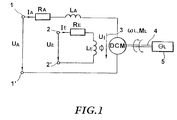
- FIG. 1 is an electromechanical equivalent circuit a DC drive shown. It will noted that the elements of the anchor circle with are provided with the index A, whereas the elements of the excitation circuit are provided with the index E.
- the armature circuit has two terminals 1, 1 ', between which the armature voltage U A is present.
- the terminal 1 is connected via the resistor R A and the inductance L A to a connection of a DC motor DCM.
- the other connection of the DC motor is connected to terminal 1 'of the armature circuit.
- Current I A flows in the armature circuit.
- the excitation circuit comprises two terminals 2, 2 ', between which the excitation voltage U E is applied.
- the resistance R E represents the resistance of the excitation winding and the inductance L E represents the inductance of the excitation winding.
- the current I E flows in the excitation circuit.
- U I (indicated by arrow 3) represents the speed-dependent back emf of the DCM motor.
- the motor DCM comprises an output shaft 4, which is connected to a load 5.
- the load is connected to the motor via a gear.
- the output shaft of the engine is hereinafter referred to as the input shaft and the output shaft of the transmission is referred to as the output shaft.
- ⁇ A denotes the speed of the drive shaft.
- M * L represents the load torque converted to the drive shaft and ⁇ * L denotes the moment of inertia of the load converted to the drive shaft.
- the armature voltage U A and the section modulus M * W ges represent the mathematical disturbance variables, the armature current I A the angular velocity ⁇ A being the state variables of the system.
- the current section modulus results from the solution of this differential equation system using the variables U A , I A and ⁇ that can be determined directly on the motor.
- a first parameter is the motor constant k 3 ⁇ , which is a direct parameter of the motor. This parameter can thus be determined directly during the development of the DC drive and used as a load-independent constant in the calculation.
- the angular velocity is recorded using a digital speed measurement.
- an incremental encoder can be used for speed measurement, which specifies a defined number of pulses per revolution.
- f L represents the average speed of the output shaft of the motor in the interval [t 0 -T M / 2, t 0 + T M / 2].
- the moment of inertia of the determined by the DC drive element become.
- the moment of inertia is from the respective one Depending on the application and therefore must be can be determined by learning drives of the drive.
- One or more learning runs are carried out on the drive to determine ⁇ L, tot.
- the moment of inertia results from the measured motor current and from the acceleration determined by evaluating the incremental encoder pulses.
- intervals [t 1 , t 1 + T] and [t 2 , t 2 + T] are determined during the learning trips in such a way that the mean moments of resistance with respect to the two intervals are the same.
- a conversion of the differential equation in relation to the output shaft provides the following relationship k 3rd ⁇ I.
- equation (38) can finally be written in a simplified form as With
- Equation (42) describes the size M W, sat the mean value of the section modulus for the interval [t 0 , t 0 + T].
- the mean section modulus for the interval [t 0 , t 0 + T] can be approximately determined according to equation (43).
- the method according to the invention thus first records two state variables of the DC drive and then determines that on the Resistive moment applied to the DC drive from the detected State variables and from parameters of the direct current drive and one driven by the DC drive Elements.
- the state variables include the Angular velocity and the armature current of the DC drive, and the parameters include the moment of inertia the element driven by the direct current drive and the motor constant of the DC drive itself.
- the for the determination of the section modulus required parameters become undisturbed during a learning operation DC drive determined and stored. Similar ones Way, the predetermined section modulus during a Learning operation of the undisturbed DC drive determined and saved.
- the abnormal situation represents the encounter with one Obstacle in the gate path and after determining this abnormal situation occurs a shutdown and / or an Reversing the DC drive.
- the mode of operation is described below with reference to FIGS. 2 to 4 of the inventive method explained in more detail.
- the occurrence of an abnormal Situation or a dangerous situation such as a Obstruction or blockage of the drive movement from which resulting increase in section modulus.
- the resistance element which is position-dependent in reality determined during an undisturbed journey and can be saved.
- the control is subsequently carried out by comparing the reference resistance moments and the currently determined section modulus.
- a constant friction or one depending on the position Friction (output side) is essential for the function of the process uncritical because the force generated by this during the Learn run determined and added to the target load torque can, or is included in the target load torque.
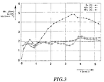
- Fig. 3 is the course of the motor current, the load torque and the rotational speed over time, where in this case the DC drive is not constant Speed was operated.
- the compensation of the starting current works even at non-constant speeds.
- the load increased by 40 N carried out.
- the change in the load torque is clear to recognize, whereas the motor current also by the acceleration and decelerations fluctuate widely subject to.
Landscapes
- Engineering & Computer Science (AREA)
- General Engineering & Computer Science (AREA)
- Mechanical Engineering (AREA)
- Control Of Electric Motors In General (AREA)
- Control Of Direct Current Motors (AREA)
- Control Of Motors That Do Not Use Commutators (AREA)
- Power-Operated Mechanisms For Wings (AREA)
- Control Of Stepping Motors (AREA)
- Elevator Door Apparatuses (AREA)
- Selective Calling Equipment (AREA)
Applications Claiming Priority (3)
| Application Number | Priority Date | Filing Date | Title |
|---|---|---|---|
| DE19601359A DE19601359A1 (de) | 1996-01-16 | 1996-01-16 | Verfahren zum Steuern eines Gleichstromantriebs |
| DE19601359 | 1996-01-16 | ||
| PCT/EP1996/005850 WO1997026694A1 (de) | 1996-01-16 | 1996-12-27 | Verfahren zum steuern eines gleichstromantriebs |
Publications (2)
| Publication Number | Publication Date |
|---|---|
| EP0857368A1 EP0857368A1 (de) | 1998-08-12 |
| EP0857368B1 true EP0857368B1 (de) | 1999-02-03 |
Family
ID=7782881
Family Applications (1)
| Application Number | Title | Priority Date | Filing Date |
|---|---|---|---|
| EP96944665A Expired - Lifetime EP0857368B1 (de) | 1996-01-16 | 1996-12-27 | Verfahren zum steuern eines gleichstromantriebs |
Country Status (9)
| Country | Link |
|---|---|
| US (1) | US6005361A (pl) |
| EP (1) | EP0857368B1 (pl) |
| AT (1) | ATE176557T1 (pl) |
| AU (1) | AU700051B2 (pl) |
| DE (2) | DE19601359A1 (pl) |
| HU (1) | HUP9903719A3 (pl) |
| NO (1) | NO312649B1 (pl) |
| PL (1) | PL182144B1 (pl) |
| WO (1) | WO1997026694A1 (pl) |
Families Citing this family (18)
| Publication number | Priority date | Publication date | Assignee | Title |
|---|---|---|---|---|
| DE29621617U1 (de) * | 1996-12-12 | 1997-03-13 | Siemens AG, 80333 München | Vorrichtung zur Überwachung und Begrenzung der statischen Schließkraft einer längsgeführt hin und her bewegbaren Masse |
| DE19925372A1 (de) | 1999-06-02 | 2000-12-07 | Bosch Gmbh Robert | Verfahren zum elektronischen Überwachen und Steuern eines Prozesses zum Verstellen beweglicher Teile |
| DE10119340A1 (de) | 2001-04-20 | 2002-10-31 | Stabilus Gmbh | Betätigungssystem für eine Klappe o. dergleichen |
| US6897630B2 (en) | 2002-08-16 | 2005-05-24 | Wayne-Dalton Corp. | System and related methods for sensing forces on a movable barrier |
| US7207142B2 (en) * | 2002-12-04 | 2007-04-24 | Wayne-Dalton Corp. | System and related methods for signaling the position of a movable barrier and securing its position |
| DE10310480B4 (de) * | 2003-03-11 | 2006-10-12 | Sommer Antriebs- Und Funktechnik Gmbh | Verfahren und Vorrichtung zum Steuern eines Torantriebes |
| US7592727B1 (en) | 2005-08-01 | 2009-09-22 | The United States Of America As Represented By The Secretary Of The Navy | Quiet load for motor testing |
| DE102008033866B4 (de) * | 2008-07-19 | 2023-06-15 | Festool Gmbh | Steuerungseinrichtung für einen elektrischen Antriebsmotor und Werkzeugmaschine |
| US10208529B2 (en) | 2009-06-23 | 2019-02-19 | Higher Power Hydraulic Doors, Llc | Tilt-up door |
| EP2653642B1 (de) * | 2012-04-20 | 2019-03-13 | Hawa Sliding Solutions AG | Verfahren für den betrieb eines faltsystems und faltsystem |
| FR3024176B1 (fr) * | 2014-07-25 | 2016-08-05 | Somfy Sas | Procede de controle d'un actionneur d'enroulement, actionneur d'enroulement configure pour un tel procede et installation de fermeture ou de protection solaire comprenant un tel actionneur |
| DE102016124079A1 (de) * | 2016-12-12 | 2018-06-14 | Phoenix Contact Gmbh & Co. Kg | Verfahren zur Überwachung einer elektromechanischen Komponente eines Automatisierungssystems |
| LU93350B1 (de) | 2016-12-12 | 2018-07-03 | Phoenix Contact Gmbh & Co Kg Intellectual Property Licenses & Standards | Verfahren zur Überwachung einer elektromechanischen Komponente eines Automatisierungssystems |
| EP4001569A1 (en) | 2020-11-17 | 2022-05-25 | Aptiv Technologies Limited | Pinch detection based on motor current increase |
| EP4001566B1 (en) * | 2020-11-17 | 2024-05-29 | Aptiv Technologies AG | Pinch detection during motor restart |
| EP4001567B1 (en) | 2020-11-17 | 2024-05-29 | Aptiv Technologies AG | Method and device for detecting potential pinches |
| EP4001568B1 (en) | 2020-11-17 | 2024-05-01 | Aptiv Technologies AG | Pinch detection based on estimated pinch force |
| EP4001565B1 (en) | 2020-11-17 | 2023-12-27 | Aptiv Technologies Limited | Method and device for detecting potential pinches |
Family Cites Families (14)
| Publication number | Priority date | Publication date | Assignee | Title |
|---|---|---|---|---|
| US4101831A (en) * | 1976-04-12 | 1978-07-18 | Rexnord Inc. | Load monitoring apparatus and method |
| JPS56123783A (en) * | 1980-02-29 | 1981-09-29 | Nippon Denso Co Ltd | Control unit for load driving |
| JP2530717B2 (ja) * | 1989-05-31 | 1996-09-04 | シャープ株式会社 | 電池電圧判別回路 |
| DE4000730A1 (de) * | 1990-01-12 | 1991-08-01 | Bosch Gmbh Robert | Verfahren und vorrichtung zum betreiben von fremdkraftbetaetigten teilen mit einklemmgefahr |
| US5180923A (en) * | 1990-11-01 | 1993-01-19 | Westinghouse Electric Corp. | Method and apparatus for downline load rejection sensing in a gas turbine control system |
| DE9202631U1 (de) * | 1992-02-28 | 1992-05-07 | Siemens AG, 8000 München | Einrichtung für die Überwachung der kinetischen Energie einer Schiebetür |
| US5351439A (en) * | 1992-04-21 | 1994-10-04 | Koito Manufacturing Co., Ltd. | Power window apparatus having improved safety device |
| US5334876A (en) * | 1992-04-22 | 1994-08-02 | Nartron Corporation | Power window or panel controller |
| DE4214998C2 (de) * | 1992-05-06 | 1995-06-29 | Prettl Rolf | Torantrieb und Verfahren zum Betreiben eines Torantriebes |
| JP2871993B2 (ja) * | 1993-03-31 | 1999-03-17 | 日本電気株式会社 | サーボモータの位置制御装置 |
| DE4333675A1 (de) * | 1993-10-02 | 1995-04-06 | Bosch Gmbh Robert | Elektromotor mit Mitteln zur Erfassung des Drehmoments |
| EP0692856A3 (en) * | 1994-07-14 | 1997-10-08 | Nartron Corp | Controller for a window regulator or a panel |
| DE4442171A1 (de) * | 1994-11-26 | 1996-06-13 | Telefunken Microelectron | Verfahren zur Überwachung des Öffnungs- und Schließvorgangs bei einem System mit mindestens einem elektromotorisch bewegten Teil |
| JPH08248104A (ja) * | 1995-03-10 | 1996-09-27 | Toyota Motor Corp | 電動機性能試験装置 |
-
1996
- 1996-01-16 DE DE19601359A patent/DE19601359A1/de not_active Withdrawn
- 1996-12-27 AT AT96944665T patent/ATE176557T1/de not_active IP Right Cessation
- 1996-12-27 US US09/117,051 patent/US6005361A/en not_active Expired - Fee Related
- 1996-12-27 HU HU9903719A patent/HUP9903719A3/hu unknown
- 1996-12-27 EP EP96944665A patent/EP0857368B1/de not_active Expired - Lifetime
- 1996-12-27 AU AU13067/97A patent/AU700051B2/en not_active Ceased
- 1996-12-27 DE DE59601282T patent/DE59601282D1/de not_active Expired - Fee Related
- 1996-12-27 PL PL96328000A patent/PL182144B1/pl not_active IP Right Cessation
- 1996-12-27 WO PCT/EP1996/005850 patent/WO1997026694A1/de not_active Ceased
-
1998
- 1998-07-15 NO NO19983272A patent/NO312649B1/no unknown
Also Published As
| Publication number | Publication date |
|---|---|
| EP0857368A1 (de) | 1998-08-12 |
| PL182144B1 (pl) | 2001-11-30 |
| WO1997026694A1 (de) | 1997-07-24 |
| NO983272D0 (no) | 1998-07-15 |
| NO983272L (no) | 1998-09-16 |
| DE19601359A1 (de) | 1997-07-17 |
| AU1306797A (en) | 1997-08-11 |
| DE59601282D1 (de) | 1999-03-18 |
| ATE176557T1 (de) | 1999-02-15 |
| NO312649B1 (no) | 2002-06-10 |
| US6005361A (en) | 1999-12-21 |
| HUP9903719A3 (en) | 2000-05-29 |
| AU700051B2 (en) | 1998-12-17 |
| PL328000A1 (en) | 1999-01-04 |
| HUP9903719A2 (hu) | 2000-03-28 |
Similar Documents
| Publication | Publication Date | Title |
|---|---|---|
| EP0857368B1 (de) | Verfahren zum steuern eines gleichstromantriebs | |
| EP0890841B1 (de) | Verfahren zum Ermitteln der Drehzahl bei mechanisch kommutierten Gleichstrommotoren | |
| DE19839025C2 (de) | Hindernis-Nachweisverfahren für eine elektrische Fensterhebervorrichtung | |
| EP0899847B1 (de) | Verfahren zur Erkennung der Position und der Bewegungsrichtung eines bewegbar gelagerten Teils an einem elektrischen Motor | |
| EP0690556B1 (de) | Stillstandserkennung beim Wiederanlassen eines stromrichtergespeisten Drehstrommotors ohne Drehzahlgeber | |
| DE102007019798A1 (de) | Verfahren zum Steuern eines elektrischen Türantriebes | |
| DE69936222T2 (de) | System und verfahren zum schutz eines elektromotors und dessen ansteuerschaltung, und ein elektromotor | |
| WO2009043705A1 (de) | Verfahren und vorrichtung zum ausgleich von fertigungsbedingten ungenauigkeiten des magnetrades eines elektromotorischen antriebs eines fahrzeugs | |
| EP0976675B2 (de) | Verfahren zur Kraftbegrenzung für automatische Aufzugstüren | |
| DE19838144A1 (de) | Verfahren zum Nachweisen eines Hindernisses für ein Fenster mit elektrischem Fensterheber | |
| EP2343797B1 (de) | Einphasiger elektronisch kommutierter Motor | |
| WO2017167908A1 (de) | Verfahren zur bestimmung des drehwinkels bei einem elektromotor | |
| WO2002095924A1 (de) | Verfahren zum korrigieren einer drehstellungsbestimmung einer antriebswelle eines kommutierten gleichstrommotors | |
| DE202008004451U1 (de) | Verstelleinrichtung | |
| DE102016205325A1 (de) | Stellvorrichtung für ein verstellbares Fahrzeugteil und Verfahren zum Betrieb einer solchen | |
| DE102006059145B4 (de) | Verfahren und Einrichtung zum Ermitteln einer von einem Elektromotor hergeleiteten Antriebskraft | |
| EP2102725A1 (de) | Verfahren und vorrichtung zum verfolgen der position einer von einem elektromotor angetriebenen komponente | |
| DE102013226143B3 (de) | Verfahren zur Erfassung eines Belastungseinbruchs eines elektrischen Hilfsantriebs, Steuerverfahren für einen elektrischen Hilfsantrieb eines Fahrrads und Hilfsantriebssteuerung für einen elektrischen Hilfsantrieb | |
| DE3528409A1 (de) | Verfahren und vorrichtung zum rberwachen des lastzustandes einer rotierenden mechanik, die von einer feldorientierten drehfeldmaschine angetrieben ist | |
| DE10042169B4 (de) | Verfahren zum Ermitteln eines maximal zulässigen Motormoments | |
| DE4322146A1 (de) | Verwendung eines elektrischen Antriebes für Bearbeitungsspindeln und Vorschubachsen an Werkzeugmaschinen | |
| EP1879289B1 (de) | Drehwinkelbestimmung eines Elektromotors | |
| DE102009019183B4 (de) | Interpolationsverfahren zur Überbrückung der Freilaufphase eines Stellvorgangs | |
| EP1745337B1 (de) | Verfahren und schaltungsanordnung zur elektrischen steuerung und/oder regelung der bewegung eines elektrisch betriebenen aggregats | |
| EP3406026B1 (de) | Überwachung des betriebszustandes von synchronmotoren |
Legal Events
| Date | Code | Title | Description |
|---|---|---|---|
| PUAI | Public reference made under article 153(3) epc to a published international application that has entered the european phase |
Free format text: ORIGINAL CODE: 0009012 |
|
| GRAG | Despatch of communication of intention to grant |
Free format text: ORIGINAL CODE: EPIDOS AGRA |
|
| GRAG | Despatch of communication of intention to grant |
Free format text: ORIGINAL CODE: EPIDOS AGRA |
|
| GRAH | Despatch of communication of intention to grant a patent |
Free format text: ORIGINAL CODE: EPIDOS IGRA |
|
| 17P | Request for examination filed |
Effective date: 19980603 |
|
| AK | Designated contracting states |
Kind code of ref document: A1 Designated state(s): AT CH DE DK FI FR GB IT LI SE |
|
| 17Q | First examination report despatched |
Effective date: 19980728 |
|
| GRAH | Despatch of communication of intention to grant a patent |
Free format text: ORIGINAL CODE: EPIDOS IGRA |
|
| GRAA | (expected) grant |
Free format text: ORIGINAL CODE: 0009210 |
|
| ITF | It: translation for a ep patent filed | ||
| AK | Designated contracting states |
Kind code of ref document: B1 Designated state(s): AT CH DE DK FI FR GB IT LI SE |
|
| REF | Corresponds to: |
Ref document number: 176557 Country of ref document: AT Date of ref document: 19990215 Kind code of ref document: T |
|
| REG | Reference to a national code |
Ref country code: CH Ref legal event code: EP |
|
| GBT | Gb: translation of ep patent filed (gb section 77(6)(a)/1977) |
Effective date: 19990204 |
|
| REF | Corresponds to: |
Ref document number: 59601282 Country of ref document: DE Date of ref document: 19990318 |
|
| ET | Fr: translation filed | ||
| REG | Reference to a national code |
Ref country code: CH Ref legal event code: NV Representative=s name: PATENTANWAELTE GEORG ROEMPLER UND ALDO ROEMPLER |
|
| REG | Reference to a national code |
Ref country code: DK Ref legal event code: T3 |
|
| PLBE | No opposition filed within time limit |
Free format text: ORIGINAL CODE: 0009261 |
|
| STAA | Information on the status of an ep patent application or granted ep patent |
Free format text: STATUS: NO OPPOSITION FILED WITHIN TIME LIMIT |
|
| 26N | No opposition filed | ||
| REG | Reference to a national code |
Ref country code: GB Ref legal event code: IF02 |
|
| PGFP | Annual fee paid to national office [announced via postgrant information from national office to epo] |
Ref country code: FR Payment date: 20021213 Year of fee payment: 7 |
|
| PGFP | Annual fee paid to national office [announced via postgrant information from national office to epo] |
Ref country code: DK Payment date: 20021217 Year of fee payment: 7 Ref country code: AT Payment date: 20021217 Year of fee payment: 7 |
|
| PGFP | Annual fee paid to national office [announced via postgrant information from national office to epo] |
Ref country code: SE Payment date: 20021218 Year of fee payment: 7 Ref country code: FI Payment date: 20021218 Year of fee payment: 7 |
|
| PGFP | Annual fee paid to national office [announced via postgrant information from national office to epo] |
Ref country code: CH Payment date: 20021219 Year of fee payment: 7 |
|
| PGFP | Annual fee paid to national office [announced via postgrant information from national office to epo] |
Ref country code: GB Payment date: 20031120 Year of fee payment: 8 |
|
| PG25 | Lapsed in a contracting state [announced via postgrant information from national office to epo] |
Ref country code: FI Free format text: LAPSE BECAUSE OF NON-PAYMENT OF DUE FEES Effective date: 20031227 Ref country code: AT Free format text: LAPSE BECAUSE OF NON-PAYMENT OF DUE FEES Effective date: 20031227 |
|
| PG25 | Lapsed in a contracting state [announced via postgrant information from national office to epo] |
Ref country code: SE Free format text: LAPSE BECAUSE OF NON-PAYMENT OF DUE FEES Effective date: 20031228 |
|
| PG25 | Lapsed in a contracting state [announced via postgrant information from national office to epo] |
Ref country code: LI Free format text: LAPSE BECAUSE OF NON-PAYMENT OF DUE FEES Effective date: 20031231 Ref country code: CH Free format text: LAPSE BECAUSE OF NON-PAYMENT OF DUE FEES Effective date: 20031231 |
|
| PG25 | Lapsed in a contracting state [announced via postgrant information from national office to epo] |
Ref country code: DK Free format text: LAPSE BECAUSE OF NON-PAYMENT OF DUE FEES Effective date: 20040102 |
|
| REG | Reference to a national code |
Ref country code: CH Ref legal event code: PFA Owner name: FRAUNHOFER-GESELLSCHAFT ZUR FOERDERUNG DER ANGEWA Free format text: FRAUNHOFER-GESELLSCHAFT ZUR FOERDERUNG DER ANGEWANDTEN FORSCHUNG E.V.#LEONRODSTRASSE 54#80636 MUENCHEN (DE) -TRANSFER TO- FRAUNHOFER-GESELLSCHAFT ZUR FOERDERUNG DER ANGEWANDTEN FORSCHUNG E.V.#HANSASTRASSE 27 C#80686 MUENCHEN (DE) |
|
| EUG | Se: european patent has lapsed | ||
| REG | Reference to a national code |
Ref country code: CH Ref legal event code: PL |
|
| REG | Reference to a national code |
Ref country code: DK Ref legal event code: EBP |
|
| PG25 | Lapsed in a contracting state [announced via postgrant information from national office to epo] |
Ref country code: FR Free format text: LAPSE BECAUSE OF NON-PAYMENT OF DUE FEES Effective date: 20040831 |
|
| REG | Reference to a national code |
Ref country code: FR Ref legal event code: ST |
|
| PG25 | Lapsed in a contracting state [announced via postgrant information from national office to epo] |
Ref country code: GB Free format text: LAPSE BECAUSE OF NON-PAYMENT OF DUE FEES Effective date: 20041227 |
|
| GBPC | Gb: european patent ceased through non-payment of renewal fee |
Effective date: 20041227 |
|
| PG25 | Lapsed in a contracting state [announced via postgrant information from national office to epo] |
Ref country code: IT Free format text: LAPSE BECAUSE OF NON-PAYMENT OF DUE FEES;WARNING: LAPSES OF ITALIAN PATENTS WITH EFFECTIVE DATE BEFORE 2007 MAY HAVE OCCURRED AT ANY TIME BEFORE 2007. THE CORRECT EFFECTIVE DATE MAY BE DIFFERENT FROM THE ONE RECORDED. Effective date: 20051227 |
|
| PGFP | Annual fee paid to national office [announced via postgrant information from national office to epo] |
Ref country code: DE Payment date: 20070523 Year of fee payment: 11 |
|
| PG25 | Lapsed in a contracting state [announced via postgrant information from national office to epo] |
Ref country code: DE Free format text: LAPSE BECAUSE OF NON-PAYMENT OF DUE FEES Effective date: 20080701 |