EP0856432A2 - Anzeigevorrichtung innerhalb eines Fahrzeuges - Google Patents
Anzeigevorrichtung innerhalb eines Fahrzeuges Download PDFInfo
- Publication number
- EP0856432A2 EP0856432A2 EP98101546A EP98101546A EP0856432A2 EP 0856432 A2 EP0856432 A2 EP 0856432A2 EP 98101546 A EP98101546 A EP 98101546A EP 98101546 A EP98101546 A EP 98101546A EP 0856432 A2 EP0856432 A2 EP 0856432A2
- Authority
- EP
- European Patent Office
- Prior art keywords
- actuating element
- terminals
- vehicle
- steering wheel
- pair
- Prior art date
- Legal status (The legal status is an assumption and is not a legal conclusion. Google has not performed a legal analysis and makes no representation as to the accuracy of the status listed.)
- Withdrawn
Links
Images


Classifications
-
- B—PERFORMING OPERATIONS; TRANSPORTING
- B62—LAND VEHICLES FOR TRAVELLING OTHERWISE THAN ON RAILS
- B62D—MOTOR VEHICLES; TRAILERS
- B62D1/00—Steering controls, i.e. means for initiating a change of direction of the vehicle
- B62D1/02—Steering controls, i.e. means for initiating a change of direction of the vehicle vehicle-mounted
- B62D1/04—Hand wheels
- B62D1/046—Adaptations on rotatable parts of the steering wheel for accommodation of switches
-
- B—PERFORMING OPERATIONS; TRANSPORTING
- B60—VEHICLES IN GENERAL
- B60Q—ARRANGEMENT OF SIGNALLING OR LIGHTING DEVICES, THE MOUNTING OR SUPPORTING THEREOF OR CIRCUITS THEREFOR, FOR VEHICLES IN GENERAL
- B60Q9/00—Arrangement or adaptation of signal devices not provided for in one of main groups B60Q1/00 - B60Q7/00, e.g. haptic signalling
-
- B—PERFORMING OPERATIONS; TRANSPORTING
- B62—LAND VEHICLES FOR TRAVELLING OTHERWISE THAN ON RAILS
- B62D—MOTOR VEHICLES; TRAILERS
- B62D15/00—Steering not otherwise provided for
- B62D15/02—Steering position indicators ; Steering position determination; Steering aids
- B62D15/029—Steering assistants using warnings or proposing actions to the driver without influencing the steering system
Definitions
- the present invention relates to an inside indicating device for a vehicle.
- Optical indicating devices comprise standard rear-lighted graphic symbols on the dashboard, each indicating a respective operating quantity of the vehicle.
- a high noise level inside and/or outside the vehicle may prevent the driver from hearing the sound signal emitted by acoustic indicating devices.
- an inside indicating device for a vehicle characterized by comprising touch indicating means.
- the invention is based on the principle of employing mechanical-vibration generating elements located adjacent to the driver's seat, e.g. on the steering wheel of the vehicle, and generating mechanical vibrations perceivable by touch and ear by the driver while the vehicle is running, and which represent driver touch signals to which are assigned messages relating to operation of the vehicle or other vehicle-related situations.
- the touch signals supplied by the mechanical-vibration generating elements may be used, for example, for driver-assist purposes, to prevent the vehicle from drifting off the road as a result of distraction or fatigue on the part of the driver, to which application the following description refers purely by way of example.
- the touch signals may also be used, however, to alert the driver of vehicle operating conditions, such as speeding, or to indicate the vehicle is approaching a dangerous junction or traffic jam, if the vehicle is designed to cooperate with navigation systems indicating the road network location of the vehicle, maximum permissible speed, and road traffic conditions.
- Number 1 in Figure 1 indicates as a whole an indicating device according to a first embodiment of the present invention and connected to a device 2 for monitoring and indicating operating conditions of the vehicle (not shown).
- the monitoring and indicating device 2 comprises a television camera 5 housed in a front portion of the vehicle and generating, at an output terminal 6, a television signal T relative to the road scene ahead of the vehicle; and a processing unit 7 for controlling indicating device 1, and having a first input terminal 8 connected to output terminal 6 of camera 5, and a first and a second output terminals 9, 10 connected to indicating device 1.
- Processing unit 7 also receives, at a second input terminal 11, a speed signal V correlated with the speed of the vehicle; at a third input terminal 12, a position signal ⁇ correlated with the angular position of the steering wheel 13 of the vehicle; and, at a fourth and fifth input terminal 14, 15, respective first and second direction signals S, D respectively indicating operation of the left and right direction indicators (not shown) of the vehicle.
- Processing unit 7 also receives, at a sixth input terminal 16, an alarm signal A generated by indicating device 1 as described in detail later on, and, on the basis of speed signal V, position signal ⁇ and direction signals S, D, generates a first enabling signal S1 at the first output terminal 9, and a second enabling signal S2 at the second output terminal 10, both of which signals are supplied to indicating device 1.
- Indicating device 1 comprises a pair of piezoelectric actuating elements 20 - hereinafter referred to as "piezoelectric elements" - located on steering wheel 13 of the vehicle, and each having a pair of connecting terminals 21; a drive unit 22 for driving piezoelectric elements 20 and enabled by processing unit 7; and a monitoring unit 23 for monitoring operation of piezoelectric elements 20 and also enabled by processing unit 7 as described in detail later on.
- drive unit 22 has a control terminal 25 connected to first output terminal 9 of processing unit 7, and for receiving first enabling signal S1 generated by processing unit 7; and a first and second pair of output terminals 26, 27, each connected to a respective pair of terminals 21 of a respective piezoelectric element 20.
- Monitoring unit 23 has a control terminal 30 connected to second output terminal 10 of processing unit 7, and for receiving second enabling signal S2 generated by processing unit 7; a first and second pair of input terminals 31, 32, each connected to a respective pair of terminals 21 of a respective piezoelectric element 20; and an output terminal 33 connected to sixth input terminal 16 of processing unit 7.
- drive unit 22 when enabled, provides for activating piezoelectric elements 20, while monitoring unit 23 provides for generating alarm signal A at output terminal 33, in the event the driver's hands are not placed correctly on the portions of steering wheel 13 housing piezoelectric elements 20, by performing the operations described in detail later on with reference to Figure 2.
- piezoelectric elements 20 are located, as shown in Figure 1, in the rim 35 of steering wheel 13, in particular, in diametrically-opposed portions 35a, 35b of rim 35 normally gripped by the driver; and each piezoelectric element 20 is conveniently concealed beneath the outer covering of respective portion 35a, 35b of rim 35.
- piezoelectric elements 20 Operation of piezoelectric elements 20 is based on the known piezoelectricity phenomenon, which occurs in crystals with an asymmetrically structured lattice, and whereby the crystals are polarized electrically when subjected to mechanical stress (direct piezoelectric effect) and are distorted when placed in an electric field (inverse piezoelectric effect).
- the resonance frequency of a piezoelectric crystal is defined by the characteristic elastic vibration frequency of the ceramic material of which it is formed, and depends, among other things, on the form of the crystal.
- piezoelectric elements 20 are bimorph ceramic plate elements of series or parallel type, are 35 mm x 12 mm x 0.6 mm in size, have a resonance frequency of about 250 Hz, and a maximum mechanical oscillation deflection of about 1 mm.
- Piezoelectric elements 20 of the above type were chosen for their resonance frequency, which is that to which the skin of the hand is most sensitive, and which falls within the human hearing range. At such a resonance frequency, in fact, the hand is capable of detecting mechanical vibrations with mechanical oscillation deflections of at least 0.6 *m, and the mechanical vibrations generated by piezoelectric elements 20 are also perceivable by ear.
- Drive unit 22 controls each piezoelectric element 20 by supplying between connecting terminals 21 a respective alternating control signal C1, C2 of appropriate amplitude and a frequency equal or close to the resonance frequency of piezoelectric element 20.
- the control signal C1, C2 of each piezoelectric element 20 is preferably a square-wave voltage signal, though laboratory tests have shown that, as regards feeling and hearing the mechanical vibrations generated by the piezoelectric elements, substantially the same results are obtained using sinusoidal, pulsated or triangular-wave signals.
- each piezoelectric element 20 with a square-wave control signal C1, C2 of, not only a frequency equal to or close to the resonance frequency of piezoelectric element 20, but also an amplitude of about 100 Vpp (peak-to-peak volts).
- the touch and audio signal supplied to the driver depends largely on how steering wheel 13 is gripped, and the combined touch-audio effect is regulated by the placement of the driver's hands on steering wheel 13.
- the characteristics of piezoelectric elements 20 described above are such that, if rim 35 of steering wheel 13 is gripped correctly at portions 35a, 35b housing piezoelectric elements 20, i.e. if said portions are subjected by the driver to compression typical of that applied when driving the vehicle, the peak-to-peak amplitude of control signal C1, C2 between terminals 21 of each piezoelectric element 20 assumes a given value, whereas, if rim 35 of steering wheel 13 is not gripped correctly at portions 35a, 35b housing piezoelectric elements 20, i.e. if said portions are not subjected to such compression, the peak-to-peak amplitude of control signal C1, C2 between terminals 21 of each piezoelectric element 20 assumes a different value from the previous one.
- the amplitude of control signal C1, C2 between terminals 21 of piezoelectric elements 20, when steering wheel 13 is gripped correctly by the driver is about 2-3% higher than the amplitude detected when steering wheel 13 is not gripped correctly; which variation in amplitude is due to a variation in the impedance of piezoelectric elements 20 when compressed by the driver.
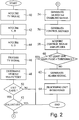
- monitoring unit 23 which acquires the control signals C1, C2 supplied to piezoelectric elements 20, and determines whether steering wheel 13 is gripped correctly or not by the driver by performing the operations described below with reference to the Figure 2 flow chart.
- processing unit 7 first acquires the television signal T generated by camera 5 and relative to the road scene ahead of the vehicle (block 40).
- Processing unit 7 then acquires speed signal V indicating the speed of the vehicle, and position signal ⁇ indicating the angular position of steering wheel 13 (block 42).
- Processing unit 7 then acquires direction signals S, D respectively indicating operation of the left and right direction indicators of the vehicle (block 44).
- Processing unit 7 then processes television signal T by means of known image processing techniques not described in detail, and determines the geometry of the road ahead of the vehicle, which is defined by the traffic lane and by the position of the vehicle within the lane (block 46).
- processing unit 7 determines the trajectory of the vehicle (block 48).
- processing unit 7 compares the vehicle trajectory determined in block 48 with the geometry of the road determined in block 46, to determine whether or not the vehicle is about to move out of the lane (block 50).
- processing unit 7 determines, on the basis of direction signals S, D, whether the move is voluntary, i.e. controlled by the driver (block 52).
- processing unit 7 determines whether the move is voluntary by determining activation by the driver of the direction indicator corresponding to the direction in which the vehicle is moving out of the lane.
- drive unit 22 On receiving first enabling signal S1, drive unit 22 generates control signals C1, C2 of the type described above for piezoelectric elements 20 (block 56).
- piezoelectric elements 20 generate mechanical vibrations perceivable by touch and ear by the driver, who is thus alerted that the vehicle is about to move out of the lane.
- monitoring unit 23 acquires the control signals C1, C2 supplied to terminals 21 of piezoelectric elements 20 (block 58).
- Monitoring unit 23 compares the amplitude of each control signal C1, C2 with a predetermined threshold value C th representing the amplitude which the control signal would have if no compression were exerted on the piezoelectric elements, i.e. if steering wheel 13 were not gripped correctly by the driver at portions 35a, 35b of rim 35 housing piezoelectric elements 20 (block 60).
- processing unit 7 on receiving the alarm signal, intervenes, for example, by increasing the intensity of the acoustic signal generated by piezoelectric elements 20, or by enabling special automatic control devices on the vehicle (block 64).
- Figures 3 and 4 show a second embodiment of the indicating device according to the present invention.
- the indicating device - in this case indicated 1' - differs from indicating device 1 by piezoelectric elements 20 being replaced by an actuator 70 comprising a motor 71, which has an output shaft 72, of axis A, carrying an eccentric mass 74, preferably of heavy metal, i.e. a mass so connected to output shaft 72 that the center of gravity of the mass is located along an axis B parallel to axis A of output shaft 72.
- an actuator 70 comprising a motor 71, which has an output shaft 72, of axis A, carrying an eccentric mass 74, preferably of heavy metal, i.e. a mass so connected to output shaft 72 that the center of gravity of the mass is located along an axis B parallel to axis A of output shaft 72.
- Motor 71 may, for example, be of the type used for powering vehicle rearview mirrors, and is preferably fitted to the metal part of one of the spokes 76 of steering wheel 13 joining the central housing 78 to rim 35, leaving enough room for eccentric mass 74 to rotate freely.
- Motor 71 has a pair of terminals 79 connected to output terminals 26 of drive unit 22, and is driven by drive unit 22 with the consent of processing unit 7.
- drive unit 22 On receiving enabling signal S1 generated by processing unit 7, drive unit 22 generates between output terminals 26 a direct-voltage control signal C1, in particular, a control signal C1 defined by a direct voltage equal to the voltage supplied by the vehicle battery (not shown).
- control signal C1 When control signal C1 is supplied between terminals 79 of motor 71, i.e. when motor 71 is supplied with the battery voltage, motor 71 is activated and eccentric mass 74 is rotated to produce an intense vibration, which is transmitted via spoke 76 to rim 35 of steering wheel 13 and is felt clearly by the driver gripping steering wheel 13, regardless of which portion of rim 35 is gripped.
- Indicating device 1' also differs from device 1 by comprising no monitoring unit 23, and therefore dispensing with the operations, described with reference to blocks 60-64 in Figure 2, for determining correct gripping of steering wheel 13.
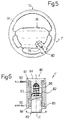
- Figures 5 and 6 show a third embodiment of the indicating device according to the present invention.
- the indicating device - in this case indicated 1'' - differs from indicating device 1 by piezoelectric elements 20 being replaced by an actuator 80 comprising a solenoid 82, which has a cavity 83, of axis C, closed at one end by a closing element 84 inserted partly inside cavity 83; a piston 85 made of ferromagnetic material and housed in axially-sliding manner in the remaining part of cavity 83; and an expulsion spring 86 interposed between closing element 84 and piston 85.
- an actuator 80 comprising a solenoid 82, which has a cavity 83, of axis C, closed at one end by a closing element 84 inserted partly inside cavity 83; a piston 85 made of ferromagnetic material and housed in axially-sliding manner in the remaining part of cavity 83; and an expulsion spring 86 interposed between closing element 84 and piston 85.
- Solenoid 82 is housed inside a substantially cup-shaped supporting structure 87 having a bottom wall 88 with a central hole through which piston 85 extends.
- Actuator 80 is preferably fitted to one of the spokes 76 of steering wheel 13 joining the central housing 78 to rim 35, and piston 85 is normally maintained by expulsion spring 86 in a partially extracted position with respect to cavity 83 and supporting structure 87, and in which piston 85 projects partially from cavity 83 and rests on a stop element 89 (e.g. a wall) outside supporting structure 87.
- a stop element 89 e.g. a wall
- Solenoid 82 has a pair of terminals 90 connected to output terminals 26 of drive unit 22, and is driven by drive unit 22 with the consent of processing unit 7.
- drive unit 22 On receiving enabling signal S1 generated by processing unit 7, drive unit 22 generates between output terminals 26 an alternating-voltage control signal C1, in particular, a control signal C1 defined by a train of pulses of appropriate amplitude and frequency.
- alternating-voltage control signal C1 may have an amplitude varying between a positive value (12 V) and zero, and a frequency of about 100 Hz.
- control signal C1 When control signal C1 is supplied between terminals 90 of solenoid 82, an alternating magnetic field is generated in solenoid 82 to move piston 85 back and forth.
- the intensity of the alternating magnetic field in the solenoid is such that piston 85 is alternately drawn inside solenoid 82, thus compressing expulsion spring 86, and then pushed out of solenoid 82 by expulsion spring 86 to project partly from supporting structure 87 and contact stop element 89.
- Indicating device 1'' also differs from device 1 by comprising no monitoring unit 23, and therefore dispensing with the operations, described with reference to blocks 60-64 in Figure 2, for determining correct gripping of steering wheel 13.
- indicating device 1, 1', 1'' provides for creating a new, combined tactile-acoustic channel of communication with the driver, and for supplying the driver with tactile information perceivable in any inside and/or outside lighting or noise conditions.
- indicating device 1, 1', 1'' is reliable, easy to implement, and involves only minor changes to the vehicle.
- each portion 35a, 35b of rim 35 of steering wheel 13 may be other than as described, and each portion 35a, 35b may be fitted with a number of piezoelectric elements 20 to cover a larger portion of rim 35.
- Piezoelectric elements 20 may be replaced by a single annular piezoelectric element extending about the whole of rim 35 to supply the driver with touch signals regardless of the position of the driver's hands on steering wheel 13.
- drive unit 22 only generates a first control signal C1; and monitoring unit 23, when enabled, only acquires first control signal C1, compares first control signal C1 with predetermined threshold value C th , and determines correct grip of steering wheel 13 when the amplitude of first control signal C1 is greater than threshold value C th and outside said tolerance window centered about threshold value C th , and incorrect grip of steering wheel 13 when the amplitude of first control signal C1 falls within the tolerance window.
- drive unit 22 and monitoring unit 23 may be dispensed with and the respective functions performed directly by processing unit 7.
- Piezoelectric elements 20 may be located in positions other than those described, and in particular in any position on the vehicle, adjacent to the driver's seat, in which the mechanical vibrations generated by them are perceivable by the driver by touch and ear, e.g. on the driver's seat (both the seat portion and backrest) or on the vehicle control pedals (accelerator, brake, clutch).
- the vibration frequency of the mechanical vibrations generated by piezoelectric elements 20 may be below the range of human hearing; and the amplitude and frequency of control signals C1 and C2 may be other than as described, and be correlated, for example, to the desired intensity of the vibrations to be transmitted to the driver.
Landscapes
- Engineering & Computer Science (AREA)
- Mechanical Engineering (AREA)
- Chemical & Material Sciences (AREA)
- Combustion & Propulsion (AREA)
- Transportation (AREA)
- Human Computer Interaction (AREA)
- General Electrical Machinery Utilizing Piezoelectricity, Electrostriction Or Magnetostriction (AREA)
- Apparatuses For Generation Of Mechanical Vibrations (AREA)
- Non-Portable Lighting Devices Or Systems Thereof (AREA)
- Document Processing Apparatus (AREA)
- Iron Core Of Rotating Electric Machines (AREA)
- Steering Controls (AREA)
Applications Claiming Priority (2)
| Application Number | Priority Date | Filing Date | Title |
|---|---|---|---|
| ITTO970071 IT1291484B1 (it) | 1997-01-31 | 1997-01-31 | Dispositivo di segnalazione interna per un autoveicolo. |
| ITTO970071 | 1997-01-31 |
Publications (2)
| Publication Number | Publication Date |
|---|---|
| EP0856432A2 true EP0856432A2 (de) | 1998-08-05 |
| EP0856432A3 EP0856432A3 (de) | 1999-05-26 |
Family
ID=11415289
Family Applications (1)
| Application Number | Title | Priority Date | Filing Date |
|---|---|---|---|
| EP98101546A Withdrawn EP0856432A3 (de) | 1997-01-31 | 1998-01-29 | Anzeigevorrichtung innerhalb eines Fahrzeuges |
Country Status (2)
| Country | Link |
|---|---|
| EP (1) | EP0856432A3 (de) |
| IT (1) | IT1291484B1 (de) |
Cited By (34)
| Publication number | Priority date | Publication date | Assignee | Title |
|---|---|---|---|---|
| EP1142746A2 (de) * | 2000-04-04 | 2001-10-10 | FERRARI S.p.A. | Fahrzeuglenkung |
| WO2002009978A1 (de) * | 2000-07-29 | 2002-02-07 | Robert Bosch Gmbh | Verfahren und system zur akustischen funktionssteuerung im kraftfahrzeug |
| FR2828155A1 (fr) | 2001-08-01 | 2003-02-07 | Peugeot Citroen Automobiles Sa | Dispositif d'alarme par vibration destine a informer un conducteur de vehicule automobile |
| FR2828154A1 (fr) | 2001-08-01 | 2003-02-07 | Peugeot Citroen Automobiles Sa | Dispositif d'alarme par vibration pour information d'un conducteur de vehicule automobile |
| WO2003078210A1 (de) * | 2002-03-18 | 2003-09-25 | Siemens Aktiengesellschaft | Steuer- oder schaltelement für fahrzeuge |
| EP1359486A1 (de) * | 2002-05-04 | 2003-11-05 | Audi Ag | Lenkrad, Informationssystem und Verfahren zur Informationsausgabe |
| EP1410972A2 (de) * | 2002-10-18 | 2004-04-21 | TRW Automotive Safety Systems GmbH | Fahrzeuglenkvorrichtung und Sicherheitssystem |
| DE102005014111A1 (de) * | 2005-03-22 | 2006-09-28 | Valeo Schalter Und Sensoren Gmbh | Schalteinrichtung mit einem Schalthebel, insbesondere für ein Fahrzeug |
| GB2426316A (en) * | 2005-05-18 | 2006-11-22 | Autoliv Dev | Steering wheel having moveable element activated in response to driver tiredness. |
| US7280046B2 (en) | 2005-06-15 | 2007-10-09 | Delphi Technologies, Inc. | Steering system with haptic driver warning |
| FR2910105A1 (fr) * | 2006-12-19 | 2008-06-20 | Peugeot Citroen Automobiles Sa | Dispositif d'avertissement de l'imminence d'un changement de rapport de vitesse d'un vehicule |
| EP1939062A1 (de) | 2006-12-28 | 2008-07-02 | MAGNETI MARELLI SISTEMI ELETTRONICI S.p.A. | Tast-/Tonsignalanordnung zum Warnen des Fahrers eines Fahrzeugs sowie eine Lenkvorrichtung für ein Fahrzeug und ein Fahrerassistenzsystem mit einer solchen Anordnung |
| EP1939061A1 (de) | 2006-12-28 | 2008-07-02 | MAGNETI MARELLI SISTEMI ELETTRONICI S.p.A. | Tastsignalanordnung zum Warnen des Fahrers eines Fahrzeugs sowie eine Lenkvorrichtung für ein Fahrzeug und ein Fahrerassistenzsystem mit einer solchen Anordnung |
| WO2008123804A1 (en) * | 2007-04-05 | 2008-10-16 | Autoliv Development Ab | Driver alert device |
| DE102007024140A1 (de) * | 2007-05-23 | 2008-11-27 | Takata-Petri Ag | Vibratorbaugruppe für ein Kraftfahrzeug |
| EP2014504A1 (de) * | 2007-07-11 | 2009-01-14 | Deere & Company | Bedienvorrichtung zum Ansteuern mindestens einer Zustandsgröße eines landwirtschaftlichen oder industriellen Nutzfahrzeugs |
| EP2014503A1 (de) * | 2007-07-11 | 2009-01-14 | Deere & Company | Bedienvorrichtung zum Ansteuern mindestens einer Zustandsgröße eines landwirtschaftlichen oder industriellen Nutzfahrzeugs |
| DE202007013477U1 (de) | 2007-09-25 | 2009-02-26 | Autoliv Development Ab | Fahrer-Alarmsystem für das Lenkrad eines Motorfahrzeugs |
| DE202007014209U1 (de) | 2007-10-10 | 2009-02-26 | Autoliv Development Ab | Fahrer-Alarmsystem für das Lenkrad eines Motorfahrzeugs |
| DE102010029860A1 (de) * | 2010-06-04 | 2011-12-08 | Brose Fahrzeugteile Gmbh & Co. Kommanditgesellschaft, Coburg | Warnsystem für ein Kraftfahrzeug |
| CN101467187B (zh) * | 2006-04-17 | 2011-12-21 | 通用汽车环球科技运作公司 | 基于活性材料的触觉通信系统 |
| DE102010047160A1 (de) * | 2010-09-30 | 2012-04-05 | Valeo Schalter Und Sensoren Gmbh | Anordnung zur Befestigung einer Vibrationseinheit an einem Lenkrad |
| US8810412B2 (en) | 2007-07-05 | 2014-08-19 | Svenska Utvecklings Entreprenoren Susen Ab | Device for waking up a driver and an operator |
| DE10303870B4 (de) * | 2003-01-31 | 2014-12-31 | Bayerische Motoren Werke Aktiengesellschaft | Kraftfahrzeug mit einem Fahrerassistenzsystem mit Spurführung |
| US20160023677A1 (en) * | 2014-07-25 | 2016-01-28 | Toyoda Gosei Co., Ltd. | Steering wheel |
| JP2016030470A (ja) * | 2014-07-25 | 2016-03-07 | 豊田合成株式会社 | ステアリングホイール |
| US20160114826A1 (en) * | 2013-06-14 | 2016-04-28 | Autoliv Development Ab | Vehicle Steering Wheel |
| EP3109131A1 (de) * | 2015-06-25 | 2016-12-28 | Nihon Plast Co., Ltd. | Lenkrad |
| DE102015213398A1 (de) | 2015-07-16 | 2017-01-19 | Robert Bosch Gmbh | Ansteuereinheit und Verfahren zur Ausgabe einer Richtungsinformation an einen Fahrer eines Fahrzeugs |
| US10167017B2 (en) | 2016-05-25 | 2019-01-01 | Takata Corporation | Steering wheel |
| KR20190024265A (ko) * | 2017-08-31 | 2019-03-08 | 현대자동차주식회사 | 차선이탈 경고 및 조향방향 안내 장치 |
| CN111086450A (zh) * | 2020-03-25 | 2020-05-01 | 杭州鸿晶自动化科技有限公司 | 一种自动调节振动属性的方向盘 |
| CN111361628A (zh) * | 2020-03-25 | 2020-07-03 | 杭州鸿晶自动化科技有限公司 | 一种方向盘 |
| DE102020111405A1 (de) | 2020-04-27 | 2021-10-28 | Tdk Electronics Ag | Bedienelement und Fahrzeug mit Bedienelement |
Family Cites Families (4)
| Publication number | Priority date | Publication date | Assignee | Title |
|---|---|---|---|---|
| DE3822193A1 (de) * | 1988-07-01 | 1990-01-04 | Bosch Gmbh Robert | Verfahren und vorrichtung zur haptischen anzeige der abstandswarnung im kraftfahrzeug |
| DE4029657A1 (de) * | 1990-09-19 | 1992-03-26 | Schmitt Werner Dipl Ing Fh | Vorrichtung zum fahrtrichtungswechsel bei fahrzeugen durch zusaetzliche vibratoren bzw. schallgeber |
| GB2258436B (en) * | 1991-08-06 | 1995-07-05 | John Rhys Condon | A device installed in a vehicle to give a signal or message |
| JP3094834B2 (ja) * | 1995-03-30 | 2000-10-03 | 三菱自動車工業株式会社 | 覚醒度低下警告装置 |
-
1997
- 1997-01-31 IT ITTO970071 patent/IT1291484B1/it active IP Right Grant
-
1998
- 1998-01-29 EP EP98101546A patent/EP0856432A3/de not_active Withdrawn
Non-Patent Citations (1)
| Title |
|---|
| None |
Cited By (59)
| Publication number | Priority date | Publication date | Assignee | Title |
|---|---|---|---|---|
| EP1142746A3 (de) * | 2000-04-04 | 2002-01-23 | FERRARI S.p.A. | Fahrzeuglenkung |
| EP1142746A2 (de) * | 2000-04-04 | 2001-10-10 | FERRARI S.p.A. | Fahrzeuglenkung |
| US6930265B2 (en) | 2000-07-29 | 2005-08-16 | Robert Bosch Gmbh | Method and system for acoustic function control in motor vehicles |
| WO2002009978A1 (de) * | 2000-07-29 | 2002-02-07 | Robert Bosch Gmbh | Verfahren und system zur akustischen funktionssteuerung im kraftfahrzeug |
| FR2828155A1 (fr) | 2001-08-01 | 2003-02-07 | Peugeot Citroen Automobiles Sa | Dispositif d'alarme par vibration destine a informer un conducteur de vehicule automobile |
| FR2828154A1 (fr) | 2001-08-01 | 2003-02-07 | Peugeot Citroen Automobiles Sa | Dispositif d'alarme par vibration pour information d'un conducteur de vehicule automobile |
| WO2003011638A1 (fr) | 2001-08-01 | 2003-02-13 | Peugeot Citroën Automobiles S.A. | Dispositif d'alarme par vibration pour information d'un conducteur de vehicule automobile |
| WO2003078210A1 (de) * | 2002-03-18 | 2003-09-25 | Siemens Aktiengesellschaft | Steuer- oder schaltelement für fahrzeuge |
| US7242112B2 (en) | 2002-03-18 | 2007-07-10 | Siemens Ag | Control element or switching element for vehicles |
| EP1359486A1 (de) * | 2002-05-04 | 2003-11-05 | Audi Ag | Lenkrad, Informationssystem und Verfahren zur Informationsausgabe |
| US7096991B2 (en) | 2002-10-18 | 2006-08-29 | Trw Automotive Safety Systems Gmbh | Vehicle steering device and safety system |
| EP1410972A2 (de) * | 2002-10-18 | 2004-04-21 | TRW Automotive Safety Systems GmbH | Fahrzeuglenkvorrichtung und Sicherheitssystem |
| EP1410972A3 (de) * | 2002-10-18 | 2004-09-29 | TRW Automotive Safety Systems GmbH | Fahrzeuglenkvorrichtung und Sicherheitssystem |
| DE10303870B4 (de) * | 2003-01-31 | 2014-12-31 | Bayerische Motoren Werke Aktiengesellschaft | Kraftfahrzeug mit einem Fahrerassistenzsystem mit Spurführung |
| DE102005014111A1 (de) * | 2005-03-22 | 2006-09-28 | Valeo Schalter Und Sensoren Gmbh | Schalteinrichtung mit einem Schalthebel, insbesondere für ein Fahrzeug |
| US7317169B2 (en) | 2005-03-22 | 2008-01-08 | Valeo Schalter Und Sensoren Gmbh | Switching device with a switching lever in particular for a vehicle |
| GB2426316A (en) * | 2005-05-18 | 2006-11-22 | Autoliv Dev | Steering wheel having moveable element activated in response to driver tiredness. |
| US7280046B2 (en) | 2005-06-15 | 2007-10-09 | Delphi Technologies, Inc. | Steering system with haptic driver warning |
| CN101467187B (zh) * | 2006-04-17 | 2011-12-21 | 通用汽车环球科技运作公司 | 基于活性材料的触觉通信系统 |
| FR2910105A1 (fr) * | 2006-12-19 | 2008-06-20 | Peugeot Citroen Automobiles Sa | Dispositif d'avertissement de l'imminence d'un changement de rapport de vitesse d'un vehicule |
| EP1939062A1 (de) | 2006-12-28 | 2008-07-02 | MAGNETI MARELLI SISTEMI ELETTRONICI S.p.A. | Tast-/Tonsignalanordnung zum Warnen des Fahrers eines Fahrzeugs sowie eine Lenkvorrichtung für ein Fahrzeug und ein Fahrerassistenzsystem mit einer solchen Anordnung |
| EP1939061A1 (de) | 2006-12-28 | 2008-07-02 | MAGNETI MARELLI SISTEMI ELETTRONICI S.p.A. | Tastsignalanordnung zum Warnen des Fahrers eines Fahrzeugs sowie eine Lenkvorrichtung für ein Fahrzeug und ein Fahrerassistenzsystem mit einer solchen Anordnung |
| WO2008123804A1 (en) * | 2007-04-05 | 2008-10-16 | Autoliv Development Ab | Driver alert device |
| EP2129541A1 (de) * | 2007-04-05 | 2009-12-09 | Autoliv Development AB | Fahrerwarnvorrichtung |
| EP2129541A4 (de) * | 2007-04-05 | 2010-12-08 | Autoliv Dev | Fahrerwarnvorrichtung |
| WO2008142067A3 (de) * | 2007-05-23 | 2009-01-22 | Takata Petri Ag | Vibratorbaugruppe für ein kraftfahrzeug |
| US8269614B2 (en) | 2007-05-23 | 2012-09-18 | Takata AG | Vibratory assembly for a vehicle |
| CN101631710B (zh) * | 2007-05-23 | 2012-06-06 | 高田-彼得里公开股份有限公司 | 车辆用振动器组件 |
| DE102007024140A1 (de) * | 2007-05-23 | 2008-11-27 | Takata-Petri Ag | Vibratorbaugruppe für ein Kraftfahrzeug |
| US8810412B2 (en) | 2007-07-05 | 2014-08-19 | Svenska Utvecklings Entreprenoren Susen Ab | Device for waking up a driver and an operator |
| US7729830B2 (en) | 2007-07-11 | 2010-06-01 | Deere & Company | Vehicle control system |
| US8090514B2 (en) | 2007-07-11 | 2012-01-03 | Deere & Company | Vehicle control system |
| EP2014503A1 (de) * | 2007-07-11 | 2009-01-14 | Deere & Company | Bedienvorrichtung zum Ansteuern mindestens einer Zustandsgröße eines landwirtschaftlichen oder industriellen Nutzfahrzeugs |
| EP2014504A1 (de) * | 2007-07-11 | 2009-01-14 | Deere & Company | Bedienvorrichtung zum Ansteuern mindestens einer Zustandsgröße eines landwirtschaftlichen oder industriellen Nutzfahrzeugs |
| US7852225B2 (en) | 2007-09-25 | 2010-12-14 | Autoliv Development Ab | Driver alert system for the steering wheel of a motor vehicle |
| CN101396969A (zh) * | 2007-09-25 | 2009-04-01 | 奥托立夫开发公司 | 用于机动车转向盘的驾驶员报警系统 |
| DE202007013477U1 (de) | 2007-09-25 | 2009-02-26 | Autoliv Development Ab | Fahrer-Alarmsystem für das Lenkrad eines Motorfahrzeugs |
| CN101396969B (zh) * | 2007-09-25 | 2013-08-28 | 奥托立夫开发公司 | 用于机动车转向盘的驾驶员报警系统及其安装方法 |
| US7902987B2 (en) | 2007-10-10 | 2011-03-08 | Autoliv Development Ab | Driver alert system for the steering wheel of a motor vehicle |
| DE202007014209U1 (de) | 2007-10-10 | 2009-02-26 | Autoliv Development Ab | Fahrer-Alarmsystem für das Lenkrad eines Motorfahrzeugs |
| DE102010029860A1 (de) * | 2010-06-04 | 2011-12-08 | Brose Fahrzeugteile Gmbh & Co. Kommanditgesellschaft, Coburg | Warnsystem für ein Kraftfahrzeug |
| DE102010047160A1 (de) * | 2010-09-30 | 2012-04-05 | Valeo Schalter Und Sensoren Gmbh | Anordnung zur Befestigung einer Vibrationseinheit an einem Lenkrad |
| DE102010047160B4 (de) | 2010-09-30 | 2024-03-21 | Valeo Schalter Und Sensoren Gmbh | Anordnung zur Befestigung einer Vibrationseinheit an einem Lenkrad |
| US10322743B2 (en) * | 2013-06-14 | 2019-06-18 | Autoliv Development Ab | Vehicle steering wheel |
| US20160114826A1 (en) * | 2013-06-14 | 2016-04-28 | Autoliv Development Ab | Vehicle Steering Wheel |
| JP2016030470A (ja) * | 2014-07-25 | 2016-03-07 | 豊田合成株式会社 | ステアリングホイール |
| US9598098B2 (en) | 2014-07-25 | 2017-03-21 | Toyoda Gosei Co., Ltd. | Steering wheel |
| US9738302B2 (en) | 2014-07-25 | 2017-08-22 | Toyoda Gosei Co., Ltd. | Steering wheel |
| US20160023677A1 (en) * | 2014-07-25 | 2016-01-28 | Toyoda Gosei Co., Ltd. | Steering wheel |
| EP3109131A1 (de) * | 2015-06-25 | 2016-12-28 | Nihon Plast Co., Ltd. | Lenkrad |
| US9884641B2 (en) | 2015-06-25 | 2018-02-06 | Nihon Plast Co., Ltd. | Steering wheel |
| DE102015213398A1 (de) | 2015-07-16 | 2017-01-19 | Robert Bosch Gmbh | Ansteuereinheit und Verfahren zur Ausgabe einer Richtungsinformation an einen Fahrer eines Fahrzeugs |
| US10167017B2 (en) | 2016-05-25 | 2019-01-01 | Takata Corporation | Steering wheel |
| KR102417530B1 (ko) | 2017-08-31 | 2022-07-05 | 현대자동차주식회사 | 차선이탈 경고 및 조향방향 안내 장치 |
| KR20190024265A (ko) * | 2017-08-31 | 2019-03-08 | 현대자동차주식회사 | 차선이탈 경고 및 조향방향 안내 장치 |
| CN111086450A (zh) * | 2020-03-25 | 2020-05-01 | 杭州鸿晶自动化科技有限公司 | 一种自动调节振动属性的方向盘 |
| CN111361628A (zh) * | 2020-03-25 | 2020-07-03 | 杭州鸿晶自动化科技有限公司 | 一种方向盘 |
| CN111361628B (zh) * | 2020-03-25 | 2020-12-11 | 杭州鸿晶自动化科技有限公司 | 一种方向盘 |
| DE102020111405A1 (de) | 2020-04-27 | 2021-10-28 | Tdk Electronics Ag | Bedienelement und Fahrzeug mit Bedienelement |
Also Published As
| Publication number | Publication date |
|---|---|
| EP0856432A3 (de) | 1999-05-26 |
| ITTO970071A1 (it) | 1998-07-31 |
| IT1291484B1 (it) | 1999-01-11 |
Similar Documents
| Publication | Publication Date | Title |
|---|---|---|
| EP0856432A2 (de) | Anzeigevorrichtung innerhalb eines Fahrzeuges | |
| US7242112B2 (en) | Control element or switching element for vehicles | |
| JP4510389B2 (ja) | 運転者警告のための方法および装置 | |
| KR102202093B1 (ko) | 운전 보조 정보 피드백 시스템 | |
| CN107284445A (zh) | 用于辅助驻车操纵的方法和装置 | |
| US20130342339A1 (en) | Alert systems and methods for a vehicle | |
| KR20150024058A (ko) | 자동차용 운전대의 위험 경보 장치 및 방법 | |
| US10569710B2 (en) | Attention calling system and vehicle seat controlling system | |
| JPH09133545A (ja) | ナビゲーションシステム | |
| KR101904726B1 (ko) | 어쿠스틱 햅틱 기반 능동경고 및 편의서비스용 차세대 시트 인터페이스 시스템 | |
| US20190291639A1 (en) | Support for hearing-impaired drivers | |
| KR20150083273A (ko) | 스티어링 휠 시스템 및 그를 이용한 운전자 위험 경고 방법 | |
| JP2000168468A (ja) | 車両用の情報伝達装置 | |
| EP1939061A1 (de) | Tastsignalanordnung zum Warnen des Fahrers eines Fahrzeugs sowie eine Lenkvorrichtung für ein Fahrzeug und ein Fahrerassistenzsystem mit einer solchen Anordnung | |
| KR100806639B1 (ko) | 청각장애 및 난청인용 상황별 인식장치 | |
| WO1994026555A1 (en) | Multi-sound vehicle horn system | |
| JP4852801B2 (ja) | 走行支援装置 | |
| CN106080378B (zh) | 基于立体声技术的车用警示系统及警示方法 | |
| WO2000012354A1 (en) | Vehicle signalling system | |
| KR100760013B1 (ko) | 청각장애 및 난청인용 상황별 인식장치 | |
| JP5093603B2 (ja) | 危険状況報知装置 | |
| CN115699800A (zh) | 车辆系统及振动产生装置 | |
| WO2019181378A1 (ja) | 運転支援装置 | |
| KR102391782B1 (ko) | 운전자 보조 시스템과 연계한 가상 엔진음 발생시스템 및 방법 | |
| CN111038375A (zh) | 使用电动化车辆动力传动系发出的声音的警报方法和总成 |
Legal Events
| Date | Code | Title | Description |
|---|---|---|---|
| PUAI | Public reference made under article 153(3) epc to a published international application that has entered the european phase |
Free format text: ORIGINAL CODE: 0009012 |
|
| AK | Designated contracting states |
Kind code of ref document: A2 Designated state(s): DE ES FR GB SE |
|
| AX | Request for extension of the european patent |
Free format text: AL;LT;LV;MK;RO;SI |
|
| PUAL | Search report despatched |
Free format text: ORIGINAL CODE: 0009013 |
|
| AK | Designated contracting states |
Kind code of ref document: A3 Designated state(s): AT BE CH DE DK ES FI FR GB GR IE IT LI LU MC NL PT SE |
|
| AX | Request for extension of the european patent |
Free format text: AL;LT;LV;MK;RO;SI |
|
| 17P | Request for examination filed |
Effective date: 19991118 |
|
| AKX | Designation fees paid |
Free format text: DE ES FR GB SE |
|
| 17Q | First examination report despatched |
Effective date: 20010831 |
|
| STAA | Information on the status of an ep patent application or granted ep patent |
Free format text: STATUS: THE APPLICATION IS DEEMED TO BE WITHDRAWN |
|
| 18D | Application deemed to be withdrawn |
Effective date: 20020111 |