EP0856207B1 - System zur leistungsregelung - Google Patents
System zur leistungsregelung Download PDFInfo
- Publication number
- EP0856207B1 EP0856207B1 EP96933936A EP96933936A EP0856207B1 EP 0856207 B1 EP0856207 B1 EP 0856207B1 EP 96933936 A EP96933936 A EP 96933936A EP 96933936 A EP96933936 A EP 96933936A EP 0856207 B1 EP0856207 B1 EP 0856207B1
- Authority
- EP
- European Patent Office
- Prior art keywords
- battery
- charge
- processor
- management system
- cycle
- Prior art date
- Legal status (The legal status is an assumption and is not a legal conclusion. Google has not performed a legal analysis and makes no representation as to the accuracy of the status listed.)
- Expired - Lifetime
Links
Images


Classifications
-
- A—HUMAN NECESSITIES
- A61—MEDICAL OR VETERINARY SCIENCE; HYGIENE
- A61M—DEVICES FOR INTRODUCING MEDIA INTO, OR ONTO, THE BODY; DEVICES FOR TRANSDUCING BODY MEDIA OR FOR TAKING MEDIA FROM THE BODY; DEVICES FOR PRODUCING OR ENDING SLEEP OR STUPOR
- A61M5/00—Devices for bringing media into the body in a subcutaneous, intra-vascular or intramuscular way; Accessories therefor, e.g. filling or cleaning devices, arm-rests
- A61M5/14—Infusion devices, e.g. infusing by gravity; Blood infusion; Accessories therefor
- A61M5/142—Pressure infusion, e.g. using pumps
-
- G—PHYSICS
- G01—MEASURING; TESTING
- G01R—MEASURING ELECTRIC VARIABLES; MEASURING MAGNETIC VARIABLES
- G01R31/00—Arrangements for testing electric properties; Arrangements for locating electric faults; Arrangements for electrical testing characterised by what is being tested not provided for elsewhere
- G01R31/36—Arrangements for testing, measuring or monitoring the electrical condition of accumulators or electric batteries, e.g. capacity or state of charge [SoC]
- G01R31/3644—Constructional arrangements
- G01R31/3648—Constructional arrangements comprising digital calculation means, e.g. for performing an algorithm
-
- H—ELECTRICITY
- H02—GENERATION; CONVERSION OR DISTRIBUTION OF ELECTRIC POWER
- H02J—CIRCUIT ARRANGEMENTS OR SYSTEMS FOR SUPPLYING OR DISTRIBUTING ELECTRIC POWER; SYSTEMS FOR STORING ELECTRIC ENERGY
- H02J7/00—Circuit arrangements for charging or depolarising batteries or for supplying loads from batteries
- H02J7/0047—Circuit arrangements for charging or depolarising batteries or for supplying loads from batteries with monitoring or indicating devices or circuits
- H02J7/0048—Detection of remaining charge capacity or state of charge [SOC]
- H02J7/0049—Detection of fully charged condition
-
- H—ELECTRICITY
- H02—GENERATION; CONVERSION OR DISTRIBUTION OF ELECTRIC POWER
- H02J—CIRCUIT ARRANGEMENTS OR SYSTEMS FOR SUPPLYING OR DISTRIBUTING ELECTRIC POWER; SYSTEMS FOR STORING ELECTRIC ENERGY
- H02J7/00—Circuit arrangements for charging or depolarising batteries or for supplying loads from batteries
- H02J7/007—Regulation of charging or discharging current or voltage
- H02J7/0071—Regulation of charging or discharging current or voltage with a programmable schedule
-
- H—ELECTRICITY
- H02—GENERATION; CONVERSION OR DISTRIBUTION OF ELECTRIC POWER
- H02J—CIRCUIT ARRANGEMENTS OR SYSTEMS FOR SUPPLYING OR DISTRIBUTING ELECTRIC POWER; SYSTEMS FOR STORING ELECTRIC ENERGY
- H02J7/00—Circuit arrangements for charging or depolarising batteries or for supplying loads from batteries
- H02J7/14—Circuit arrangements for charging or depolarising batteries or for supplying loads from batteries for charging batteries from dynamo-electric generators driven at varying speed, e.g. on vehicle
- H02J7/1446—Circuit arrangements for charging or depolarising batteries or for supplying loads from batteries for charging batteries from dynamo-electric generators driven at varying speed, e.g. on vehicle in response to parameters of a vehicle
-
- H—ELECTRICITY
- H02—GENERATION; CONVERSION OR DISTRIBUTION OF ELECTRIC POWER
- H02J—CIRCUIT ARRANGEMENTS OR SYSTEMS FOR SUPPLYING OR DISTRIBUTING ELECTRIC POWER; SYSTEMS FOR STORING ELECTRIC ENERGY
- H02J9/00—Circuit arrangements for emergency or stand-by power supply, e.g. for emergency lighting
- H02J9/04—Circuit arrangements for emergency or stand-by power supply, e.g. for emergency lighting in which the distribution system is disconnected from the normal source and connected to a standby source
- H02J9/06—Circuit arrangements for emergency or stand-by power supply, e.g. for emergency lighting in which the distribution system is disconnected from the normal source and connected to a standby source with automatic change-over, e.g. UPS systems
- H02J9/061—Circuit arrangements for emergency or stand-by power supply, e.g. for emergency lighting in which the distribution system is disconnected from the normal source and connected to a standby source with automatic change-over, e.g. UPS systems for DC powered loads
-
- A—HUMAN NECESSITIES
- A61—MEDICAL OR VETERINARY SCIENCE; HYGIENE
- A61M—DEVICES FOR INTRODUCING MEDIA INTO, OR ONTO, THE BODY; DEVICES FOR TRANSDUCING BODY MEDIA OR FOR TAKING MEDIA FROM THE BODY; DEVICES FOR PRODUCING OR ENDING SLEEP OR STUPOR
- A61M2205/00—General characteristics of the apparatus
- A61M2205/16—General characteristics of the apparatus with back-up system in case of failure
-
- A—HUMAN NECESSITIES
- A61—MEDICAL OR VETERINARY SCIENCE; HYGIENE
- A61M—DEVICES FOR INTRODUCING MEDIA INTO, OR ONTO, THE BODY; DEVICES FOR TRANSDUCING BODY MEDIA OR FOR TAKING MEDIA FROM THE BODY; DEVICES FOR PRODUCING OR ENDING SLEEP OR STUPOR
- A61M2205/00—General characteristics of the apparatus
- A61M2205/82—Internal energy supply devices
- A61M2205/8206—Internal energy supply devices battery-operated
-
- H—ELECTRICITY
- H02—GENERATION; CONVERSION OR DISTRIBUTION OF ELECTRIC POWER
- H02J—CIRCUIT ARRANGEMENTS OR SYSTEMS FOR SUPPLYING OR DISTRIBUTING ELECTRIC POWER; SYSTEMS FOR STORING ELECTRIC ENERGY
- H02J2310/00—The network for supplying or distributing electric power characterised by its spatial reach or by the load
- H02J2310/10—The network having a local or delimited stationary reach
- H02J2310/20—The network being internal to a load
- H02J2310/23—The load being a medical device, a medical implant, or a life supporting device
-
- H—ELECTRICITY
- H02—GENERATION; CONVERSION OR DISTRIBUTION OF ELECTRIC POWER
- H02J—CIRCUIT ARRANGEMENTS OR SYSTEMS FOR SUPPLYING OR DISTRIBUTING ELECTRIC POWER; SYSTEMS FOR STORING ELECTRIC ENERGY
- H02J7/00—Circuit arrangements for charging or depolarising batteries or for supplying loads from batteries
- H02J7/0047—Circuit arrangements for charging or depolarising batteries or for supplying loads from batteries with monitoring or indicating devices or circuits
- H02J7/005—Detection of state of health [SOH]
-
- Y—GENERAL TAGGING OF NEW TECHNOLOGICAL DEVELOPMENTS; GENERAL TAGGING OF CROSS-SECTIONAL TECHNOLOGIES SPANNING OVER SEVERAL SECTIONS OF THE IPC; TECHNICAL SUBJECTS COVERED BY FORMER USPC CROSS-REFERENCE ART COLLECTIONS [XRACs] AND DIGESTS
- Y10—TECHNICAL SUBJECTS COVERED BY FORMER USPC
- Y10S—TECHNICAL SUBJECTS COVERED BY FORMER USPC CROSS-REFERENCE ART COLLECTIONS [XRACs] AND DIGESTS
- Y10S320/00—Electricity: battery or capacitor charging or discharging
- Y10S320/10—Nonbattery load controls charging
Definitions
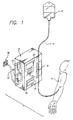
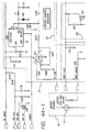
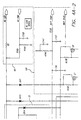
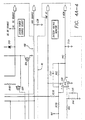
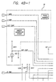
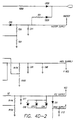
- the invention relates generally to managing a power supply system, and more particularly relates to management of a power supply system having a battery for control over the charging of the battery and the determination of battery status.
- Such a run-time indicator feature is particularly helpful for certain rechargeable batteries, such as nickel-cadmium (“NiCd”) type batteries, which experience an abrupt and severe voltage drop as the stored charge is depleted (as opposed to a more gradual voltage decrease with lead-acid batteries). Such an abrupt voltage drop will result in immediate pump cutoff with no warning.
- the run-time indicator will provide that warning so that the operator knows when to expect the abrupt end of battery power.
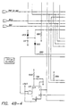
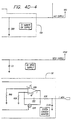
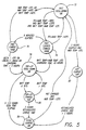
- the first is a fast charge cycle that is applied whenever the battery has undergone the deep discharge operation, whenever the battery has been used for more than approximately fifteen minutes, or if the instrument is left off and unplugged for about twenty-four hours.
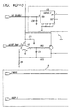
- the charge current is one ampere that is turned on and off during instrument operation to limit heat generation.
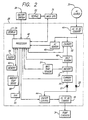
- the battery temperature sensor 51 monitors battery temperature. The end of the fast charge is detected when the temperature of the battery rises to five degrees Celsius ("C") above the ambient temperature as measured by the ambient temperature sensor 58 or when the battery voltage declines by approximately nine millivolts per cell (ninety millivolts total when the battery includes ten cells) below its peak value, or total charge time exceeds four hours.
- C degrees Celsius
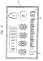
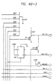
- an "F" icon 60 indicating full charge exists on the front panel 20 of one embodiment of an infusion pump. This icon will not be illuminated after a fast charge cycle.
- the processor 42 stores the capacity for the battery 26 that was entered via the keypad 22 in memory 62.
- the memory 62 also contains various battery-specific rates, such as the rate of capacity decrease due to aging, the rate of charge decrease due to self-discharge, and others.
- the processor monitors the system clock 54, it updates the capacity of the battery based on the elapsed time and based on the stored rates that are specific to a change in battery capacity. For example, after a certain time period, the processor lowers the stored number representative of the battery capacity based on this "aging" of the battery.
- the processor monitors the system clock 54, it updates the stored number representative of the charge in the battery based on the elapsed time and based on the stored rates that are specific to a change in battery charge. For example, after a certain time period, the processor lowers the stored number representative of the battery charge based on this self discharge of the battery.
Landscapes
- Engineering & Computer Science (AREA)
- Power Engineering (AREA)
- Health & Medical Sciences (AREA)
- Heart & Thoracic Surgery (AREA)
- Life Sciences & Earth Sciences (AREA)
- General Physics & Mathematics (AREA)
- Emergency Management (AREA)
- Vascular Medicine (AREA)
- Anesthesiology (AREA)
- Biomedical Technology (AREA)
- Business, Economics & Management (AREA)
- Hematology (AREA)
- Physics & Mathematics (AREA)
- Animal Behavior & Ethology (AREA)
- General Health & Medical Sciences (AREA)
- Public Health (AREA)
- Veterinary Medicine (AREA)
- Charge And Discharge Circuits For Batteries Or The Like (AREA)
- Valve Device For Special Equipments (AREA)
- Earth Drilling (AREA)
- Exchange Systems With Centralized Control (AREA)
- Remote Monitoring And Control Of Power-Distribution Networks (AREA)
- Secondary Cells (AREA)
Claims (31)
- Energieregelungssystem (28) zum Verwalten der Energie zum Betreiben einer biomedizinischen Vorrichtung (10) aus einer wiederaufladbaren Batterie (26) und aus einer externen Energiequelle (30), wobei die biomedizinische Vorrichtung (10) eine Energieforderung für den Betrieb stellt, wobei das System (28) aufweist: eine Verbindungseinrichtung (44, D1, D2) zum Versorgen der biomedizinischen Vorrichtung (10) mit Energie aus einer extemen Energiequelle (30), wenn die Quelle (30) mit dem Energieregelungssystem (28) verbunden ist, und zum Versorgen der biomedizinischen Vorrichtung (10) mit Energie aus der Batterie (26), wenn eine externe Energiequelle (30) nicht mit dem Energieregelungssystem (28) verbunden ist; eine Ladeeinrichtung (52), die mit der Batterie (26) verbunden ist, um der Batterie (26) Ladung in Antwort anf Ladungssteuersignale zuzuführen; einen Prozessor (42), der: ein Ladungsstenersignal an die Ladeeinrichtung (52) gibt, um zu bewirken, daß die Ladeeinrichtung (52) Ladung an die Batterie (26) gibt, wenn eine externe Energiequelle (30) mit dem Energieregelungssystem (88) verbunden ist; automatisch einen Wert für die Ladungsmenge in der Batterie (26) bestimmt; automatisch die Laufzeit der Batterie (26) basierend auf dem bestimmten Wert der Ladungsmenge in der Batterie (6) und der Energieforderung der biomedizinischen Vorrichtung (10) bestimmt; automatisch den bestimmten Wert für die Ladungsmenge in der Batterie anpaßt, basierend auf der Anzahl von Entladungs/Ladungszyklen die die Batterie durchlaufen hat; ein Anzeigesignal bereitstellt, das repräsentativ für die Laufzeit ist; und eine Anzeige (24), die die bestimmte Laufzeit in Antwort auf das Anzeigesignal anzeigt; dadurch gekennzeichnet, daß die Ladeeinrichtung (52) auch mit der Batterie (26) verbunden ist, um die Batterie (26) in Antwort auf Ladungssteuersignale tief zu entladen; und der Prozessor (24) automatisch und periodisch die Ladeeinrichtung (52) steuert, um eine Tiefentladung der Batterie (26) durchzuführen und dann die Batterie (26) voll wieder aufzuladen.
- Energieregelungssystem (28) nach Anspruch 1, bei dem der Prozesor (42) automatisch den Wert für die Ladungsmenge in der Batterie (26) basierend auf der Betriebsweise der biomedizinischen Vorrichtung (10) aus der Batterie (26) absenkt; und automatisch die Laufzeit aktualisiert, um das Absenken des Wertes für die Ladung in der Batterie (26) wiederzugeben.
- Energieregelungssystem (28) nach Anspruch 1 oder Anspruch 2, das weiter aufweist: einen Anzeiger (60) für die volle Ladung, getrennt von der Anzeige (64) für die Laufzeit, welcher angibt, daß die Batterie (26) voll geladen ist; wobei der Prozessor (42) den Anzeiger (60) für die volle Ladung beleuchtet, nachdem das Aufladen der Batterie beendet ist.
- Energieregelungssystem (28) nach einem der vorangehenden Ansprüche, bei dem der Prozessor (42) automatisch die berechnete Kapazität der Batterie (26), um Ladung zu speichern, basierend auf dem Alter der Batterie (26) anpaßt.
- Energieregelungssystem (28) nach einem der vorangehenden Ansprüche, das weiterhin einen Sensor (58) für die Umgebungstemperatur aufweist, welcher ein Umgebungstemperatursignal an den Prozessor (42)gibt, und bei dem der Prozessor (42) einen Wert für die Ladungskapazität der Batterie (26) aufweist; wobei der Prozessor (42) automatisch eine Abnahme in dem Wert für die Kapazität basierend auf dem Umgebungstemperatursignal zur Zeit des Ladens der Batterie (26) berechnet.
- Energieregelungssystem (28) nach einem der vorangehenden Ansprüche, bei dem der Prozessor (42) automatisch eine Abnahme in dem Wert für die Ladungsmenge in der Batterie (26) basierend auf einer vorbestimmten Geschwindigkeit der Selbstentladung der Batterie (26) berechnet.
- Energieregelungssystem (28) nach einem der vorangehenden Ansprüche, bei dem der Prozessor (42) automatisch eine Abnahme in dem Wert für die Ladungsmenge in der Batterie (26) basierend auf einem Fehler beim Beenden eines kompletten Ladungszyklus bestimmt.
- Energieregelungssystem (28) nach einem der vorangehenden Ansprüche, bei dem der Prozessor (42) automatisch einen Zuwachs im Wert für die Ladungsmenge in der Batterie (26) basierend auf der Beendigung eines kompletten Ladungszyklus bestimmt
- Energieregelungssystem (28) nach einem der vorangehenden Ansprüche, bei dem der Prozessor (42) die Ladeeinrichtung (52) steuert, um die Batterie (26) zu laden: in einem Schnellladezyklus, bei dem Ladung auf die Batterie (26) mit einer Geschwindigkeit gegeben wird, die die Schädigung der Batterie hervorrufen wird, wenn nicht der Zyklus zeitlich begrenzt ist; in einem Aufladezyklus anschließend an dem Schnellladezyklus; und in einem Fließladezyklus, in dem Ladung, die aufgrund von Selbstentladung der Batterie (26) verloren geht, ersetzt wird.
- Energieregelungssystem (28) nach Anspruch 9, das weiter aufweist: einen Sensor (58) für die Umgebungstemperatur, welcher ein Umgebungstemperatursignal an den Prozessor (42) gibt; wobei der Prozessor (42) die Ladeeinrichtung (52) steuert, um die Batterie (26) in einem Heißiadezyklus zu laden, wenn das Umgebungstemperatursignal angibt, daß die Umgebungstemperatur einen ersten vorbestimmten Schwellenwert überschreitet, wobei der Heißladezyklus das Aufgeben von Ladung an die Batterie (26) mit einem reduzierten Wert und über eine verlängerte Zeitdauer im Vergleich mit dem Schnellladezyklus aufweist.
- Energieregelungssystem (28) nach Anspruch 10, bei dem der Prozessor (42) automatisch den Heißladezyklus in Antwort auf das Umgebungstemperatursignal aussetzt, welches eine Umgebungstemperatur oberhalb eines zweiten vorbestimmten Schwellenwertes angibt.
- Energieregelungssystem (28) nach einem der vorangehenden Ansprüche, das weiterhin einen Speicher (62) aufweist, in dem der Prozessor (42) automatisch einen Wert für die Ladungskapazität der Batterie speichert und den gespeicherten Wert hält, wenn die Batterie (26) aus der biomedizinischen Vorrichtung (10) entfernt wird.
- Energieregelungssystem (28) nach einem der vorangehenden Ansprüche, das weiter aufweist einen Sensor (49) für die Batteriespannung, der ein Batteriespannungssignal liefert; wobei der Prozessor (42) d Batteriespannungssignal mit einem Schwellenwert für die Spannung vergleicht und einen offen Zustand der Batterie angibt, wenn das Batteriespannungssignal den Schwellenwert überschreitet.
- Energieregelungssystem (28) nach einem der Ansprüche 1 bis 11, das weiter aufweist: einen Sensor (49) für die Batteriespannung, der ein Batteriespannungssignal liefert; einen Speicher (62), in dem Daten gespeichert sind, die zu gespeicherten Ladungswerten zu Batteriespannungen in Bezug stehen; wobei der Prozessor (42) das Batteriespannungssignal und die gespeicherte Ladung mit entsprechend gespeicherten Daten in dem Speicher (42) vergleicht, und wenn das Batteriespannungssignal eine Batteriespannung angibt, die beträchtlich geringer ist als die gespeicherte Batteriespannung, der Prozessor einen Kurzschlußzustand der Batterie angibt.
- Energieregelungssystem (28) nach einem der vorangehenden Ansprüche, das weiter aufweist: einen Speicher (62), in dem Werte für den Stromabzug für verschiedene Betriebsweisen der biomedizinischen Vorrichtung (10) gespeichert sind; wobei der Prozessor (42) die Ladungsmenge bestimmt, die in der Batterie (26) verbleibt, indem die gegenseitige Betriebsweise der biomdizinischen Vorrichtung (10) festgestellt wird, der gespeicherte Stromabzug aus dem Speicher (62) für diese Betriebsweise wiedergewonnen wird und von dem letzten bekannten Ladungswert der Batterie (26) der wiedergewonnene Wert des Stromabzuges über die Betriebszeit subtrahiert wird.
- Energieregelungssystem (28) nach einem der vorangehenden Ansprüche, das weiterhin ein Ladungsindikator (56) ausweist; wobei der Prozessor (42) den Ladungsindikator (56) während der Zeitdauer beleuchtet, wenn die Batterie (26) geladen wird.
- Verfahren zum Verwalten der Energie für eine biomedizinische Vorrichtung (10), die mit einer externen Energiequelle (30) verbindbar ist und die eine interne wiederaufladbare Batterie (26) hat, wobei die biomedizinische Vorrichtung (10) eine Energieforderung für den Betrieb stellt, wobei das Verfahren die Schritte aufweist: Versorgen der biomedizinischen Vorrichtung (10) mit Energie aus der externen Energiequelle (30), wenn die externe Energiequelle (30) angeschlossen ist; Versorgen der biomedizinischen Vorrichtung (10) mit Energie aus der internen Batterie (26), wenn die externe Energiequelle in (30) nicht angeschlossen ist; Wiederaufladen der Batterie (26) auf volle Ladung, wenn die externe Energiequelle (30) angeschlossen ist, automatisches Feststellen der Ladungskapazität der Batterie basierend auf der Anzahl der Entladungs/Ladungszyklen, die die Batterie durchlaufen hat; automatisches Bestimmen eines Wertes für die Ladungsmenge in der Batterie (26) basierend auf der bestimmten Ladungskapazität; automatisches Bestimmen der Laufzeit der Batterie (26) basierend auf dem bestimmten Wert der Ladungsmenge in der Batterie (26) und der Energieforderung der biomedizinischen Vorrichtung (10); und Anzeigen der Länge der Laufzeit für die Batterie (26); gekennzeichnet durch die Schritte des Ladens der Batterie (26) in einem Schnellladezyklus, bei dem die Ladung an die Batterie (26) mit einer Geschwindigkeit gegeben wird, die das Schädigen der Batterie (26) hervorrufen wird, wenn der Zyklus nicht in der Zeit begrenzt ist; Laden der Batterie (26) in einem Aufladezyklus anschließend an den Schnellladezyklus; und Laden der Batterie (26) in einem Fließladezyklus, in dem Ladung, die aufgrund der Selbstentladung der Batterie (26) verloren geht, ersetzt wird.
- Verfahren nach Anspruch 17, das weiter die Schritte aufweist: Automatisches Absenken des Wertes für die Ladungsmenge in der Batterie (26) basierend auf der Betriebsweise der biomedizinischen Vorrichtung (10) aus der Batterie (26); automatisches Aktualisieren der Laufzeit, um die Abnahme des Wertes für die Ladung in der Batterie (26) widerzuspiegeln.
- Verfahren nach Anspruch 17 oder Anspruch 18, das weiter den Schritt des Angebens, getrennt von der Laufzeit, daß die Batterie (26) vollgeladen ist, nachdem das Aufladen der Batterie beendet ist, aufweist.
- Verfahren nach einem der Ansprüche 17 bis 19, das weiterhin den Schritt des automatischen und periodischen Tiefentladens der Batterie (26) und dann des Wiederaufladens der Batterie (26) auf den vollgeladenen Status aufweist.
- Verfahren nach einem der Ansprüche 17 bis 20, das weiter den Schritt des automatischen Berechnens einer Abnahme in dem Wert für die Ladungsmenge in der Batterie (26) basierend auf einer vorbestimmten Rate der Selbstentladung der Batterie (26) aufweist.
- Verfahren nach einer der Ansprüche 17 bis 21, das weiterhin die Schritte aufweist: Zuordnen eines Wertes für die Ladungskapazität der Batterie; und automatisches Bestimmen einer Abnahme in dem Wert für die Kapazität basierend auf der Umgebungstemperatur zur Zeit des Ladens der Batterie (26).
- Verfahren nach einem der Ansprüche 17 bis 22, das weiterhin diesen Schritt des automatischen Absenkens des Wertes für die Ladungsmenge, die in der Batterie (26) gespeichert ist, basierend auf einem Fehler beim Beenden eines vollständigen Ladungszyklus, aufweist.
- Verfahren nach einem der Ansprüche 17 bis 23, das weiterhin den Schritt des automatischen Anhebens des Wertes für die Ladungsmenge, die in der Batterie (26) gespeichert ist, basierend auf dem Abschluß eines vollständigen Ladungszyklus, aufweist
- Verfahren nach einem der Ansprüche 17 bis 24, das weiter die Schritte aufweist: Abfühlen der Umgebungstemperatur (58) und Bereitstellen eines Umgebungstemperatursignals, das die abgefühlte Umgebungstemperatur angibt; Laden der Batterie (26) in einem Heißladezyklus, wenn das Umgebungstemperatursignal angibt, daß die Umgebungstemperatur einen ersten vorbestimmten Schwellenwert überschreitet, wobei der Heißladezyklus das Aufgeben von Ladung an die Batterie (26) mit einem verringertem Wert und über eine erhöhte Zeitdauer im Vergleich zum Schnellladezyklus aufweist
- Verfahren nach Anspruch 25, bei dem Schritt des Ladens in einem Heißladezyklus weiterhin diesen Schritt des automatischen Aussetzens des Heißladezyklus in Antwort auf das Umgebungstemperatursignal umfaßt, das eine Umgebungstemperatur oberhalb eines zweiten vorbestimmten Schwellenwertes angibt.
- Verfahren nach einem der Ansprüche 17 bis 26, das weiterhin den Schritt aufweist: Speichern eines Wertes für die Ladungskapazität der Batterie in einem Speicher (62) und Halten des gespeicherten Wertes, wenn die Batterie (26) aus der biomedizinischen Vorrichtung (10) entfernt wird.
- Verfahren nach einem der Ansprüche 17 bis 27, das weiterhin die Schritte aufweist: Speichern von Werten für den Stromabzug für verschiedene Betriebsweisen der biomedizinischen Vorrichtung (10); Bestimmen der Ladungsmenge, die in der Batterie (26) verbleibt, durch Bestimmen der gegenwärtigen Betriebsweise der biomedizinischen Vorrichtung (10), Wiedergewinnen des gespeicherten Stromabzuges aus dem Speicher (62) für diese Betriebsweise und Subtrahieren des wiedergewonnen Stromabzugswertes über die Zeitdauer der Betriebsweise von dem letzten bekannten Ladungswert der Batterie (26).
- Verfahren nach einem der Ansprüche 17 bis 28, das weiterhin den Schritt des Beleuchtens eines Ladungsindikators (56) während Zeitdauer, wenn die Batterie (26) geladen wird, aufweist.
- Verfahren nach einem der Ansprüche 17 bis 29, das weiterhin die Schritte aufweist: Abfühlen (49) der Spannung der Batterie (26) und Bereitstellen eines Batteriespannungssignals; Vergleichen des Batteriespannungssignals mit einem Schwellenwert für die Spannung und Angeben eines Offen-Zustandes der Batterie, wenn das Batteriespannungssignal den Schwellenwert überschreitet.
- Verfahren nach einem der Ansprüche 17 bis 30, das weiter die Schritte aufweist: Abfühlen (49) der Spannung der Batterie und Bereitstellen eines Batteriespannungssignals; Speichern (62) von Daten, die gespeicherte Ladungswerte zu Batteriespannungen in bezug setzen; V ergleichen des Batteriespannungssignals und der gespeicherten Ladung mit entsprechenden gespeicherten Daten in den Speicher (62), und, falls das Batteriespannungssignal eine Batteriespannung angibt, die beträchtlich geringer ist als die gespeicherte Batteriespannung, Anzeigen eines Kurzschlußzustandes der Batterie.
Priority Applications (1)
| Application Number | Priority Date | Filing Date | Title |
|---|---|---|---|
| EP01125820A EP1215794A3 (de) | 1995-10-02 | 1996-09-27 | Leistungssteuerungssystem |
Applications Claiming Priority (3)
| Application Number | Priority Date | Filing Date | Title |
|---|---|---|---|
| US08/538,096 US5712795A (en) | 1995-10-02 | 1995-10-02 | Power management system |
| US538096 | 1995-10-02 | ||
| PCT/US1996/015526 WO1997013310A1 (en) | 1995-10-02 | 1996-09-27 | Power management system |
Related Child Applications (1)
| Application Number | Title | Priority Date | Filing Date |
|---|---|---|---|
| EP01125820A Division EP1215794A3 (de) | 1995-10-02 | 1996-09-27 | Leistungssteuerungssystem |
Publications (2)
| Publication Number | Publication Date |
|---|---|
| EP0856207A1 EP0856207A1 (de) | 1998-08-05 |
| EP0856207B1 true EP0856207B1 (de) | 2002-05-08 |
Family
ID=24145469
Family Applications (2)
| Application Number | Title | Priority Date | Filing Date |
|---|---|---|---|
| EP96933936A Expired - Lifetime EP0856207B1 (de) | 1995-10-02 | 1996-09-27 | System zur leistungsregelung |
| EP01125820A Withdrawn EP1215794A3 (de) | 1995-10-02 | 1996-09-27 | Leistungssteuerungssystem |
Family Applications After (1)
| Application Number | Title | Priority Date | Filing Date |
|---|---|---|---|
| EP01125820A Withdrawn EP1215794A3 (de) | 1995-10-02 | 1996-09-27 | Leistungssteuerungssystem |
Country Status (8)
| Country | Link |
|---|---|
| US (1) | US5712795A (de) |
| EP (2) | EP0856207B1 (de) |
| JP (1) | JP2000515716A (de) |
| AT (1) | ATE217458T1 (de) |
| DE (2) | DE69621144T2 (de) |
| ES (1) | ES2121713T3 (de) |
| HK (2) | HK1015558A1 (de) |
| WO (1) | WO1997013310A1 (de) |
Families Citing this family (215)
| Publication number | Priority date | Publication date | Assignee | Title |
|---|---|---|---|---|
| US8198900B2 (en) | 1996-07-29 | 2012-06-12 | Midtronics, Inc. | Automotive battery charging system tester |
| US8872517B2 (en) | 1996-07-29 | 2014-10-28 | Midtronics, Inc. | Electronic battery tester with battery age input |
| US6850037B2 (en) | 1997-11-03 | 2005-02-01 | Midtronics, Inc. | In-vehicle battery monitor |
| US6566883B1 (en) * | 1999-11-01 | 2003-05-20 | Midtronics, Inc. | Electronic battery tester |
| US6503221B1 (en) * | 1997-06-12 | 2003-01-07 | Abbott Laboratories | Temperature compensation system for regulating flow through tubing in a pump |
| US8958998B2 (en) * | 1997-11-03 | 2015-02-17 | Midtronics, Inc. | Electronic battery tester with network communication |
| US7705602B2 (en) * | 1997-11-03 | 2010-04-27 | Midtronics, Inc. | Automotive vehicle electrical system diagnostic device |
| US5929601A (en) * | 1997-12-22 | 1999-07-27 | Lifecor, Inc. | Battery management apparatus for portable electronic devices |
| US5896024A (en) * | 1998-03-24 | 1999-04-20 | Black & Decker, Inc. | Method and apparatus for manually selecting battery charging process |
| US5982146A (en) * | 1998-05-15 | 1999-11-09 | Intel Corporation | Method and apparatus for conditioning battery while external power is applied |
| US6194793B1 (en) | 1998-08-07 | 2001-02-27 | Okc Products, Inc. | Apparatus and method for charging an energy storage source |
| US7265494B2 (en) | 1998-10-09 | 2007-09-04 | Azoteq Pty Ltd. | Intelligent user interface with touch sensor technology |
| JP3929243B2 (ja) * | 1998-10-15 | 2007-06-13 | ヤマハ発動機株式会社 | 電動車両用電源システム |
| US6164921A (en) | 1998-11-09 | 2000-12-26 | Moubayed; Ahmad Maher | Curvilinear peristaltic pump having insertable tubing assembly |
| US6172479B1 (en) | 1999-03-04 | 2001-01-09 | Baxter International Inc. | Battery control circuit |
| JP2001057742A (ja) * | 1999-08-11 | 2001-02-27 | Sony Corp | 電子機器の電源装置及び電源制御方法 |
| US6191556B1 (en) | 1999-10-12 | 2001-02-20 | International Business Machines Corporation | Method and apparatus for estimating the service life of a battery |
| US6437574B1 (en) * | 1999-10-26 | 2002-08-20 | Adtran, Inc. | Auxiliary battery test and alarm system for telecommunication equipment |
| EP1100172A3 (de) * | 1999-11-10 | 2004-10-13 | Makita Corporation | Batterieladevorrichtung |
| US6348777B1 (en) | 2000-02-29 | 2002-02-19 | Alaris Medical Systems, Inc. | Power management system |
| US6366053B1 (en) * | 2000-03-01 | 2002-04-02 | Metropolitan Industries, Inc. | DC pump control system |
| JP2001246821A (ja) * | 2000-03-07 | 2001-09-11 | Sony Corp | プリンターと一体化した各種機器 |
| US8513949B2 (en) * | 2000-03-27 | 2013-08-20 | Midtronics, Inc. | Electronic battery tester or charger with databus connection |
| US7398176B2 (en) * | 2000-03-27 | 2008-07-08 | Midtronics, Inc. | Battery testers with secondary functionality |
| US7446536B2 (en) | 2000-03-27 | 2008-11-04 | Midtronics, Inc. | Scan tool for electronic battery tester |
| JP4875235B2 (ja) * | 2000-04-03 | 2012-02-15 | レノボ シンガポール プライヴェート リミテッド | 電源装置、電源容量情報補正装置、電源容量情報補正方法及びコンピュータ |
| EP1290652A2 (de) | 2000-05-05 | 2003-03-12 | Hill-Rom Services, Inc. | Krankenhausüberwachungsverfahren und vorrichtung |
| BR0110596A (pt) | 2000-05-05 | 2005-08-02 | Hill Rom Services Inc | Sistema de monitoramento de paciente, sistema de computador, sistema para monitorar informação de paciente, aparelho de assistência ao paciente, aparelho de andador, aparelho de assistência ao paciente, e, mostrador para um computador |
| US6522103B1 (en) * | 2000-08-22 | 2003-02-18 | Hitachi, Ltd. | Sodium-sulphur battery system and driving method thereof |
| JP2002199588A (ja) * | 2000-12-27 | 2002-07-12 | Hitachi Ltd | 電源システム |
| US6449203B1 (en) * | 2001-03-08 | 2002-09-10 | Micron Technology, Inc. | Refresh controller and address remapping circuit and method for dual mode full/reduced density DRAMs |
| US20020138772A1 (en) * | 2001-03-22 | 2002-09-26 | Crawford Timothy James | Battery management system employing software controls upon power failure to estimate battery duration based on battery/equipment profiles and real-time battery usage |
| WO2002080126A2 (en) | 2001-03-30 | 2002-10-10 | Hill-Rom Services, Inc. | Hospital bed and network system |
| US7205746B2 (en) * | 2001-04-06 | 2007-04-17 | Microchip Technology Inc. | Battery cover assembly having integrated battery condition monitoring |
| EP1815879A3 (de) | 2001-05-18 | 2007-11-14 | Deka Products Limited Partnership | Infusionsset für eine Flüssigkeitspumpe |
| US8034026B2 (en) * | 2001-05-18 | 2011-10-11 | Deka Products Limited Partnership | Infusion pump assembly |
| US6751159B2 (en) * | 2001-10-26 | 2004-06-15 | Micron Technology, Inc. | Memory device operable in either a high-power, full-page size mode or a low-power, reduced-page size mode |
| DE20119187U1 (de) * | 2001-11-27 | 2002-04-18 | Witte & Sutor Gmbh | Otoskop |
| US7054233B2 (en) * | 2001-11-30 | 2006-05-30 | Equity Industries, Inc. | Wall clock with dial illumination |
| US6985870B2 (en) | 2002-01-11 | 2006-01-10 | Baxter International Inc. | Medication delivery system |
| US20030204419A1 (en) * | 2002-04-30 | 2003-10-30 | Wilkes Gordon J. | Automated messaging center system and method for use with a healthcare system |
| US6838331B2 (en) | 2002-04-09 | 2005-01-04 | Micron Technology, Inc. | Method and system for dynamically operating memory in a power-saving error correction mode |
| US6751143B2 (en) * | 2002-04-11 | 2004-06-15 | Micron Technology, Inc. | Method and system for low power refresh of dynamic random access memories |
| US20030201697A1 (en) * | 2002-04-30 | 2003-10-30 | Richardson William R. | Storage device for health care facility |
| US20040012265A1 (en) * | 2002-05-23 | 2004-01-22 | International Business Machines Corporation | System and method to control redundant power supplies selection |
| US20030225596A1 (en) * | 2002-05-31 | 2003-12-04 | Richardson Bill R. | Biometric security for access to a storage device for a healthcare facility |
| US20040119341A1 (en) * | 2002-09-16 | 2004-06-24 | Hickle Randall S. | Battery backup method and system |
| DE10256545A1 (de) * | 2002-12-04 | 2004-06-24 | Hilti Ag | Ladeverfahren für Akkumulatorenpacks |
| JP4698117B2 (ja) * | 2002-12-16 | 2011-06-08 | 株式会社ユニバーサルエンターテインメント | 情報提供装置 |
| US7399205B2 (en) | 2003-08-21 | 2008-07-15 | Hill-Rom Services, Inc. | Plug and receptacle having wired and wireless coupling |
| US7154276B2 (en) * | 2003-09-05 | 2006-12-26 | Midtronics, Inc. | Method and apparatus for measuring a parameter of a vehicle electrical system |
| US8164343B2 (en) | 2003-09-05 | 2012-04-24 | Midtronics, Inc. | Method and apparatus for measuring a parameter of a vehicle electrical system |
| US9018958B2 (en) | 2003-09-05 | 2015-04-28 | Midtronics, Inc. | Method and apparatus for measuring a parameter of a vehicle electrical system |
| US9255955B2 (en) | 2003-09-05 | 2016-02-09 | Midtronics, Inc. | Method and apparatus for measuring a parameter of a vehicle electrical system |
| US8540493B2 (en) | 2003-12-08 | 2013-09-24 | Sta-Rite Industries, Llc | Pump control system and method |
| US7319386B2 (en) | 2004-08-02 | 2008-01-15 | Hill-Rom Services, Inc. | Configurable system for alerting caregivers |
| US8344685B2 (en) * | 2004-08-20 | 2013-01-01 | Midtronics, Inc. | System for automatically gathering battery information |
| US9496720B2 (en) | 2004-08-20 | 2016-11-15 | Midtronics, Inc. | System for automatically gathering battery information |
| US8436619B2 (en) * | 2004-08-20 | 2013-05-07 | Midtronics, Inc. | Integrated tag reader and environment sensor |
| US8442877B2 (en) | 2004-08-20 | 2013-05-14 | Midtronics, Inc. | Simplification of inventory management |
| US7686589B2 (en) | 2004-08-26 | 2010-03-30 | Pentair Water Pool And Spa, Inc. | Pumping system with power optimization |
| US8480373B2 (en) | 2004-08-26 | 2013-07-09 | Pentair Water Pool And Spa, Inc. | Filter loading |
| US8602745B2 (en) | 2004-08-26 | 2013-12-10 | Pentair Water Pool And Spa, Inc. | Anti-entrapment and anti-dead head function |
| US7874808B2 (en) | 2004-08-26 | 2011-01-25 | Pentair Water Pool And Spa, Inc. | Variable speed pumping system and method |
| US8043070B2 (en) | 2004-08-26 | 2011-10-25 | Pentair Water Pool And Spa, Inc. | Speed control |
| US8469675B2 (en) | 2004-08-26 | 2013-06-25 | Pentair Water Pool And Spa, Inc. | Priming protection |
| US8019479B2 (en) | 2004-08-26 | 2011-09-13 | Pentair Water Pool And Spa, Inc. | Control algorithm of variable speed pumping system |
| US7845913B2 (en) | 2004-08-26 | 2010-12-07 | Pentair Water Pool And Spa, Inc. | Flow control |
| US20060168916A1 (en) * | 2004-11-05 | 2006-08-03 | Griebel Robert A E | Method and apparatus to insert stoppers into prefilled syringes |
| JP4318044B2 (ja) * | 2005-03-03 | 2009-08-19 | ソニー株式会社 | 電力供給システム、電力供給装置および方法、受電装置および方法、記録媒体、並びにプログラム |
| US20070264130A1 (en) * | 2006-01-27 | 2007-11-15 | Phluid, Inc. | Infusion Pumps and Methods for Use |
| KR101380748B1 (ko) * | 2006-10-10 | 2014-04-02 | 삼성전자 주식회사 | 사용자 선택에 따라 배터리 충전모드를 변경하는컴퓨터시스템 및 그 제어방법 |
| BRPI0719107A2 (pt) * | 2006-11-21 | 2013-12-03 | Baxter Int | Sistema e método par monitoramento remoto e/ou manipulação de terapias de infusão |
| US8390244B2 (en) * | 2007-03-30 | 2013-03-05 | Nipro Healthcare Systems, Llc | Rechargeable battery backup apparatus and method for insulin pump |
| US20080269729A1 (en) * | 2007-04-26 | 2008-10-30 | Carl Zeiss Meditec Ag | Uninterrupted power supply, especially for a refractive laser |
| FR2916099B1 (fr) * | 2007-05-11 | 2009-07-31 | Commissariat Energie Atomique | Procede de charge d'une batterie d'un systeme autonome |
| JP5117108B2 (ja) * | 2007-05-24 | 2013-01-09 | 太平洋工業株式会社 | 電気機器及びタイヤ状態監視装置 |
| GB2491304B (en) * | 2007-07-17 | 2013-01-09 | Midtronics Inc | Battery tester and electric vehicle |
| US9274157B2 (en) * | 2007-07-17 | 2016-03-01 | Midtronics, Inc. | Battery tester for electric vehicle |
| US8287514B2 (en) | 2007-09-07 | 2012-10-16 | Asante Solutions, Inc. | Power management techniques for an infusion pump system |
| US8082160B2 (en) * | 2007-10-26 | 2011-12-20 | Hill-Rom Services, Inc. | System and method for collection and communication of data from multiple patient care devices |
| CN101515023A (zh) * | 2007-12-06 | 2009-08-26 | 密特电子公司 | 蓄电池和电池测试器 |
| US9026370B2 (en) | 2007-12-18 | 2015-05-05 | Hospira, Inc. | User interface improvements for medical devices |
| US8986253B2 (en) * | 2008-01-25 | 2015-03-24 | Tandem Diabetes Care, Inc. | Two chamber pumps and related methods |
| ATE494026T1 (de) | 2008-03-10 | 2011-01-15 | Hoffmann La Roche | Medizinische vorrichtung und ladestation dafür |
| US8579600B2 (en) | 2008-03-28 | 2013-11-12 | Sta-Rite Industries, Llc | System and method for portable battery back-up sump pump |
| US20110087197A1 (en) * | 2008-04-21 | 2011-04-14 | Bruno Mombrinie | Antegrade colonic instillation apparatus |
| US20090287180A1 (en) * | 2008-05-19 | 2009-11-19 | Diperna Paul M | Disposable pump reservoir and related methods |
| CN104971416B (zh) | 2008-09-10 | 2018-05-01 | 瑞思迈有限公司 | 呼吸治疗设备中改进的功率管理 |
| US8408421B2 (en) | 2008-09-16 | 2013-04-02 | Tandem Diabetes Care, Inc. | Flow regulating stopcocks and related methods |
| CA2737461A1 (en) * | 2008-09-19 | 2010-03-25 | Tandem Diabetes Care, Inc. | Solute concentration measurement device and related methods |
| MX2011003708A (es) | 2008-10-06 | 2011-06-16 | Pentair Water Pool & Spa Inc | Metodo para operar un sistema de seguridad para alivio de vacio. |
| US8016789B2 (en) | 2008-10-10 | 2011-09-13 | Deka Products Limited Partnership | Pump assembly with a removable cover assembly |
| US8262616B2 (en) | 2008-10-10 | 2012-09-11 | Deka Products Limited Partnership | Infusion pump assembly |
| US8708376B2 (en) | 2008-10-10 | 2014-04-29 | Deka Products Limited Partnership | Medium connector |
| US8267892B2 (en) | 2008-10-10 | 2012-09-18 | Deka Products Limited Partnership | Multi-language / multi-processor infusion pump assembly |
| US8223028B2 (en) | 2008-10-10 | 2012-07-17 | Deka Products Limited Partnership | Occlusion detection system and method |
| US8066672B2 (en) * | 2008-10-10 | 2011-11-29 | Deka Products Limited Partnership | Infusion pump assembly with a backup power supply |
| US9180245B2 (en) | 2008-10-10 | 2015-11-10 | Deka Products Limited Partnership | System and method for administering an infusible fluid |
| US8405346B2 (en) * | 2009-02-17 | 2013-03-26 | Diversified Power International, Llc | Inductively coupled power transfer assembly |
| US8564233B2 (en) | 2009-06-09 | 2013-10-22 | Sta-Rite Industries, Llc | Safety system and method for pump and motor |
| US9556874B2 (en) | 2009-06-09 | 2017-01-31 | Pentair Flow Technologies, Llc | Method of controlling a pump and motor |
| EP2459251B1 (de) | 2009-07-30 | 2014-03-12 | Tandem Diabetes Care, Inc. | Infusionspumpensystem mit einwegkartusche mit druckentlüftung und druckfeedback |
| CN102576895B (zh) * | 2009-09-24 | 2014-08-27 | 丰田自动车株式会社 | 二次电池的制造方法 |
| US9588185B2 (en) | 2010-02-25 | 2017-03-07 | Keith S. Champlin | Method and apparatus for detecting cell deterioration in an electrochemical cell or battery |
| US9425487B2 (en) | 2010-03-03 | 2016-08-23 | Midtronics, Inc. | Monitor for front terminal batteries |
| US8612055B2 (en) * | 2010-04-16 | 2013-12-17 | Medtronic, Inc. | System and method for delivering a therapeutic agent according to default infusion schedule |
| US9229062B2 (en) | 2010-05-27 | 2016-01-05 | Midtronics, Inc. | Electronic storage battery diagnostic system |
| US10046649B2 (en) | 2012-06-28 | 2018-08-14 | Midtronics, Inc. | Hybrid and electric vehicle battery pack maintenance device |
| DE112011101892T5 (de) | 2010-06-03 | 2013-03-21 | Midtronics, Inc. | Akku-Satz-Wartung für elektrische Fahrzeuge |
| US11740294B2 (en) | 2010-06-03 | 2023-08-29 | Midtronics, Inc. | High use battery pack maintenance |
| US8738309B2 (en) | 2010-09-30 | 2014-05-27 | Midtronics, Inc. | Battery pack maintenance for electric vehicles |
| US9419311B2 (en) | 2010-06-18 | 2016-08-16 | Midtronics, Inc. | Battery maintenance device with thermal buffer |
| US9201120B2 (en) | 2010-08-12 | 2015-12-01 | Midtronics, Inc. | Electronic battery tester for testing storage battery |
| CA2820887C (en) | 2010-12-08 | 2019-10-22 | Pentair Water Pool And Spa, Inc. | Discharge vacuum relief valve for safety vacuum release system |
| TWI481148B (zh) * | 2010-12-09 | 2015-04-11 | Compal Electronics Inc | 電池充電控制方法與電子裝置 |
| US8888743B2 (en) * | 2010-12-13 | 2014-11-18 | Baxter International Inc. | Battery management system |
| EP2662949A4 (de) * | 2011-01-06 | 2017-04-19 | Nec Corporation | Ladesteuervorrichtung, ladesteuerverfahren und programm dafür |
| US8852152B2 (en) | 2011-02-09 | 2014-10-07 | Asante Solutions, Inc. | Infusion pump systems and methods |
| US8450969B2 (en) | 2011-02-28 | 2013-05-28 | Toyota Motor Engineering & Manufacturing North America, Inc. | System for automatically charging electrically powered automated guided vehicles |
| US8606424B2 (en) * | 2011-04-05 | 2013-12-10 | King Fahd University Of Petroleum And Minerals | Particle swarm optimization system and method for microgrids |
| US9940440B2 (en) | 2011-04-28 | 2018-04-10 | Medtronic, Inc. | Detecting and responding to software and hardware anomalies in a fluid delivery system |
| US20130043840A1 (en) * | 2011-08-16 | 2013-02-21 | GM Global Technology Operations LLC | Systems and methods for performing cell balancing in a vehicle using cell capacities |
| WO2013028497A1 (en) | 2011-08-19 | 2013-02-28 | Hospira, Inc. | Systems and methods for a graphical interface including a graphical representation of medical data |
| JP6176113B2 (ja) * | 2011-09-02 | 2017-08-09 | 日本電気株式会社 | 電池制御システム、電池制御装置、電池制御方法、およびプログラム |
| US20130093385A1 (en) * | 2011-10-14 | 2013-04-18 | Research In Motion Limited | Mode changing power control |
| US10429449B2 (en) | 2011-11-10 | 2019-10-01 | Midtronics, Inc. | Battery pack tester |
| WO2013090709A1 (en) | 2011-12-16 | 2013-06-20 | Hospira, Inc. | System for monitoring and delivering medication to a patient and method of using the same to minimize the risks associated with automated therapy |
| ES2741725T3 (es) | 2012-03-30 | 2020-02-12 | Icu Medical Inc | Sistema de detección de aire y método para detectar aire en una bomba de un sistema de infusión |
| US9180242B2 (en) | 2012-05-17 | 2015-11-10 | Tandem Diabetes Care, Inc. | Methods and devices for multiple fluid transfer |
| US11325479B2 (en) | 2012-06-28 | 2022-05-10 | Midtronics, Inc. | Hybrid and electric vehicle battery maintenance device |
| US9851411B2 (en) | 2012-06-28 | 2017-12-26 | Keith S. Champlin | Suppressing HF cable oscillations during dynamic measurements of cells and batteries |
| US10463788B2 (en) | 2012-07-31 | 2019-11-05 | Icu Medical, Inc. | Patient care system for critical medications |
| US9383244B2 (en) | 2012-10-25 | 2016-07-05 | Pentair Flow Technologies, Llc | Fluid level sensor systems and methods |
| US9638193B2 (en) | 2012-10-25 | 2017-05-02 | Pentair Flow Technologies, Llc | Sump pump remote monitoring systems and methods |
| US9885360B2 (en) | 2012-10-25 | 2018-02-06 | Pentair Flow Technologies, Llc | Battery backup sump pump systems and methods |
| US10121533B2 (en) | 2012-11-21 | 2018-11-06 | Nano-Retina, Inc. | Techniques for data retention in memory cells during power interruption |
| US9720477B2 (en) * | 2012-11-21 | 2017-08-01 | Nano-Retina, Inc. | Weak power supply operation and control |
| JP5954144B2 (ja) * | 2012-11-30 | 2016-07-20 | ソニー株式会社 | 制御装置、制御方法、制御システムおよび電動車両 |
| KR101428293B1 (ko) * | 2012-12-18 | 2014-08-07 | 현대자동차주식회사 | 전기자동차용 보조배터리의 주기적 충전 방법 |
| TWI465939B (zh) * | 2013-01-07 | 2014-12-21 | Univ Lunghwa Sci & Technology | A Multi - stage Fast Charge Method for Optimizing Lithium Batteries |
| US9173998B2 (en) | 2013-03-14 | 2015-11-03 | Tandem Diabetes Care, Inc. | System and method for detecting occlusions in an infusion pump |
| CN105164920B (zh) | 2013-03-15 | 2018-02-06 | 艾尔弗雷德·E·曼科学研究基金会 | 具有快速开启时间的电流感测多输出电流刺激器 |
| US9244100B2 (en) | 2013-03-15 | 2016-01-26 | Midtronics, Inc. | Current clamp with jaw closure detection |
| US9312575B2 (en) | 2013-05-16 | 2016-04-12 | Midtronics, Inc. | Battery testing system and method |
| US10046112B2 (en) | 2013-05-24 | 2018-08-14 | Icu Medical, Inc. | Multi-sensor infusion system for detecting air or an occlusion in the infusion system |
| AU2014274146B2 (en) | 2013-05-29 | 2019-01-24 | Icu Medical, Inc. | Infusion system which utilizes one or more sensors and additional information to make an air determination regarding the infusion system |
| EP3003442B1 (de) | 2013-05-29 | 2020-12-30 | ICU Medical, Inc. | Infusionssystem und verfahren zur verwendung zur verhinderung der übersättigung eines analog-digital-wandlers |
| AU2014296323B2 (en) | 2013-07-29 | 2019-04-04 | Alfred E. Mann Foundation For Scientific Research | Microprocessor controlled class E driver |
| US10843574B2 (en) | 2013-12-12 | 2020-11-24 | Midtronics, Inc. | Calibration and programming of in-vehicle battery sensors |
| US9923289B2 (en) | 2014-01-16 | 2018-03-20 | Midtronics, Inc. | Battery clamp with endoskeleton design |
| US9333291B2 (en) | 2014-01-16 | 2016-05-10 | Hospira, Inc. | Infusion pump battery capacity management and battery charge alert system and method |
| EP3110317B1 (de) | 2014-02-25 | 2023-05-03 | ICU Medical, Inc. | Patientenüberwachungssystem mit gatekeeper-signal und entsprechendes verfahren |
| ES2776363T3 (es) | 2014-02-28 | 2020-07-30 | Icu Medical Inc | Sistema de infusión y método que utiliza detección óptica de aire en línea de doble longitud de onda |
| TWI681691B (zh) | 2014-04-30 | 2020-01-01 | 瑞士商菲利浦莫里斯製品股份有限公司 | 電熱式氣溶膠產生系統、裝置及其控制方法 |
| US10383059B2 (en) * | 2014-05-23 | 2019-08-13 | General Motors Llc | Vehicle telematics unit power management |
| WO2015184366A1 (en) | 2014-05-29 | 2015-12-03 | Hospira, Inc. | Infusion system and pump with configurable closed loop delivery rate catch-up |
| CN112838286A (zh) * | 2014-06-30 | 2021-05-25 | 赛尔格有限责任公司 | 电池中区分短路的系统和方法 |
| US10473555B2 (en) | 2014-07-14 | 2019-11-12 | Midtronics, Inc. | Automotive maintenance system |
| EP3180071B1 (de) | 2014-08-15 | 2021-09-22 | Axonics, Inc. | Externe impulsgeneratorvorrichtung und zugehörige system zur versuchsnervenstimulation |
| US9555246B2 (en) | 2014-08-15 | 2017-01-31 | Axonics Modulation Technologies, Inc. | Electromyographic lead positioning and stimulation titration in a nerve stimulation system for treatment of overactive bladder |
| CN106659882A (zh) | 2014-08-15 | 2017-05-10 | 艾克索尼克斯调制技术股份有限公司 | 用于进行神经刺激以减轻膀胱功能障碍和其他适应症的可植入引线附着结构 |
| US9855423B2 (en) | 2014-08-15 | 2018-01-02 | Axonics Modulation Technologies, Inc. | Systems and methods for neurostimulation electrode configurations based on neural localization |
| AU2015301402B2 (en) | 2014-08-15 | 2020-06-04 | Axonics Modulation Technologies, Inc. | Integrated electromyographic clinician programmer for use with an implantable neurostimulator |
| US10222397B2 (en) | 2014-09-26 | 2019-03-05 | Midtronics, Inc. | Cable connector for electronic battery tester |
| US11344668B2 (en) | 2014-12-19 | 2022-05-31 | Icu Medical, Inc. | Infusion system with concurrent TPN/insulin infusion |
| CN107427683B (zh) | 2015-01-09 | 2019-06-21 | 艾克索尼克斯调制技术股份有限公司 | 用于可植入神经刺激器的改进天线和使用方法 |
| CN107427685B (zh) | 2015-01-09 | 2021-09-21 | 艾克索尼克斯股份有限公司 | 与神经刺激充电设备一起使用的附接设备及相关联方法 |
| EP3242712B1 (de) | 2015-01-09 | 2019-04-10 | Axonics Modulation Technologies, Inc. | Patientenfernbedienung und zugehörige verfahren zur verwendung mit einem nervenstimulationssystem |
| JP2016133006A (ja) * | 2015-01-16 | 2016-07-25 | セイコーエプソン株式会社 | 液体輸送装置及び液体輸送方法 |
| US10317468B2 (en) | 2015-01-26 | 2019-06-11 | Midtronics, Inc. | Alternator tester |
| US10850024B2 (en) | 2015-03-02 | 2020-12-01 | Icu Medical, Inc. | Infusion system, device, and method having advanced infusion features |
| EP3297697B1 (de) | 2015-05-18 | 2022-05-11 | Smith & Nephew plc | Unterdruckwundtherapievorrichtung |
| CN107847731B (zh) | 2015-07-10 | 2019-06-28 | 艾克索尼克斯调制技术股份有限公司 | 具有无asic的内部电子设备的可植入神经刺激器以及使用方法 |
| CA2995469C (en) | 2015-08-13 | 2023-10-03 | Smith & Nephew, Inc. | Systems and methods for applying reduced pressure therapy |
| US9806544B2 (en) * | 2015-08-14 | 2017-10-31 | Draeger Medical Systems, Inc. | Medical device battery charge indicator |
| US9966676B2 (en) | 2015-09-28 | 2018-05-08 | Midtronics, Inc. | Kelvin connector adapter for storage battery |
| AU2016341195B2 (en) | 2015-10-19 | 2019-03-14 | Icu Medical, Inc. | Hemodynamic monitoring system with detachable display unit |
| US10492141B2 (en) * | 2015-11-17 | 2019-11-26 | Tandem Diabetes Care, Inc. | Methods for reduction of battery usage in ambulatory infusion pumps |
| FR3046706B1 (fr) * | 2016-01-07 | 2018-02-16 | Commissariat A L'energie Atomique Et Aux Energies Alternatives | Procede et dispositif de charge d'une batterie |
| ES2862303T3 (es) | 2016-01-29 | 2021-10-07 | Axonics Modulation Tech Inc | Sistemas de ajuste de frecuencia para optimizar la carga de un neuroestimulador implantable |
| CN108697897B (zh) | 2016-02-12 | 2023-01-13 | 艾克索尼克斯股份有限公司 | 用于试验神经刺激的外部脉冲发生器设备和相关联方法 |
| US10360787B2 (en) | 2016-05-05 | 2019-07-23 | Hill-Rom Services, Inc. | Discriminating patient care communications system |
| EP4085944A1 (de) | 2016-05-13 | 2022-11-09 | ICU Medical, Inc. | Infusionspumpensystem mit gemeinsamer leitung zur automatischen spülung |
| WO2017214441A1 (en) | 2016-06-10 | 2017-12-14 | Icu Medical, Inc. | Acoustic flow sensor for continuous medication flow measurements and feedback control of infusion |
| US10608353B2 (en) | 2016-06-28 | 2020-03-31 | Midtronics, Inc. | Battery clamp |
| CN106207295A (zh) * | 2016-08-19 | 2016-12-07 | 北汽福田汽车股份有限公司 | 用于电池系统的充电方法、电池系统和车辆 |
| KR101987528B1 (ko) * | 2016-09-26 | 2019-06-10 | 현대자동차주식회사 | 자동차의 배터리 관리 시스템 및 방법 |
| US11054480B2 (en) | 2016-10-25 | 2021-07-06 | Midtronics, Inc. | Electrical load for electronic battery tester and electronic battery tester including such electrical load |
| WO2018150263A1 (en) | 2017-02-15 | 2018-08-23 | Smith & Nephew Pte. Limited | Negative pressure wound therapy apparatuses and methods for using the same |
| WO2019063467A1 (en) | 2017-09-29 | 2019-04-04 | T.J.Smith And Nephew,Limited | APPARATUS FOR TREATING NEGATIVE PRESSURE WAVES WITH REMOVABLE PANELS |
| US10089055B1 (en) | 2017-12-27 | 2018-10-02 | Icu Medical, Inc. | Synchronized display of screen content on networked devices |
| GB201813282D0 (en) | 2018-08-15 | 2018-09-26 | Smith & Nephew | System for medical device activation and opertion |
| AU2019224043A1 (en) | 2018-02-22 | 2020-08-20 | Axonics, Inc. | Neurostimulation leads for trial nerve stimulation and methods of use |
| GB201804347D0 (en) | 2018-03-19 | 2018-05-02 | Smith & Nephew Inc | Securing control of settings of negative pressure wound therapy apparatuses and methods for using the same |
| USD888225S1 (en) | 2018-04-30 | 2020-06-23 | Smith & Nephew Asia Pacific Pte. Limited | Pump and canister assembly for negative pressure wound therapy |
| GB201806988D0 (en) | 2018-04-30 | 2018-06-13 | Quintanar Felix Clarence | Power source charging for negative pressure wound therapy apparatus |
| US11559619B2 (en) | 2018-04-30 | 2023-01-24 | Smith & Nephew Asia Pacific Pte. Limited | Systems and methods for controlling dual mode negative pressure wound therapy apparatus |
| JP7140540B2 (ja) * | 2018-05-07 | 2022-09-21 | キヤノン株式会社 | 電子機器、および電子機器の制御方法、プログラム、記憶媒体 |
| GB201808438D0 (en) | 2018-05-23 | 2018-07-11 | Smith & Nephew | Systems and methods for determining blockages in a negative pressure wound therapy system |
| US11513160B2 (en) | 2018-11-29 | 2022-11-29 | Midtronics, Inc. | Vehicle battery maintenance device |
| US11642537B2 (en) | 2019-03-11 | 2023-05-09 | Axonics, Inc. | Charging device with off-center coil |
| US11439829B2 (en) | 2019-05-24 | 2022-09-13 | Axonics, Inc. | Clinician programmer methods and systems for maintaining target operating temperatures |
| WO2020242900A1 (en) | 2019-05-24 | 2020-12-03 | Axonics Modulation Technologies, Inc. | Trainer device for a neurostimulator programmer and associated methods of use with a neurostimulation system |
| US11566972B2 (en) | 2019-07-31 | 2023-01-31 | Midtronics, Inc. | Tire tread gauge using visual indicator |
| US11545839B2 (en) | 2019-11-05 | 2023-01-03 | Midtronics, Inc. | System for charging a series of connected batteries |
| US11668779B2 (en) | 2019-11-11 | 2023-06-06 | Midtronics, Inc. | Hybrid and electric vehicle battery pack maintenance device |
| US11474153B2 (en) | 2019-11-12 | 2022-10-18 | Midtronics, Inc. | Battery pack maintenance system |
| US11278671B2 (en) | 2019-12-04 | 2022-03-22 | Icu Medical, Inc. | Infusion pump with safety sequence keypad |
| US11973202B2 (en) | 2019-12-31 | 2024-04-30 | Midtronics, Inc. | Intelligent module interface for battery maintenance device |
| US11486930B2 (en) | 2020-01-23 | 2022-11-01 | Midtronics, Inc. | Electronic battery tester with battery clamp storage holsters |
| CA3189781A1 (en) | 2020-07-21 | 2022-01-27 | Icu Medical, Inc. | Fluid transfer devices and methods of use |
| CN112234265A (zh) * | 2020-08-31 | 2021-01-15 | 国网福建省电力有限公司 | 一种无人机电池智能充电管理系统 |
| US11135360B1 (en) | 2020-12-07 | 2021-10-05 | Icu Medical, Inc. | Concurrent infusion with common line auto flush |
| CA3224037A1 (en) * | 2021-07-12 | 2023-01-19 | Baxter International Inc. | Systems for multi-level thermal management of electronic devices |
Family Cites Families (26)
| Publication number | Priority date | Publication date | Assignee | Title |
|---|---|---|---|---|
| US3925772A (en) * | 1974-06-27 | 1975-12-09 | Com Tel Inc | A.C. power supply circuit in combination with an A.C. source and a D.C. source |
| CH648936A5 (en) * | 1980-12-31 | 1985-04-15 | Helmut Koechler | Method for monitoring the discharge characteristic of a galvanic element and device for carrying out the method |
| US4468571A (en) * | 1982-10-27 | 1984-08-28 | Saft America, Inc. | Standby power system |
| US4673826A (en) * | 1984-12-20 | 1987-06-16 | The United States Of America As Represented By The Secretary Of The Air Force | Autonomous uninterruptable power supply apparatus |
| US4845419A (en) * | 1985-11-12 | 1989-07-04 | Norand Corporation | Automatic control means providing a low-power responsive signal, particularly for initiating data preservation operation |
| DE3625905A1 (de) * | 1986-01-14 | 1987-07-23 | Eikoh Giken Co Ltd | Schaltungsanordnung zum pruefen der lebensdauer einer batterie |
| US4782241A (en) * | 1987-08-11 | 1988-11-01 | Liebert Corporation | Uninterruptible power supply apparatus and power path transfer method |
| US4820966A (en) * | 1988-06-13 | 1989-04-11 | Ron Fridman | Battery monitoring system |
| US5019717A (en) * | 1988-11-14 | 1991-05-28 | Elegant Design Solutions Inc. | Computer-controlled uninterruptable power supply |
| US4876513A (en) * | 1988-12-05 | 1989-10-24 | Globe-Union Inc. | Dynamic state-of-charge indicator for a battery and method thereof |
| US5148043A (en) * | 1989-07-25 | 1992-09-15 | Kabushiki Kaisha Toshiba | Uninterruptible power supply diagnosing remaining battery capacity during normal external power source operation |
| US4952862A (en) * | 1989-09-29 | 1990-08-28 | At&T Bell Laboratories | Apparatus and method for adaptively predicting battery discharge reserve time |
| US5117324A (en) * | 1989-11-13 | 1992-05-26 | Exide Electronics | Ups-computer system and method for initiating computer shutdown based on remaining battery time as determined from sensed battery voltage and discharge curves |
| US5057697A (en) * | 1990-03-22 | 1991-10-15 | The United States Of America As Represented By The Secretary Of The Navy | DC uninterrupted power supply having instantaneous switching followed by low impedance switching |
| EP0458232A3 (en) * | 1990-05-25 | 1992-05-20 | Abb Ceag Licht- Und Stromversorgungstechnik Gmbh | Control- and measurement device for mobile battery powered equipment |
| CA2038160C (en) * | 1991-03-13 | 1996-10-22 | Jiri K. Nor | Charging circuits for rechargeable batteries and cells |
| US5182518A (en) * | 1991-04-11 | 1993-01-26 | Best Power Technology, Inc. | Inverter and battery testing for uninterruptible power systems |
| US5315533A (en) * | 1991-05-17 | 1994-05-24 | Best Power Technology, Inc. | Back-up uninterruptible power system |
| US5321392A (en) * | 1991-10-18 | 1994-06-14 | Baxter International Inc. | Infusion pump with battery back-up |
| ATE179034T1 (de) * | 1991-10-30 | 1999-04-15 | Texas Instruments Inc | Verbesserungen für batterien und batteriesysteme |
| EP0539640A1 (de) * | 1991-10-30 | 1993-05-05 | Texas Instruments Limited | Batterieverbesserungen |
| US5475294A (en) * | 1991-12-27 | 1995-12-12 | Nippon Densan Corporation | Charge controller for battery charger |
| US5440221A (en) * | 1992-07-08 | 1995-08-08 | Benchmarg Microelectronics, Inc. | Method and apparatus for monitoring batttery capacity with charge control |
| FR2694637B1 (fr) * | 1992-08-05 | 1994-10-07 | Merlin Gerin | Procédé de détermination du temps d'autonomie d'une batterie. |
| US5347164A (en) * | 1992-10-08 | 1994-09-13 | Accton Technology Corporation | Uninterruptible power supply having a 115V or 230V selectable AC output and power saving |
| US5545969A (en) * | 1992-12-02 | 1996-08-13 | Matsushita Electric Industrial Co., Ltd. | Battery residual capacity displaying system with discharged electrical quantity computation section |
-
1995
- 1995-10-02 US US08/538,096 patent/US5712795A/en not_active Expired - Lifetime
-
1996
- 1996-09-27 EP EP96933936A patent/EP0856207B1/de not_active Expired - Lifetime
- 1996-09-27 ES ES96933936T patent/ES2121713T3/es not_active Expired - Lifetime
- 1996-09-27 EP EP01125820A patent/EP1215794A3/de not_active Withdrawn
- 1996-09-27 DE DE69621144T patent/DE69621144T2/de not_active Expired - Lifetime
- 1996-09-27 DE DE0856207T patent/DE856207T1/de active Pending
- 1996-09-27 AT AT96933936T patent/ATE217458T1/de not_active IP Right Cessation
- 1996-09-27 JP JP09514333A patent/JP2000515716A/ja active Pending
- 1996-09-27 WO PCT/US1996/015526 patent/WO1997013310A1/en active IP Right Grant
-
1999
- 1999-01-26 HK HK99100341A patent/HK1015558A1/xx not_active IP Right Cessation
-
2002
- 2002-12-02 HK HK02108743.1A patent/HK1047196A1/zh unknown
Also Published As
| Publication number | Publication date |
|---|---|
| ES2121713T1 (es) | 1998-12-16 |
| WO1997013310A1 (en) | 1997-04-10 |
| DE856207T1 (de) | 1998-10-22 |
| JP2000515716A (ja) | 2000-11-21 |
| ATE217458T1 (de) | 2002-05-15 |
| US5712795A (en) | 1998-01-27 |
| EP1215794A3 (de) | 2003-03-26 |
| DE69621144D1 (de) | 2002-06-13 |
| EP0856207A1 (de) | 1998-08-05 |
| HK1047196A1 (zh) | 2003-02-07 |
| EP1215794A2 (de) | 2002-06-19 |
| DE69621144T2 (de) | 2002-09-05 |
| ES2121713T3 (es) | 2002-12-01 |
| HK1015558A1 (en) | 1999-10-15 |
Similar Documents
| Publication | Publication Date | Title |
|---|---|---|
| EP0856207B1 (de) | System zur leistungsregelung | |
| EP0665627B1 (de) | Verfahren und Vorrichtung zum automatischen Umschalten und Laden von Batterien | |
| JP4474095B2 (ja) | バッテリ駆動電子機器用の使用適応型残量計測 | |
| JP3541029B2 (ja) | 充電制御装置 | |
| US5708348A (en) | Method and apparatus for monitoring battery voltage | |
| US5225763A (en) | Battery charging circuit and method for an ambulatory feeding pump | |
| US6700352B1 (en) | Dual capacitor/battery charger | |
| EP1480310B1 (de) | Gleichstromquelle mit Batterieladefunktion | |
| EP2229093B1 (de) | Schnelle aufladung und energiemanagement eines batteriebetriebenen messgeräts für flüssige analyten | |
| EP0736828A2 (de) | Batteriebetriebenes elektronisches Gerät und Verfahren zur Steuerung der Stromversorgung im Gerät | |
| KR910005595B1 (ko) | 마이크로콤퓨터를 내장한 콤퓨터시스템용 전원공급장치 | |
| WO1995031848A1 (en) | Circuit offering sequential discharge and simultaneous charge for a multiple battery system and method for charging multiple batteries | |
| JPH07213605A (ja) | バッテリーバックアップ付き注入ポンプ | |
| EP2887085B1 (de) | Verfahren und Vorrichtung zur Anzeige eines niedrigen Batteriestands | |
| US6194870B1 (en) | System for automatically indicating that battery should be replaced and method thereof | |
| US5939990A (en) | Method of indicating operation of backup battery and circuit for sensing the same | |
| US6747439B2 (en) | Conditioning of a rechargeable battery | |
| CA2233640C (en) | Power management system | |
| JPH10178747A (ja) | 充電器 | |
| JPH07147166A (ja) | 2次電池のメモリ効果防止方法 | |
| JP2004166498A (ja) | 電子機器、充電装置および充電制御回路 | |
| JPH0420885A (ja) | 二次電池の電力残量監視方法 | |
| WO1992016990A1 (en) | Battery charging circuit and method | |
| JPH07226233A (ja) | バッテリ容量を監視し充電を行う方法及び装置 | |
| JPH1066278A (ja) | 充電装置 |
Legal Events
| Date | Code | Title | Description |
|---|---|---|---|
| PUAI | Public reference made under article 153(3) epc to a published international application that has entered the european phase |
Free format text: ORIGINAL CODE: 0009012 |
|
| 17P | Request for examination filed |
Effective date: 19980402 |
|
| AK | Designated contracting states |
Kind code of ref document: A1 Designated state(s): AT BE CH DE DK ES FI FR GB GR IE IT LI LU MC NL PT SE |
|
| EL | Fr: translation of claims filed | ||
| DET | De: translation of patent claims | ||
| REG | Reference to a national code |
Ref country code: ES Ref legal event code: BA2A Ref document number: 2121713 Country of ref document: ES Kind code of ref document: T1 |
|
| 17Q | First examination report despatched |
Effective date: 20000127 |
|
| GRAG | Despatch of communication of intention to grant |
Free format text: ORIGINAL CODE: EPIDOS AGRA |
|
| GRAG | Despatch of communication of intention to grant |
Free format text: ORIGINAL CODE: EPIDOS AGRA |
|
| GRAH | Despatch of communication of intention to grant a patent |
Free format text: ORIGINAL CODE: EPIDOS IGRA |
|
| REG | Reference to a national code |
Ref country code: GB Ref legal event code: IF02 |
|
| GRAH | Despatch of communication of intention to grant a patent |
Free format text: ORIGINAL CODE: EPIDOS IGRA |
|
| GRAA | (expected) grant |
Free format text: ORIGINAL CODE: 0009210 |
|
| AK | Designated contracting states |
Kind code of ref document: B1 Designated state(s): AT BE CH DE DK ES FI FR GB GR IE IT LI LU MC NL PT SE |
|
| PG25 | Lapsed in a contracting state [announced via postgrant information from national office to epo] |
Ref country code: NL Free format text: LAPSE BECAUSE OF FAILURE TO SUBMIT A TRANSLATION OF THE DESCRIPTION OR TO PAY THE FEE WITHIN THE PRESCRIBED TIME-LIMIT Effective date: 20020508 Ref country code: GR Free format text: LAPSE BECAUSE OF FAILURE TO SUBMIT A TRANSLATION OF THE DESCRIPTION OR TO PAY THE FEE WITHIN THE PRESCRIBED TIME-LIMIT Effective date: 20020508 Ref country code: FI Free format text: LAPSE BECAUSE OF FAILURE TO SUBMIT A TRANSLATION OF THE DESCRIPTION OR TO PAY THE FEE WITHIN THE PRESCRIBED TIME-LIMIT Effective date: 20020508 Ref country code: BE Free format text: LAPSE BECAUSE OF FAILURE TO SUBMIT A TRANSLATION OF THE DESCRIPTION OR TO PAY THE FEE WITHIN THE PRESCRIBED TIME-LIMIT Effective date: 20020508 Ref country code: AT Free format text: LAPSE BECAUSE OF FAILURE TO SUBMIT A TRANSLATION OF THE DESCRIPTION OR TO PAY THE FEE WITHIN THE PRESCRIBED TIME-LIMIT Effective date: 20020508 |
|
| REF | Corresponds to: |
Ref document number: 217458 Country of ref document: AT Date of ref document: 20020515 Kind code of ref document: T |
|
| REG | Reference to a national code |
Ref country code: CH Ref legal event code: EP |
|
| REG | Reference to a national code |
Ref country code: IE Ref legal event code: FG4D |
|
| REF | Corresponds to: |
Ref document number: 69621144 Country of ref document: DE Date of ref document: 20020613 |
|
| PG25 | Lapsed in a contracting state [announced via postgrant information from national office to epo] |
Ref country code: PT Free format text: LAPSE BECAUSE OF FAILURE TO SUBMIT A TRANSLATION OF THE DESCRIPTION OR TO PAY THE FEE WITHIN THE PRESCRIBED TIME-LIMIT Effective date: 20020808 Ref country code: DK Free format text: LAPSE BECAUSE OF FAILURE TO SUBMIT A TRANSLATION OF THE DESCRIPTION OR TO PAY THE FEE WITHIN THE PRESCRIBED TIME-LIMIT Effective date: 20020808 |
|
| REG | Reference to a national code |
Ref country code: CH Ref legal event code: NV Representative=s name: PATENTANWAELTE SCHAAD, BALASS, MENZL & PARTNER AG |
|
| PG25 | Lapsed in a contracting state [announced via postgrant information from national office to epo] |
Ref country code: LU Free format text: LAPSE BECAUSE OF NON-PAYMENT OF DUE FEES Effective date: 20020927 Ref country code: IE Free format text: LAPSE BECAUSE OF NON-PAYMENT OF DUE FEES Effective date: 20020927 |
|
| NLV1 | Nl: lapsed or annulled due to failure to fulfill the requirements of art. 29p and 29m of the patents act | ||
| ET | Fr: translation filed | ||
| REG | Reference to a national code |
Ref country code: ES Ref legal event code: FG2A Ref document number: 2121713 Country of ref document: ES Kind code of ref document: T3 |
|
| PLBE | No opposition filed within time limit |
Free format text: ORIGINAL CODE: 0009261 |
|
| STAA | Information on the status of an ep patent application or granted ep patent |
Free format text: STATUS: NO OPPOSITION FILED WITHIN TIME LIMIT |
|
| PG25 | Lapsed in a contracting state [announced via postgrant information from national office to epo] |
Ref country code: MC Free format text: LAPSE BECAUSE OF NON-PAYMENT OF DUE FEES Effective date: 20030401 |
|
| 26N | No opposition filed |
Effective date: 20030211 |
|
| REG | Reference to a national code |
Ref country code: IE Ref legal event code: MM4A |
|
| REG | Reference to a national code |
Ref country code: GB Ref legal event code: 732E |
|
| REG | Reference to a national code |
Ref country code: GB Ref legal event code: 732E |
|
| REG | Reference to a national code |
Ref country code: CH Ref legal event code: PFA Owner name: CARDINAL HEALTH 303, INC. Free format text: ALARIS MEDICAL SYSTEMS, INC.#10221 WATERIDGE CIRCLE#SAN DIEGO, CA 92121 (US) -TRANSFER TO- CARDINAL HEALTH 303, INC.#10221 WATERIDGE CIRCLE BUILDING A#SAN DIEGO, CA 92121 (US) |
|
| REG | Reference to a national code |
Ref country code: FR Ref legal event code: TP Ref country code: FR Ref legal event code: CD |
|
| REG | Reference to a national code |
Ref country code: CH Ref legal event code: PFA Owner name: CAREFUSION 303, INC. Free format text: CARDINAL HEALTH 303, INC.#10221 WATERIDGE CIRCLE BUILDING A#SAN DIEGO, CA 92121 (US) -TRANSFER TO- CAREFUSION 303, INC.#3750 TORREY VIEW COURT#SAN DIEGO, CA 92130 (US) |
|
| REG | Reference to a national code |
Ref country code: FR Ref legal event code: CD Ref country code: FR Ref legal event code: CA |
|
| PGFP | Annual fee paid to national office [announced via postgrant information from national office to epo] |
Ref country code: SE Payment date: 20110913 Year of fee payment: 16 |
|
| PG25 | Lapsed in a contracting state [announced via postgrant information from national office to epo] |
Ref country code: SE Free format text: LAPSE BECAUSE OF NON-PAYMENT OF DUE FEES Effective date: 20120928 |
|
| REG | Reference to a national code |
Ref country code: SE Ref legal event code: EUG |
|
| PGFP | Annual fee paid to national office [announced via postgrant information from national office to epo] |
Ref country code: DE Payment date: 20130925 Year of fee payment: 18 Ref country code: CH Payment date: 20130912 Year of fee payment: 18 Ref country code: ES Payment date: 20130813 Year of fee payment: 18 |
|
| PGFP | Annual fee paid to national office [announced via postgrant information from national office to epo] |
Ref country code: FR Payment date: 20130910 Year of fee payment: 18 Ref country code: GB Payment date: 20130925 Year of fee payment: 18 |
|
| PGFP | Annual fee paid to national office [announced via postgrant information from national office to epo] |
Ref country code: IT Payment date: 20130916 Year of fee payment: 18 |
|
| REG | Reference to a national code |
Ref country code: DE Ref legal event code: R119 Ref document number: 69621144 Country of ref document: DE |
|
| REG | Reference to a national code |
Ref country code: CH Ref legal event code: PL |
|
| GBPC | Gb: european patent ceased through non-payment of renewal fee |
Effective date: 20140927 |
|
| REG | Reference to a national code |
Ref country code: FR Ref legal event code: ST Effective date: 20150529 |
|
| PG25 | Lapsed in a contracting state [announced via postgrant information from national office to epo] |
Ref country code: CH Free format text: LAPSE BECAUSE OF NON-PAYMENT OF DUE FEES Effective date: 20140930 Ref country code: DE Free format text: LAPSE BECAUSE OF NON-PAYMENT OF DUE FEES Effective date: 20150401 Ref country code: GB Free format text: LAPSE BECAUSE OF NON-PAYMENT OF DUE FEES Effective date: 20140927 Ref country code: LI Free format text: LAPSE BECAUSE OF NON-PAYMENT OF DUE FEES Effective date: 20140930 |
|
| PG25 | Lapsed in a contracting state [announced via postgrant information from national office to epo] |
Ref country code: FR Free format text: LAPSE BECAUSE OF NON-PAYMENT OF DUE FEES Effective date: 20140930 Ref country code: IT Free format text: LAPSE BECAUSE OF NON-PAYMENT OF DUE FEES Effective date: 20140927 |
|
| REG | Reference to a national code |
Ref country code: ES Ref legal event code: FD2A Effective date: 20151026 |
|
| PG25 | Lapsed in a contracting state [announced via postgrant information from national office to epo] |
Ref country code: ES Free format text: LAPSE BECAUSE OF NON-PAYMENT OF DUE FEES Effective date: 20140928 |