EP0855666A2 - Fingerprüfungssystem - Google Patents
Fingerprüfungssystem Download PDFInfo
- Publication number
- EP0855666A2 EP0855666A2 EP98101194A EP98101194A EP0855666A2 EP 0855666 A2 EP0855666 A2 EP 0855666A2 EP 98101194 A EP98101194 A EP 98101194A EP 98101194 A EP98101194 A EP 98101194A EP 0855666 A2 EP0855666 A2 EP 0855666A2
- Authority
- EP
- European Patent Office
- Prior art keywords
- finger
- electrodes
- verification system
- grooves
- particular person
- Prior art date
- Legal status (The legal status is an assumption and is not a legal conclusion. Google has not performed a legal analysis and makes no representation as to the accuracy of the status listed.)
- Withdrawn
Links
Images









Classifications
-
- G—PHYSICS
- G06—COMPUTING OR CALCULATING; COUNTING
- G06V—IMAGE OR VIDEO RECOGNITION OR UNDERSTANDING
- G06V40/00—Recognition of biometric, human-related or animal-related patterns in image or video data
- G06V40/10—Human or animal bodies, e.g. vehicle occupants or pedestrians; Body parts, e.g. hands
- G06V40/12—Fingerprints or palmprints
- G06V40/1335—Combining adjacent partial images (e.g. slices) to create a composite input or reference pattern; Tracking a sweeping finger movement
-
- G—PHYSICS
- G06—COMPUTING OR CALCULATING; COUNTING
- G06V—IMAGE OR VIDEO RECOGNITION OR UNDERSTANDING
- G06V40/00—Recognition of biometric, human-related or animal-related patterns in image or video data
- G06V40/10—Human or animal bodies, e.g. vehicle occupants or pedestrians; Body parts, e.g. hands
- G06V40/12—Fingerprints or palmprints
- G06V40/13—Sensors therefor
- G06V40/1306—Sensors therefor non-optical, e.g. ultrasonic or capacitive sensing
-
- G—PHYSICS
- G06—COMPUTING OR CALCULATING; COUNTING
- G06V—IMAGE OR VIDEO RECOGNITION OR UNDERSTANDING
- G06V40/00—Recognition of biometric, human-related or animal-related patterns in image or video data
- G06V40/10—Human or animal bodies, e.g. vehicle occupants or pedestrians; Body parts, e.g. hands
- G06V40/15—Biometric patterns based on physiological signals, e.g. heartbeat, blood flow
-
- G—PHYSICS
- G07—CHECKING-DEVICES
- G07C—TIME OR ATTENDANCE REGISTERS; REGISTERING OR INDICATING THE WORKING OF MACHINES; GENERATING RANDOM NUMBERS; VOTING OR LOTTERY APPARATUS; ARRANGEMENTS, SYSTEMS OR APPARATUS FOR CHECKING NOT PROVIDED FOR ELSEWHERE
- G07C9/00—Individual registration on entry or exit
- G07C9/30—Individual registration on entry or exit not involving the use of a pass
- G07C9/32—Individual registration on entry or exit not involving the use of a pass in combination with an identity check
- G07C9/37—Individual registration on entry or exit not involving the use of a pass in combination with an identity check using biometric data, e.g. fingerprints, iris scans or voice recognition
Definitions
- This invention relates to a finger verification system which recognizes a particular person according to an impedance distribution pattern obtained when the finger makes contact with an electrode face formed with a plurality of electrodes, based on a fact that the shape of an articulation of the finger differs between person to person.
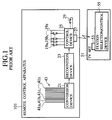
- FIG.1 is a block diagram showing structures of a remote control transmission apparatus (hereinafter referred to as remote control apparatus) of television set (hereinafter referred to as TV set) using the conventional finger verification system and the TV set.
- remote control apparatus a remote control transmission apparatus
- TV set television set
- a particular person is recognized according to information related to a shape of the finger which is in contact with the rear face of the remote control apparatus and a permission for access to a pay channel is dispatched thereby preventing infants from playing with channel change.
- the rear face of the remote control apparatus has an electrode face 43 in which a plurality of linear electrodes 41a, 41b, 41c, ⁇ 41z are disposed in parallel to each other.
- the respective electrodes 41a-41z composing the electrode face 43 are connected to a conversion device 21. With a minute voltage applied between the respective electrodes 41a-41z, electric resistance between the adjacent electrodes is measured and this resistance value is coded by the conversion device 21.
- the coded information is transmitted to a recognition device 23 and verified with information of a particular person P already registered. If the recognition device 23 recognizes that the finger making contact with the rear face of the remote control apparatus 101 is a finger of a subscriber or a particular person P, the recognition device 23 outputs a permission information to a control device 25.
- a control signal for instructing to select the pay channel is transmitted from a infrared ray emitting portion 27 of the control device 25 to a infrared ray receiving portion 53 of a station selection/control device 55 of a TV set 51. Consequently, the pay channel is selected by the station selection/control device 55. Because even if other person than the particular person touches the remote control apparatus 101, the recognition device 23 does not dispatch permission information, he cannot watch or listen to the pay channel.
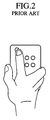
- the electrode face is provided on only the rear face of the remote control apparatus, there is a case that a proper operator is not recognized to be a subscriber particular person, depending on a way of gripping the remote control apparatus. For example, if the remote control apparatus is gripped in a style shown in FIG.2 and a button is pressed by a forefinger, the side face of the remote control apparatus is gripped with the thumb and middle finger, so that the electrode face on the rear face thereof is not contacted by the finger. Therefore, the person is not recognized.
- the pay channel contains information inappropriate for children. For example, if a subscriber presses the pay channel button by mistake when he is watching TV together with his children, they happen to know a presence of the pay channel.
- a finger verification system comprising: a case having a plurality of grooves disposed on a rear face thereof; a plurality of electrode faces which are provided in each of the plurality of the grooves and formed with a plurality of electrodes arranged in the same direction as an extension direction of the plurality of the grooves; and a recognition means for, when a finger makes a contact with any of the plurality of the electrode faces, recognizing a particular person related to the finger according to an impedance distribution pattern group obtained by measurement based on the plurality of the electrodes.
- the number of the plurality of the grooves is two and an angle formed by the plurality of the grooves is 5°-30°.
- the case is provided with the plurality of the grooves on a rear face thereof and contains a rotary body rotatable around a shaft vertical to the rear face.
- the above finger verification system further comprises a spring-back mechanism which positions the rotary body at a predetermined position under no load condition and when a load is applied in any direction of normal and reverse directions, rotates the rotary body in the direction of the load from the predetermined position and when the load is removed, returns the rotary body to the predetermined position.
- a finger verification system comprising: a case containing grooves disposed on each of two side faces; two electrode faces which are provided in each of the grooves and formed with a plurality of the electrodes arranged in the same direction as an extension direction of the grooves; and a recognition means for, when a finger makes a contact with any of the two electrode faces, recognizing a particular person related to the finger according to an impedance distribution pattern group obtained by measurement using the plurality of the electrodes.
- a finger verification system comprising: electrode faces in which a plurality of electrodes are arranged in parallel to each other; a conversion means which, when a finger is placed on the plurality of the electrodes, measures impedance values between each of the plurality of the electrodes and the finger and converts the impedance values to information indicating a series of the impedance values; a recognizing means for recognizing whether or not a person related to the finger is a particular person preliminarily registered according to information indicating the series of the impedance value; a notifying means for notifying that the particular person has been recognized by the recognizing means; a response confirmation means for determining whether or not a predetermined response is inputted within a first predetermined time interval since a notification from the notifying means; and a control means for, when it is determined that the predetermined response is inputted within the first predetermined time interval by the response confirmation means, controlling so as to enable a predetermined operation within a second predetermined time interval.
- a finger verification system comprising: electrode faces in which a plurality of electrodes are arranged in parallel to each other; a conversion means which, when a finger is placed on the plurality of the electrodes, measures impedance values between each of the plurality of the electrodes and the finger and converts the impedance values to information indicating a series of the impedance values; a recognizing means for recognizing whether or not a person related to the finger is a particular person preliminarily registered according to information indicating the series of the impedance value; a notifying means for notifying that the particular person has been recognized by the recognizing means; and a control means which, when a predetermined operation is not carried out within a third predetermined time interval since a notification by the notifying means, performs a predetermined control.
- the notifying means notifies that the particular person has been recognized by dispatching light or sound.
- a finger verification system comprising: a storage means for storing information of operating function specified for each person; electrode faces in which a plurality of electrodes are arranged in parallel to each other; a conversion means which, when a finger is placed on the plurality of the electrodes, measures impedance values between each of the plurality of the electrodes and the finger and converts the impedance values to information indicating a series of the impedance values; a recognizing means for recognizing whether or not a person related to the finger is a particular person preliminarily registered according to information indicating the series of the impedance value; and a control device which, when the particular person is recognized by the recognizing means, controls so that the operating function specified for the particular person is achieved with reference to the information about the operating function stored in the storage means.
- a finger verification system comprising: a case which contains a rotary body which has a plurality of holes and is rotatable around a shaft vertical to a rear face thereof, the case having a plurality of electrode faces formed with a plurality of electrodes which form a part of concentric circles on a rear face thereof under the rotary body; and a recognition means which, when a finger makes contact with any of the plurality of the electrode faces, recognizes a particular person related to the finger according to an impedance distribution pattern group obtained by measurement using the plurality of the electrodes.
- the above finger verification system further comprises a spring-back mechanism which positions the rotary body at a predetermined position under no load condition and when a load is applied in any direction of normal and reverse directions, rotates the rotary body in the direction of the load from the predetermined position and when the load is removed, returns the rotary body to the predetermined position.
- a finger verification system comprising: a case which has a plurality of grooves on rear and side faces thereof and a movable portion movable in a length direction; a plurality of electrode faces which are provided in each of the plurality of the grooves and formed with a plurality of the electrodes arranged in the same direction as an extension direction of the plurality of the grooves; and a recognition means which, when a finger makes contact with any of the plurality of the electrode faces, recognizes a particular person related to the finger according to an impedance distribution pattern group obtained by measurement using the plurality of the electrodes.
- the above finger verification system further comprises a sliding mechanism for positioning the movable portion gradually in the length direction.
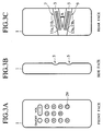
- FIGs.3A-3C show an appearance of a remote control apparatus employing a finger verification system according to a first embodiment of the present invention.
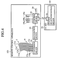
- FIG.4 is a block diagram showing an electric circuit of the remote control apparatus and a television set. The same reference numerals as in FIG.1 are attached to the same components having the same function as a conventional remote control apparatus. In this embodiment, the forefinger is used for finger verification.
- FIGs.3A-3C show the front, side and rear faces of the remote control apparatus 1 for remote-controlling the television set (hereinafter referred to as TV set) (not shown).
- the front face of the remote control apparatus 1 contains ON/OFF button for turning on/off the power of the TV set, VOL +/- button for adjusting sound volume, ten-key (1-0) button for selecting a channel, and a pay channel button 29.
- two grooves 3, 5 are formed obliquely at different angles on the rear face of the remote control apparatus 1 while the grooves 3, 5 have electrode faces 7, 9 respectively.
- the electrode faces 7, 9 have a plurality of linear electrodes 11a, 11b, 11c, ⁇ 11z and a plurality of linear electrodes 13a, 13b, 13c, ⁇ 13z in a substantially perpendicular direction to the extension of each groove.
- FIG.4 is a block diagram showing the remote control apparatus and TV set.
- the remote control apparatus 1 comprises a plurality of the electrodes 11a, 11b, 11c, ⁇ 11z constituting the electrode face 7, a plurality of the electrodes 13a, 13b, 13c, ⁇ 13z constituting the electrode face 9, a conversion device 21, a recognition device 23 and a control device 25.
- buttons 19a-19z including the ON/OFF button, VOL +/- button, and the ten-key button and the like, the pay channel button 29 and an infrared ray emitting portion 27.
- the TV set 51 controlled by the remote control apparatus 1 contains an infrared ray receiving portion 53 and a station selection/control device 55.
- the pluralities of the electrodes provided on the electrode faces 7, 9 on the rear face of the remote control apparatus 1 are connected such that the corresponding electrodes 11a and 13a, 11b and 13b, 11c and 13c, ⁇ 11z and 13z are connected to each other and they are connected to the conversion device 21.
- a fine voltage is applied between the electrodes 11a (13a) and 11z(13z) so as to measure an electric resistance between adjacent electrodes and this resistance value is coded by the conversion device 21.
- the coded information is transmitted to the recognition device 23 and verified with particular personal information registered in a memory unit (not shown) provided in the recognition device 23. If the recognition device 23 recognizes a finger contacting the rear face of the remote control apparatus 1 to be a finger of a particular person P who is a subscriber, the recognition device 23 transmits a permission information to the control device 25.
- a control signal for selecting the pay channel is transmitted from the infrared ray emitting portion 27 of the control device 25 to the infrared ray receiving portion 53 of the TV set 51 and then the station selection/control device 55 selects a pay channel.
- the recognition device 23 does not transmit the permission information, and therefore the pay channel cannot be watched or listened to.
- the transmission medium is not restricted to infrared ray but it is permissible to use visible ray, ultraviolet ray, supersonic wave, electronic wave or the like.
- FIGs.5A-5D show four types of ways for griping the remote control apparatus which can be considered when it is operated by a single hand or both hands.
- the remote control apparatus 1 When the remote control apparatus 1 is operated with the forefinger placed thereunder as shown in the same figure, the forefinger of the right hand is embedded in the groove 3 and the forefinger of the left hand is embedded in the groove 5.
- the reason why the angles of the grooves 3, 5 are different from each other is that the hand structure of a person is taken into account as described above.
- a groove considering a structure of a man's hand is provided on the rear face of the remote control apparatus and the electrode face is provided on the surface of this groove.
- FIGs.6A, 6B and 7A, 7B show application examples.
- FIGs.6A, 6B show cases in which the body of the remote control apparatus is supported by other fingers than the forefinger and the forefinger is used for controlling the button as shown in FIG.2. Because the middle finger is in contact with the side face of the remote control apparatus, the grooves 3, 5 and the electrodes 11a-11z, 13a-13z are provided on this portion. The right and left side faces have grooves to allow recognition of both the right and left hands.
- the other structure is just the same as the first embodiment.
- FIGs.7A, 7B show a case of preventing the remote control apparatus from being operated while placed on a table. By forming the shape of the rear face thereof in a convex formation, the remote control apparatus is difficult to operate.
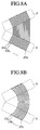
- each groove is formed with the electrodes 11a-11z and electrodes 13a-13z according to the present embodiment, it is permissible to form a single electrode face using curved electrodes 15a-15z as shown in FIGs.8A, 8B.
- the electrodes of each groove are formed so that the center portions thereof are composed of short electrodes not so as to prevent short-circuit in the center portion.
- an angle A between the grooves 3 and 5 is about 5-30° in FIG.3C, the user can grip the remote control apparatus without any feeling of incongruity. Further, it is needless to say that four electrodes can be allocated on the rear and side faces of the remote control apparatus.
- a plurality of the electrode faces are provided at positions easy for the finger on the side face or rear face of the remote control apparatus to make contact, so that personal recognition is automatically carried out without any particular user's consciousness thereby providing no stress to the user.
- the user does not feel clearly that he has been recognized, a problem occurs.
- the pay channel includes programs unfavorable for low ages.
- the pay channel is selected by mistake, the children come to watch a unfavorable program for low age group. In this case, even if the channel is switched in a hurry, an influence upon the children is not small.
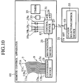
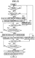
- FIG.10 shows a block diagram showing a structure of a circuit according to a second embodiment of the present invention and FIG.11 shows a flow chart for explaining the operation thereof.
- the same reference numerals are attached to the components having the same function as the first embodiment and a description thereof is omitted.
- the remote control apparatus 61 comprises a plurality of electrodes 11a, 11b, 11c, ⁇ 11z, a plurality of electrodes 13a, 13b, 13c, ⁇ 13z, a conversion device 21, a recognition device 23 and a control device 63.
- the control device 63 contains a light emitting device 33 for emitting red/green lights, timer 35, confirmation button 31, and pay channel button 29.
- the resistance value between the adjacent electrodes 11a(13a) and 11z(13z) changes from open (substantially infinite) to several k ⁇ - several tens k ⁇ due to skin contact.
- the conversion device 21 determines that finger contact occurs (step S11) and successively measures a resistance between the adjacent electrodes. These resistance values are converted from analog to digital and the result is transmitted to the recognition device 23.
- the recognition device 23 verifies a pattern registered in the recognition device 23 with a resistance pattern transmitted from the conversion device 21 so as to determine whether he is a particular person P (step S13). If he is the particular person P, the permission information notifying it is sent to the control apparatus 63.
- control apparatus 63 If a notification that he is the particular person P as a result of the determination is received, the control apparatus 63 turns on the light emitting device 33, for example, in green (step S15) so as to notify the user that the pay channel is available. Next, the control device 63 initializes the timer 35 and starts the operation thereof (step S17).
- control device 63 After the operation of the timer 35 is started, the control device 63 loops the steps of time-out determination (step S19) and determining whether or not the confirmation button is pressed (step S23) so as to wait for any of such events.
- step S19 Unless the confirmation button 31 is pressed within a first predetermined time interval after the light emitting device 33 turns green, time-out is determined at step S19, the light emitting device 33 is turned off (step S21) and even if the pay channel button 29 is pressed after that, it becomes invalid.
- step S23 a determination of step S23 is YES.
- the control device 63 changes the lighting from green to red or turns off green and turns on red (step S25), notifying that a user's response has been received, and then the processing is moved to step S27.
- the timer 35 is initialized so as to validate the pay channel button only within a second time interval so as to start the timer operation.
- control device 63 After the operation of the timer 35 is started, the control device 63 loops the steps of time-out determination (step S29) and determining whether or not the pay channel button has been pressed (step S29) so as to wait for any of such events.
- control device 33 transmits a control signal to the station selection/control device 55 so as to select a pay channel (step S35) and turns off the light emitting device 33 (step S37).
- step S29 Unless the pay channel button is pressed within the second predetermined time interval, a determination of step S29 is time-out. Then, the light emitting device 33 is turned off (step S31) and even if the pay channel button 29 is pressed after that, it is invalid.
- the finger verification system having such a structure, it is possible to prevent the pay channel from being selected by mistake. Further, even if user leaves there after the recognition device 23 transmits the permission signal, because the pay channel cannot be watched or listened to after a predetermined time interval, the pay channel is not watched or listened to by a third party. This is the same even after the confirmation button 31 is pressed.
- the object of the light emitting device 33 is to notify that a particular person P has been recognized, it is needless to say that this means can be replaced by a sound producing means or both the means can be provided.
- the light emitting device 33 of this embodiment is so structured to turn green when the recognition of a person is performed and turn red when the confirmation button is pressed
- other ways are permitted because the object of this light is to notify a particular user. For example, it is permissible to so construct that it turns a certain color if the recognition is performed and it blinks in that color when the confirmation is carried out. Further, it is permissible to notify user by using on-screen display function of displaying a message on the screen of the TV set 51.
- FIG.12 shows a third embodiment of the present invention. To simplify a description thereof, this embodiment will be described based on the first embodiment, however it is possible to realize it if the second embodiment is combined.
- the same reference numerals are attached to the components having the same function as the first embodiment, and a description of a duplicate content is omitted.
- a remote control apparatus 71 comprises a plurality of electrodes 11a, 11b, 11c, ⁇ 11z, a plurality of electrodes 13a, 13b, 13c, ⁇ 13z, a conversion device 21, a recognition device 23, and a control device 73.
- the control device 71 contains a timer 35 and a pay channel button 29.
- the control device 73 starts the timer 35.
- the control signal for instructing the station selection/control device 55 to select the pay channel is outputted.
- the timer 35 is reset and starts counting again if the power supply is turned off, the channel is changed or any other operation is carried out.
- the timer 35 outputs a time information saying that a predetermined time has passed to the control device if the predetermined time, for example, an hour has passed.
- the control device 73 outputs an alarm information to the station selection/control device 55 according to that time information.
- the station selection/control device 55 multiplexes messages saying, for example, "the power supply will be turned off some minutes after" or "make recognition with remote control apparatus again".
- the control device 73 resets the timer 35 and instructs the station selection/ control device 55 to erase the aforementioned messages. Unless the permission signal is inputted within a predetermined time, the station selection/control device 55 is controlled to be turned off.
- the finger verification system having such a structure, even if a particular registered individual leaves the pay channel ON carelessly, the power is automatically turned off, so that unlimited increase of charge due to forgetting to turn off the power can be prevented. Further, it is prevent the pay TV from being watched by a unrelevant person because a registered person forgets to turn off.
- the present invention is formed so that user is notified by sending a message to the TV screen, it is needless to say that this can be realized by other means.
- the other portion than the screen can be made to indicate or audio message produced by a buzzer or voice synthesizer may be used.
- a fourth embodiment has an object of providing various services by recognizing plural persons.
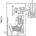
- FIG.13 shows a structure of the fourth embodiment.
- the remote control apparatus 81 comprises a plurality of electrodes 11a, 11b, 11c, ⁇ 11z. a plurality of electrodes 13a, 13b, 13c, ⁇ 13z, a conversion device 21, a recognition device 23 and a control device 83.
- the recognition device 23 contains a storage unit 231 for storing data for recognizing a plurality of persons, and specifies a person gripping the remote control apparatus to send information to the control device 83.
- the control device 83 transmits control signal to the station selection/control device 55 according to this information, which controls a selection channel, sound volume, sound quality, picture quality and the like corresponding to each person.
- a person having a weak acoustic sense grips the remote control apparatus, it is controlled so as to raise the sound level slightly.
- the remote control apparatus it is controlled so as to raise the sound level slightly.
- aged persons have a lowered sensitivity to high range components in visual sense. Therefore, when the aged person uses it, it is convenient if the picture quality is controlled so that enhancer level is raised.
- channel selection a channel which is automatically selected when the power is turned on can be set to a channel which everybody usually watches or listens to.
- TV watch time or time range can be restricted for children.
- TV game or the like compels a person to look fixedly at the screen, it is possible to consider restricting of daily use time or use time range or game play time or the like for children.
- parent's finger is recognized so as to enable setting of various limitations. Further, it is possible to limit use time per month for only the pay broadcasting. Some pay TV services provide no-charge program for a short time. In this case, it is possible to limit the number of use for each person.
- an advantage of applying capacitive coupling is that when the finger is not in firm contact with an output electrode, capacitive coupling strength substantially reversely proportional to a distance between the finger and the output electrode is obtained so that an output voltage of a detecting circuit proportional to this coupling strength can be obtained. That is, in measurement of resistance, even when only a substantially infinite resistance can be obtained because there is no contact between the finger and electrode, the capacitive coupling is capable of obtaining a detecting circuit output reflecting an uneven shape of the finger. Thus, the amount of information increases so as to raise recognition accuracy.
- FIG.14 shows a conversion portion 300 for converting the finger shape to impedance pattern, which corresponds to the electrodes 11a, 11b, ⁇ 11z, 13a, 13b, ⁇ 13z and the conversion device 21 of FIG.4.
- the conversion portion 300 comprises a plurality of output linear electrodes 200a, 200b, ⁇ 200z, 201a, 201b, ⁇ 201z, input electrodes 202a, 202b, a plurality of analog switches 203 which are selectively closed so as to apply a high frequency voltage upon the output linear electrodes, an oscillator 204 for supplying a fine high frequency current to the output linear electrodes through the analog switches 203, a timing pulse generator 205 for generating timing pulses for opening/closing the analog switches 203, a terminating resistor 208 connected between the input electrodes 202a, 202b and reference potential (grounding), a detecting circuit 206 for detecting a high frequency voltage of the terminating resistor 208 and an A/D converter 207 for A/D converting DC voltage outputted from the detecting circuit 206.
- the finger is placed on a pair of the output linear electrodes 200a - 200z and the input electrode 202a or a pair of the output linear electrodes 201a - 200z and the input electrode 202b.
- the analog switch 203 is switched to a direction of the finger length so that an output of the oscillator 204 is successively connected to the output linear electrodes 200a-200z or the output linear electrodes 201a-201z.
- the high frequency output applied to the output linear electrodes 200a-200z or the output linear electrodes 201a-201z generates a high frequency voltage on both ends of the terminating resistor 208 one of which is connected to the input electrode 202a or 202b by the capacitive coupling between the finger shape and electrode.
- a generated high frequency voltage is detected by the detecting circuit 206 and converted to digital signal by the A/D converter 207.
- the timing pulse generator 205 generates a signal for controlling changeover of the analog switch 203 and sampling timing of the A/D converter 207.
- the capacitive coupling between the finger and the output electrode is strengthened and the output voltage of the detecting circuit 206 increases. Conversely, at a portion where the finger is not in firm contact with the output electrode, the capacitive coupling between the finger and the output electrode weakens and the output voltage of the detecting circuit 206 drops. Accordingly, an output voltage corresponding to a distance between the finger and the electrode can be obtained.
- the finger unevenness pattern can be detected according to digital signals obtained by the A/D converter 207, so that verification with the finger is enabled.
- the digital signal is transmitted to the recognition device 23 in FIGs. 4, 10, 12, and 13.
- the following processing is carried out in a common way in the first-fourth embodiments.
- the impedance of the input electrode 202 is required to be sufficiently low, an area of the input electrodes contacting the finger needs to be sufficiently larger than that of the output electrodes. Further, because the input electrodes need to be always in contact with the finger, they are desired to be located near the finger roots. Thus, in this case, the electrode shape is slightly different from a case in which electric resistance is used.
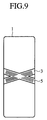
- FIG.15A In a case when such electrodes are allocated on the rear side of the remote control apparatus 1 shown in FIG.3C, an arrangement shown in FIG.15A is provided. Likewise, in a case when such electrodes are allocated on the side of the remote control apparatus 1 shown in FIGs.6A, 6B, an arrangement shown in FIG.15B is provided. Further, in a case when a single electrode plane is formed as shown in FIGs. 8A, 8B, the same effect can be obtained by forming curved electrodes in the manner shown in FIGs. 16A, 16B. Further, in a case when the electrode groups intersect each other at the center as shown in FIG.9, the electrodes can achieve the same purpose.
- the verification is automatically performed regardless of user's consciousness so that the user does not feel stress.
- the groove fixedly provided may not correspond sufficiently to each need.
- FIGs.17A-17C, 18A-18C The fifth embodiment of the present invention is shown in FIGs.17A-17C, 18A-18C.
- the basic structure is the same as the first embodiment and the same reference numerals are attached to the components having the same function, and a description thereof in detail is omitted.
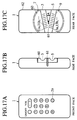
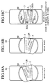
- FIGs.17A, 17B, 17C show the front face, the side face and the rear face thereof respectively and FIGs.18A-18C show the rear faces.
- the remote control apparatus 1 of the present embodiment comprises a main body 62 and a rotary body 60.
- the rotary body 60 contains the electrode faces 7, 9 and the grooves 3, 5.
- a rotary shaft 61 supports the rotary body 60 rotatably relative to the main body 62, as shown in FIGs.18A, 18B, the rotary body 60 can be rotated counterclockwise or clockwise only by a movable angle B relative to the rotary shaft 61.
- the movable angle B is provided so as to absorb a personal difference in the shape, size and the like of the hand, therefore if about 5° is preserved, it is sufficient.
- the conversion device 21 of FIG.4 is contained in the rotary body 60 and generated signals are transmitted to the recognition device 23 of FIG.4. If the present embodiment is applied to the case in which the verification is carried out by using electrostatic capacity as shown in FIG.14, the allocation of the electrodes is slightly different as shown in FIG.18C. That is, at one end of the output electrodes 200a-200z and 201a-201z respectively, the input electrodes 202a, 202b are allocated.
- the rotary body 60 is rotated for fine adjustment, when the remote control apparatus is griped with an opposite hand, the angle in which the finger contacts may be deviated so that the user may feel a sense of incongruity. Then, when the remote control apparatus is released from the hand, it is desired that the rotary body 60 is returned to the center position.
- a spring-back mechanism is provided, which returns the rotary body 60 to the center position when no load is applied to the rotary body 60.
- the same mechanism is used for dial mechanism for controlling rapid feed, feed back or the like in home VTR.
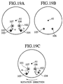
- FIGs.19A-19C shows an example of the spring-back mechanism.
- FIG.19A shows the main body 62 and FIG.19B shows the rotary body 60.
- the rotary shaft 61 is a center of the rotation.
- Each end of elastic bodies 101, 102 is fixed to fixing points 107, 108 so as to apply a force of returning clockwise/counterclockwise. Stoppers 103, 104 support the elastic bodies 101, 102 trying to return.
- the rotary body 60 has protrusions 105, 106.
- the protrusions 105, 106 are allocated so that they are located at positions a, b of FIG.19A when the rotary body 60 matches the main body.
- the rotary body is as shown in FIG.19A when a load in rotation direction is not applied.
- a state shown in FIG.19C is produced.
- the protrusion 105 moves to the position a r while the protrusion 106 moves to the position br .
- the elastic body 107 is not changed relative to the state shown in FIG.19A, a further load is applied to the elastic body 108 in the clockwise direction so that it tries to return in the counterclockwise direction. If the finger is released so as to release the load, the state of FIG.19A is regained. If an opposite load is applied thereto, a force of returning to the state of FIG.19A is generated by the elastic body 107 likewise.
- FIGs.20A-20D, 21A-21C and 22A-22E Examples in which the fifth embodiment is achieved with a simple structure are shown in FIGs.20A-20D, 21A-21C and 22A-22E.
- a simple structure can be achieved.
- FIG.20A shows a front face
- FIG.20B shows a side face
- FIG.20C shows a rear face
- FIG.21A shows a side face of the main body 75
- FIG.21B shows a rear face thereof.
- FIGs.22A-22D show detailed views of the rotary body 70 and FIG.22E shows a perspective view thereof.
- the electrode 73 is allocated on a circular base plate 74 formed in the main body 75 of the remote control apparatus 1.
- the electrodes are allocated as shown by 15a, 15b, ⁇ 15z of FIG.8B.
- the groove 71 of the rotary body 70 has V-shaped hole 76.
- the rotary body 70 covers the base plate 74 such that it is movable in only the rotation direction.
- the finger surface contacts the electrodes 15a, 15b, ⁇ 15z through the V-shaped hole 76 so as to enable the aforementioned verification.
- the rotary body 70 covers the base plate 74 so as to secure a movement in the rotation direction.
- the rotary shaft 61 is not necessary.
- the allocation of the electrodes is slightly different, such that the input electrodes 202a, 202b are disposed at each end of the plural electrodes 200a-200z, 201a-201z.
- the appearances of the rear face are shown in FIGs.20D, 21C.
- the circuit diagram shown in FIG.14 can be applied to connection between the electrode groups and conversion device.
- FIGs.23-26 show examples in which the detecting face is allocated on the rear face of the remote control apparatus 1.
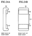
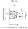
- FIGs.23A-23C and 24A-24B show the main body 84 of the remote control apparatus 1 and FIGs.25A, 25B and 26 show a detail of the movable portion 81.
- FIGs.23A, 23B, 23C, 24A, and 24B show the front face, side face, and rear face and side face and rear face of the main body 84.
- FIG.25A shows a detail of the movable portion 81 and FIG.25B shows a perspective view thereof.
- the present embodiment comprises the main body 84 and movable portion 81.
- the center portion of the main body 84 is dented such that it is formed in a substantially concave shape.
- the movable portion 81 is formed in a substantially convex shape if the side portion is excluded. Therefore, the movable portion 81 is capable of moving on slide faces 82, 83 of the main body 84 shown in FIGs.24A, 24B.
- the length L1 of FIG.24B and the length L2 of FIG.25A, 26 have a relation of L1 > L2.
- the movable portion 81 is movable in the length of (L1 - L2). That is, the user can move the movable portion 81 within the length of (L1 - L2) freely so as to adjust.
- the conversion device 21 and recognition device 23 of FIG.4 are incorporated in the movable portion 81.
- the permission information obtained from the recognition device 23 is transmitted to the control device 25.
- a following processing is carried out in the same manner as the first-fourth embodiments.
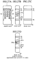
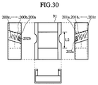
- FIGs.27A-30 show examples in which the detecting face allocated on the side face of the remote control apparatus 1 is moved vertically.
- FIGs.27A, 27B, 27C show the front face, side face and rear face thereof respectively
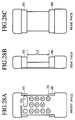
- FIGs.28A, 28B, 28C show the front face, side face and rear face of the main body 94.
- FIG.29A is a detailed diagram of the movable portion 91
- FIG.29B is a perspective view of the movable portion 91.
- the remote control apparatus 1 comprises a main body 94 and a movable portion 91.
- Grooves 92, 93 of the movable portion 91 correspond to the grooves 3, 5 of FIG.6A of the first embodiment.
- the center portion of the main body 94 is dented as viewed from the side, such that the dented portion is substantially concave.
- the movable portion 91 is substantially convex if the side portion thereof is excluded. Therefore, the movable portion 91 moves on slide faces 95, 96 of the main body 94 of FIGs.27A-27C.
- the length L1 of FIG.28B and the length L2 of FIGs.29A, 29B and 30 have a relation of L1 > L2.
- the length of (L1 - L2) is a length in which the movable portion 91 can move. That is, user can move the movable portion 91 freely within the length of (L1 - L2) so as to adjust.
- the conversion device 21 and recognition device 23 of FIG. 4 are incorporated in the movable portion 91, so that they are operated in the same manner.
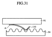
- FIG.31 shows an example in which a vertical position can be gradually set.
- An elastic body 110 is fixed to part of the movable portion 91 at a fixing position.
- Part of the main body 94 shows a wave shape as shown in FIG.31 and part of the elastic body 110 contacts the main body 94.
- the movable portion 91 is stabilized by concave portion of this wave shape portion by a repelling force of the elastic body 110. That is, the user can select an optimum position from any concave portions depending on the size, shape, and the like of the hand.
- FIG.23D shows an appearance of a case in which the electrodes disposed on the rear face of the remote control apparatus 1 are movable vertically
- FIG.26 is a detailed drawing of the movable portion 81.
- FIG.27D shows a side face
- FIG.30 shows a detail of the movable portion 91.
- input electrodes 202a, 202b are disposed at each end of the plural output electrodes 200a-200z, 201a-201z. Then, the circuit diagram shown in FIG.14 can be applied to connection between the electrodes and conversion device.
Landscapes
- Engineering & Computer Science (AREA)
- Human Computer Interaction (AREA)
- Physics & Mathematics (AREA)
- General Physics & Mathematics (AREA)
- Theoretical Computer Science (AREA)
- Multimedia (AREA)
- Biophysics (AREA)
- Cardiology (AREA)
- General Health & Medical Sciences (AREA)
- Heart & Thoracic Surgery (AREA)
- Physiology (AREA)
- Life Sciences & Earth Sciences (AREA)
- Health & Medical Sciences (AREA)
- Details Of Television Systems (AREA)
- Collating Specific Patterns (AREA)
Applications Claiming Priority (3)
| Application Number | Priority Date | Filing Date | Title |
|---|---|---|---|
| JP10526/97 | 1997-01-23 | ||
| JP1052697 | 1997-01-23 | ||
| JP1052697 | 1997-01-23 |
Publications (2)
| Publication Number | Publication Date |
|---|---|
| EP0855666A2 true EP0855666A2 (de) | 1998-07-29 |
| EP0855666A3 EP0855666A3 (de) | 1999-09-15 |
Family
ID=11752705
Family Applications (1)
| Application Number | Title | Priority Date | Filing Date |
|---|---|---|---|
| EP98101194A Withdrawn EP0855666A3 (de) | 1997-01-23 | 1998-01-23 | Fingerprüfungssystem |
Country Status (3)
| Country | Link |
|---|---|
| US (1) | US6144756A (de) |
| EP (1) | EP0855666A3 (de) |
| KR (1) | KR19980070742A (de) |
Cited By (3)
| Publication number | Priority date | Publication date | Assignee | Title |
|---|---|---|---|---|
| WO2001020538A3 (en) * | 1999-09-15 | 2002-09-26 | Quid Technologies Llc | Biometric recognition utilizing unique energy characteristics of an individual organism |
| EP1587341A4 (de) * | 2003-12-19 | 2010-02-24 | Panasonic Corp | Verfahren und einrichtung zum einstellen des audioausgangspegels |
| US8437510B2 (en) | 2000-04-18 | 2013-05-07 | Semiconductor Energy Laboratory Co., Ltd. | System and method for identifying an individual |
Families Citing this family (10)
| Publication number | Priority date | Publication date | Assignee | Title |
|---|---|---|---|---|
| JP2000172833A (ja) * | 1998-12-10 | 2000-06-23 | Omron Corp | 指紋照合装置 |
| JP3663075B2 (ja) * | 1999-04-05 | 2005-06-22 | シャープ株式会社 | 情報処理装置 |
| US20030108227A1 (en) * | 2001-12-11 | 2003-06-12 | Koninklijke Philips Electronics N.V. | Remote control with the fingerprint recognition capability |
| US6970098B1 (en) | 2004-08-16 | 2005-11-29 | Microsoft Corporation | Smart biometric remote control with telephony integration method |
| US8408456B2 (en) * | 2006-12-04 | 2013-04-02 | Verizon Services Organization Inc. | Systems and methods for controlling access to media content by detecting one or more user fingerprints |
| US8362875B2 (en) * | 2008-09-24 | 2013-01-29 | Panasonic Corporation | Secure system for non-covert user authentication and identification |
| JP6578797B2 (ja) * | 2015-08-06 | 2019-09-25 | オムロン株式会社 | 操作装置およびx線撮影ユニット |
| US10318718B2 (en) * | 2016-09-23 | 2019-06-11 | Ncr Corporation | Voice authentication within messaging systems |
| US10331867B2 (en) * | 2016-10-05 | 2019-06-25 | Plantronics, Inc. | Enhanced biometric user authentication |
| US10126080B2 (en) * | 2017-03-09 | 2018-11-13 | Roy Martin | Biometric firearms safety system |
Family Cites Families (9)
| Publication number | Priority date | Publication date | Assignee | Title |
|---|---|---|---|---|
| US3781855A (en) * | 1970-03-13 | 1973-12-25 | Identification Systems Inc | Fingerprint identification system and method |
| US4467545A (en) * | 1982-08-12 | 1984-08-28 | Shaw Jr Frederic A | Personalized safety method and apparatus for a hand held weapon |
| US4857916A (en) * | 1987-02-26 | 1989-08-15 | Bellin Robert W | System and method for identifying an individual utilizing grasping pressures |
| US4792226A (en) * | 1987-02-27 | 1988-12-20 | C.F.A. Technologies, Inc. | Optical fingerprinting system |
| US5073949A (en) * | 1989-03-16 | 1991-12-17 | Kabushiki Kaisha Toshiba | Personal verification apparatus |
| US5559504A (en) * | 1993-01-08 | 1996-09-24 | Kabushiki Kaisha Toshiba | Surface shape sensor, identification device using this sensor, and protected system using this device |
| JPH07168930A (ja) * | 1993-01-08 | 1995-07-04 | Toshiba Corp | 表面形状センサ、並びにそれを用いた個体認証装置および被起動型システム |
| US5546471A (en) * | 1994-10-28 | 1996-08-13 | The National Registry, Inc. | Ergonomic fingerprint reader apparatus |
| TW303441B (de) * | 1995-03-29 | 1997-04-21 | Trw Inc |
-
1998
- 1998-01-21 US US09/010,026 patent/US6144756A/en not_active Expired - Fee Related
- 1998-01-23 KR KR1019980001995A patent/KR19980070742A/ko not_active Abandoned
- 1998-01-23 EP EP98101194A patent/EP0855666A3/de not_active Withdrawn
Cited By (5)
| Publication number | Priority date | Publication date | Assignee | Title |
|---|---|---|---|---|
| WO2001020538A3 (en) * | 1999-09-15 | 2002-09-26 | Quid Technologies Llc | Biometric recognition utilizing unique energy characteristics of an individual organism |
| US8437510B2 (en) | 2000-04-18 | 2013-05-07 | Semiconductor Energy Laboratory Co., Ltd. | System and method for identifying an individual |
| US8805032B2 (en) | 2000-04-18 | 2014-08-12 | Semiconductor Energy Laboratory Co., Ltd. | System and method for identifying an individual |
| US9008377B2 (en) | 2000-04-18 | 2015-04-14 | Semiconductor Energy Laboratory Co., Ltd. | System and method for identifying an individual |
| EP1587341A4 (de) * | 2003-12-19 | 2010-02-24 | Panasonic Corp | Verfahren und einrichtung zum einstellen des audioausgangspegels |
Also Published As
| Publication number | Publication date |
|---|---|
| US6144756A (en) | 2000-11-07 |
| KR19980070742A (ko) | 1998-10-26 |
| EP0855666A3 (de) | 1999-09-15 |
Similar Documents
| Publication | Publication Date | Title |
|---|---|---|
| US6144756A (en) | Finger verification system | |
| US5920642A (en) | Ergonomic fingerprint reader apparatus | |
| US5767841A (en) | Two-sided trackball | |
| EP1285531B1 (de) | System zum betreiben eines unterhaltungselektronikgerätes | |
| EP0721169B1 (de) | Drahtlose Führungsvorrichtung für eine Cursorfernsteuerung | |
| US20030108227A1 (en) | Remote control with the fingerprint recognition capability | |
| AU771017B2 (en) | Method and apparatus for setting programmable features of an appliance | |
| US8825113B2 (en) | Portable terminal and driving method of the same | |
| JPH0686185A (ja) | テレビジョン受像機の制御装置及びその制御方法 | |
| US20050037814A1 (en) | Mobile information communication terminal program and recording medium containing the program | |
| US20080169902A1 (en) | Television receiver | |
| WO2004105364A1 (en) | Keypad for portable electronic devices | |
| US20020019732A1 (en) | Interactivity using voice commands | |
| US20040090423A1 (en) | Remote controlled video display GUI using 2-directional pointing | |
| JPH10262951A (ja) | 指照合システム | |
| JP2001504638A (ja) | 接続装置 | |
| EP2249285B1 (de) | Verfahren und Programm zum Steuern des Abonnentengeräts und Abonnentengerät | |
| JP2000244830A (ja) | 視聴制限機能付きテレビジョン装置及び画像再生装置並びにそれらのリモコン装置 | |
| US8333658B2 (en) | Determining authorization to manipulate a token | |
| US20070146193A1 (en) | Remote control device and information reproducing system | |
| JP2000011791A (ja) | リモコン装置 | |
| CN1182336A (zh) | 单独的选呼接收机 | |
| JP2001057693A (ja) | 遠隔操作装置 | |
| JPH0918774A (ja) | 視線による機能設定装置 | |
| JPH10228686A (ja) | 磁気記録再生装置 |
Legal Events
| Date | Code | Title | Description |
|---|---|---|---|
| PUAI | Public reference made under article 153(3) epc to a published international application that has entered the european phase |
Free format text: ORIGINAL CODE: 0009012 |
|
| 17P | Request for examination filed |
Effective date: 19980220 |
|
| AK | Designated contracting states |
Kind code of ref document: A2 Designated state(s): AT BE CH DE DK ES FI FR GB GR IE IT LI LU MC NL PT SE |
|
| AX | Request for extension of the european patent |
Free format text: AL;LT;LV;MK;RO;SI |
|
| PUAL | Search report despatched |
Free format text: ORIGINAL CODE: 0009013 |
|
| STAA | Information on the status of an ep patent application or granted ep patent |
Free format text: STATUS: THE APPLICATION HAS BEEN WITHDRAWN |
|
| AK | Designated contracting states |
Kind code of ref document: A3 Designated state(s): AT BE CH DE DK ES FI FR GB GR IE IT LI LU MC NL PT SE |
|
| AX | Request for extension of the european patent |
Free format text: AL;LT;LV;MK;RO;SI |
|
| 18W | Application withdrawn |
Withdrawal date: 19990824 |