EP0855251A1 - Work stand for upholstering of sofas or similar - Google Patents
Work stand for upholstering of sofas or similar Download PDFInfo
- Publication number
- EP0855251A1 EP0855251A1 EP98400086A EP98400086A EP0855251A1 EP 0855251 A1 EP0855251 A1 EP 0855251A1 EP 98400086 A EP98400086 A EP 98400086A EP 98400086 A EP98400086 A EP 98400086A EP 0855251 A1 EP0855251 A1 EP 0855251A1
- Authority
- EP
- European Patent Office
- Prior art keywords
- cradle
- arms
- parallel
- clamps
- fixed
- Prior art date
- Legal status (The legal status is an assumption and is not a legal conclusion. Google has not performed a legal analysis and makes no representation as to the accuracy of the status listed.)
- Granted
Links
Images

Classifications
-
- B—PERFORMING OPERATIONS; TRANSPORTING
- B25—HAND TOOLS; PORTABLE POWER-DRIVEN TOOLS; MANIPULATORS
- B25H—WORKSHOP EQUIPMENT, e.g. FOR MARKING-OUT WORK; STORAGE MEANS FOR WORKSHOPS
- B25H1/00—Work benches; Portable stands or supports for positioning portable tools or work to be operated on thereby
Definitions
- the invention relates to dressing stations for sofas or equivalent.
- the covering of the sofa frames is currently carried out in placing the chassis on a table, and staff manipulate the chassis as the dressing progresses, without the help of resources lifting.
- Dressing a sofa is therefore a painful operation, because in particular the manipulations requested and the weight of the objects to be dress.
- the invention therefore relates to a support and handling of an object such as a sofa frame, during its covering, this object comprising at least two parallel battens.
- the gripping means grip the cleats from below of the object to be dressed.
- the gripping means are advantageously adjustable to adapt to the various spacings of cleats.
- the spacing of the two jaws of the pliers is also adjustable to adapt to the different dimensions of cleats.
- each clamp has a bar, one face of which constitutes the cleat stop, a first tab fixed on the bar and forming a fixed jaw, a slide mounted mobile on said bar and having a second tongue forming the movable jaw, and blocking and unblocking means of the slide on the bar.
- the vertical upright is adjustable in height, and the vertical upright is adjusted by the control means.
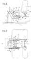
- the drawing shows a device 1 for handling a chassis of sofa 2 during the dressing of the latter.
- This chassis 2 comprises in its lower part two longitudinal and parallel battens referenced respectively 3 and 4.
- the device 1 includes in particular a telescopic upright 5, of adjustable height, which includes a base 6 for its fixing on the floor 7. At the upper end of the upright 5 is pivotally mounted around a horizontal axis 8 a shaft 9, at the free ends of which are fixed two parallel arms 10 and 11.
- the shaft 9 is rotated by a motor, hydraulic, pneumatic or electric controlled by control means known per se and not shown in the drawing, this motor accommodating for example inside the 5 upright.
- the extension of the amount 5 can be made under the order of the same means of ordered.
- This cradle 13 essentially comprises two longitudinal members 14, 15, arranged above the arms 10, 11 and connected by a first crosspiece 16 parallel to the pivot axes 8 and 12.
- the side members 14, 15 have ears 17 on their underside for mounting pivoting on the free ends of the arms 10, 11.
- Cylinders synchronized control 18 are mounted inside the arms 10, 11, and the rods 19 of these jacks 18 are articulated on the ears 17 in order to allow the cradle 13 to pivot about the axis 12 under the action control means.
- the side members 14 and 15 can advantageously be made up by synchronized cylinder cylinders, the rods 20, 21 of which their end a second crosspiece 22 which can be brought together or move away at the request of the first cross 16.
- the first crosspiece 16 carries two parallel bars 23, 24, inclined in the opposite direction to the cylinder rods 20, 21, and which have at their free ends fixed clamps 25 intended for grab the cleat 3 of the chassis 2.
- the second crosspiece 22 includes also two parallel bars 26, 27 perpendicular to the plane general of the cradle 13 and which have movable clamps 28 intended to grip the cleat 4 of the chassis 2.
- Each of the fixed clamps 25 or mobile 28 has two superimposed jaws 29, 30 which extend perpendicular to from one face of the bars 23, 24, 26, 27, this face forming a wall stop for one of the cleats 3, 4.
- the jaw 29 is constituted by a fixed or welded plate on the corresponding bar, while the second jaw 30 is formed by a tongue integral with a slide 31, movable mounted on the corresponding bar and likely to be immobilized on this last by locking / unlocking means 32 of the screw-nut type by example.
- the fixed clamps 25 and the movable clamps 28 are arranged above of the general plan of the cradle 13, and the jaws 29, 30 of the clamps fixed 25 are directed to one side of the chassis 2, while the movable jaws 29, 30 of the grippers are directed towards the other side of the chassis 2.
- the means for gripping the battens 3 and 4 of frame 2 can be adapted to several types of sofas.
- the spacing of the jaws 29 and 30 is adjusted according to the height cleats 3 and 4, while adjusting the output of the cylinder rods 20, 21 depending on the spacing of the brackets 3 and 4.
- the cylinder rods 20 and 21 To position a chassis 2 on the cradle 13, the cylinder rods 20 and 21, then the chassis 2 is positioned opposite the cradle 13, so that the cleat 3 is disposed between the jaws 29, 30 of the fixed clamps 25, these jaws having been previously positioned according to the thickness of the cleat 3. Then the cylinders of the side members 14 and 15 are actuated. The rods 20 and 22 come out of these cylinders until the jaws 29 and 30 of the movable clamps 28 grip the cleat 4 of the chassis 2. During this positioning, the telescopic upright 5 is in the low position, the arms 10 and 11 are positioned close to the ground 7 and the cradle 13 is at the horizontal.
- the arms 10 and 11 can pivot around the axis 8, from an angle to less than 90 ° and the cradle 13 can pivot around the axis 12 of a angle at least equal to 120 °.
- chassis 2 Once the chassis 2 is fixed on the cradle, it is possible to position the chassis in a plurality of positions by acting on the control means.
- Figures 4 to 7 show different positions of the chassis 2 on the cradle 13.
- Figure 4 shows the lower position of the upright 5 and the arm 10, 11 used for mounting the chassis 2 on the cradle 13.
- the Figure 5 shows the device 1 in the high position of the upright 5.
- the arms 10 and 11 are raised by 90 °. In the position shown in Figure 7, the arms 10 and 11 are in a position intermediate, the upright 5 is in the high position and the cradle 13 is tilted out to the maximum position.
- the different cylinders of the device 1 according to the invention can be hydraulic, pneumatic or screw-nut type actuated by electric motors.
- the control means can be constituted by push buttons provided in a case carried by the upright 5, or separate from the amount 5, or provided on a remote control which is equipped the operator.
Abstract
Description
L'invention concerne les postes d'habillage de canapés ou équivalents.The invention relates to dressing stations for sofas or equivalent.
L'habillage des châssis de canapé est réalisé actuellement en disposant le châssis sur une table, et le personnel manipule ce châssis au fur et à mesure de l'avancement de son habillage, sans l'aide de moyens de levage.The covering of the sofa frames is currently carried out in placing the chassis on a table, and staff manipulate the chassis as the dressing progresses, without the help of resources lifting.
L'habillage d'un canapé est donc une opération pénible, du fait notamment des manipulations demandées et du poids des objets à habiller.Dressing a sofa is therefore a painful operation, because in particular the manipulations requested and the weight of the objects to be dress.
Il existe ainsi un besoin de pourvoir les postes d'habillage de canapés ou équivalents d'un dispositif de support et de manutention du châssis au cours de son habillage.There is thus a need to fill the dressing stations of sofas or equivalent of a support and handling device for the chassis during its dressing.
L'invention concerne donc un dispositif de support et de manutention d'un objet tel qu'un châssis de canapé, au cours de son habillage, cet objet comportant au moins deux tasseaux parallèles.The invention therefore relates to a support and handling of an object such as a sofa frame, during its covering, this object comprising at least two parallel battens.
Selon l'invention ce dispositif est caractérisé par le fait qu'il
comporte :
Grâce à cette structure, lorsque les moyens de préhension agrippent les tasseaux de l'objet à habiller, il est possible de positionner l'objet à habiller, dans la position angulaire souhaitée et à la hauteur voulue au moins d'un côté et au-dessus du montant par actionnement des moyens de commande.Thanks to this structure, when the gripping means grip the cleats of the object to be dressed, it is possible to position the object to be dressed, in the desired angular position and at the height desired at least on one side and above the upright by actuation control means.
Les moyens de préhension agrippent les tasseaux par le dessous de l'objet à habiller.The gripping means grip the cleats from below of the object to be dressed.
Afin de pouvoir s'adapter à plusieurs types d'objets à habiller, les moyens de préhension sont avantageusement réglables pour s'adapter aux divers écartements de tasseaux. In order to be able to adapt to several types of objects to be dressed, the gripping means are advantageously adjustable to adapt to the various spacings of cleats.
Selon un mode de réalisation avantageux, les moyens de
préhension comportent :
Avantageusement, l'écartement des deux mâchoires des pinces est également réglable pour s'adapter aux différentes dimensions de tasseaux.Advantageously, the spacing of the two jaws of the pliers is also adjustable to adapt to the different dimensions of cleats.
De préférence, chaque pince comporte une barre dont une face constitue la butée de tasseau, une première languette fixée sur la barre et formant une mâchoire fixe, un coulisseau monté mobile sur ladite barre et présentant une deuxième languette formant la mâchoire mobile, et des moyens de blocage et déblocage du coulisseau sur la barre.Preferably, each clamp has a bar, one face of which constitutes the cleat stop, a first tab fixed on the bar and forming a fixed jaw, a slide mounted mobile on said bar and having a second tongue forming the movable jaw, and blocking and unblocking means of the slide on the bar.
De manière avantageuse, le montant vertical est réglable en hauteur, et le réglage en hauteur du montant vertical est réalisé par les moyens de commande.Advantageously, the vertical upright is adjustable in height, and the vertical upright is adjusted by the control means.
D'autres avantages et caractéristiques de l'invention ressortiront à
la lecture de la description suivante faite à titre d'exemple et en
référence au dessin annexé dans lequel :
Le dessin montre un dispositif 1 pour la manutention d'un châssis
de canapé 2 au cours de l'habillage de ce dernier. Ce châssis 2 comporte
dans sa partie inférieure deux tasseaux longitudinaux et parallèles
référencés respectivement 3 et 4.The drawing shows a
Le dispositif 1 comporte notamment un montant 5 télescopique,
de hauteur réglable, qui comporte une embase 6 pour sa fixation sur le
sol 7. A l'extrémité supérieure du montant 5 est monté pivotant autour
d'un axe horizontal 8 un arbre 9, aux extrémités libres duquel sont fixés
deux bras parallèles 10 et 11. L'arbre 9 est entraíné en rotation par un
moteur, hydraulique, pneumatique ou électrique commandé par des
moyens de commande connus en soi et non représentés sur le dessin, ce
moteur logeant par exemple à l'intérieur du montant 5. L'extension du
montant 5 peut être effectuée sous la commande des mêmes moyens de
commande.The
Aux extrémités libres des bras parallèles 10 et 11, est monté
pivotant autour d'un axe horizontal 12 parallèle à l'axe de pivotement 8
des bras 10 et 11 un berceau 13.At the free ends of the
Ce berceau 13 comporte essentiellement deux longerons 14, 15,
disposés au-dessus des bras 10, 11 et reliés par une première traverse
16 parallèle aux axes de pivotement 8 et 12. Les longerons 14, 15
présentent sur leur face inférieure des oreilles 17 pour leur montage
pivotant sur les extrémités libres des bras 10, 11. Des vérins de
commande synchronisés 18 sont montés à l'intérieur des bras 10, 11, et
les tiges 19 de ces vérins 18 sont articulées sur les oreilles 17 afin de
permettre le pivotement du berceau 13 autour de l'axe 12 sous l'action
des moyens de commande.This
Les longerons 14 et 15 peuvent être avantageusement constitués
par des cylindres de vérins synchronisés dont les tiges 20, 21 portent à
leur extrémité une deuxième traverse 22 que l'on peut rapprocher ou
éloigner à la demande de la première traverse 16.The
La première traverse 16 porte deux barres parallèles 23, 24,
inclinées dans le sens opposé aux tiges de vérins 20, 21, et qui
comportent à leurs extrémités libres des pinces fixes 25 destinées à
agripper le tasseau 3 du châssis 2.The
De la même manière, la deuxième traverse 22 comporte
également deux barres parallèles 26, 27 perpendiculaires au plan
général du berceau 13 et qui comportent des pinces mobiles 28
destinées à agripper le tasseau 4 du châssis 2.Similarly, the
Chacune des pinces fixes 25 ou mobiles 28 comporte deux
mâchoires superposées 29, 30 qui s'étendent perpendiculairement à
partir d'une face des barres 23, 24, 26, 27, cette face formant une paroi
de butée pour l'un des tasseaux 3, 4.Each of the
La mâchoire 29 est constituée par une plaquette fixée ou soudée
sur la barre correspondante, tandis que la deuxième mâchoire 30 est
formée par une languette solidaire d'un coulisseau 31, montée mobile
sur la barre correspondante et susceptible d'être immobilisée sur cette
dernière par des moyens de blocage/déblocage 32 du type vis-écrou par
exemple.The
Les pinces fixes 25 et les pinces mobiles 28 sont disposées au-dessus
du plan général du berceau 13, et les mâchoires 29, 30 des pinces
fixes 25 sont dirigées vers un côté du châssis 2, tandis que les
mâchoires 29, 30 des pinces mobiles sont dirigées vers l'autre côté du
châssis 2.The
Grâce à cette disposition, les moyens de préhension des tasseaux
3 et 4 du châssis 2 peuvent être adaptés à plusieurs types de canapés.
On règle l'écartement des mâchoires 29 et 30 en fonction de la hauteur
des tasseaux 3 et 4, tandis qu'on règle la sortie des tiges de vérins 20, 21
en fonction de l'écartement des tasseaux 3 et 4.Thanks to this arrangement, the means for gripping the battens
3 and 4 of
Pour positionner un châssis 2 sur le berceau 13, on rétracte les
tiges de vérins 20 et 21, puis on positionne le châssis 2 en regard du
berceau 13, de telle manière que le tasseau 3 soit disposé entre les
mâchoires 29, 30 des pinces fixes 25, ces mâchoires ayant été
préalablement positionnées en fonction de l'épaisseur du tasseau 3.
Ensuite on met en action les vérins des longerons 14 et 15. Les tiges 20
et 22 sortent de ces vérins jusqu'à ce que les mâchoires 29 et 30 des
pinces mobiles 28 agrippent le tasseau 4 du châssis 2. Durant ce
positionnement, le montant télescopique 5 est dans la position basse, les
bras 10 et 11 sont positionnés près du sol 7 et le berceau 13 est à
l'horizontal.To position a
Les bras 10 et 11 peuvent pivoter autour de l'axe 8, d'un angle au
moins égal à 90° et le berceau 13 peut pivoter autour de l'axe 12 d'un
angle au moins égal à 120°. The
Une fois que le châssis 2 est fixé sur le berceau, il est possible de
positionner le châssis dans une pluralité de positions en agissant sur le
moyens de commande.Once the
Le figures 4 à 7 montrent différentes positions du châssis 2 sur le
berceau 13. La figure 4 montre la position basse du montant 5 et des
bras 10, 11 utilisée pour le montage du châssis 2 sur le berceau 13. La
figure 5 montre le dispositif 1 dans la position haute du montant 5. Sur
la figure 6 les bras 10 et 11 sont relevés de 90°. Dans la position
représentée sur la figure 7, les bras 10 et 11 sont dans une position
intermédiaire, le montant 5 est dans la position haute et le berceau 13
est basculé vers l'extérieur dans la position maximum.Figures 4 to 7 show different positions of the
Sur les figures 4 à 7, les tiges de vérins 20, 21 sont dans une
position d'extension , du fait que les tasseaux 3 et 4 sont fortement
écartés l'un de l'autre. Sur la figure 8 on a représenté un châssis 2 dans
lequel les tasseaux 3 et 4 sont plus rapprochés, les tiges de vérin 20, 21
sont dans ce cas rétractées.In Figures 4 to 7, the
Les différents vérins du dispositif 1 selon l'invention peuvent être
hydrauliques, pneumatiques ou du type vis-écrou actionnés par des
moteurs électriques. Les moyens de commande peuvent être constitués
par des butons poussoirs prévus dans un boítier porté par le montant 5,
ou séparé du montant 5, ou prévus sur une télécommande dont est
équipé l'opérateur.The different cylinders of the
Claims (5)
Applications Claiming Priority (2)
| Application Number | Priority Date | Filing Date | Title |
|---|---|---|---|
| FR9700762 | 1997-01-24 | ||
| FR9700762A FR2758809A1 (en) | 1997-01-24 | 1997-01-24 | CANVAS OR EQUIVALENT COVERING STATION |
Publications (2)
| Publication Number | Publication Date |
|---|---|
| EP0855251A1 true EP0855251A1 (en) | 1998-07-29 |
| EP0855251B1 EP0855251B1 (en) | 2003-07-16 |
Family
ID=9502945
Family Applications (1)
| Application Number | Title | Priority Date | Filing Date |
|---|---|---|---|
| EP19980400086 Expired - Lifetime EP0855251B1 (en) | 1997-01-24 | 1998-01-19 | Work stand for upholstering of sofas or similar |
Country Status (3)
| Country | Link |
|---|---|
| EP (1) | EP0855251B1 (en) |
| DE (1) | DE69816349D1 (en) |
| FR (1) | FR2758809A1 (en) |
Cited By (4)
| Publication number | Priority date | Publication date | Assignee | Title |
|---|---|---|---|---|
| ES2277558A1 (en) * | 2005-12-27 | 2007-07-01 | Creaciones Confortables, S.L. | Improved machine for the partial machining of sofas, armchairs and similar |
| CN105108472A (en) * | 2015-09-24 | 2015-12-02 | 北京动力机械研究所 | Engine assembling device capable of continuously rotating |
| EP3187458A1 (en) * | 2015-12-28 | 2017-07-05 | Intelmec Ingenieria, S.L. | Device for supporting and handling of an object to be upholstered |
| FR3052175A1 (en) * | 2016-06-03 | 2017-12-08 | Solsin | DEVICE FOR MODIFYING THE HEIGHT OF THE WORK FLOOR OF AN OPERATOR BEFORE A PRODUCTION LINE |
Citations (6)
| Publication number | Priority date | Publication date | Assignee | Title |
|---|---|---|---|---|
| US2763053A (en) * | 1955-06-09 | 1956-09-18 | Wisconsin Hydraulics Inc | Universal work positioners |
| US2835964A (en) * | 1956-07-27 | 1958-05-27 | Fusarc Ltd | Manipulators for supporting work for welding or other operations |
| DE2903046A1 (en) * | 1978-01-30 | 1979-08-09 | Hultdins Verkstads Ab | Welding operation workpiece positioner - has telescopic column on base with head carrying detachable cantilevered holding device |
| US4221368A (en) * | 1978-07-31 | 1980-09-09 | Channel Chelsey B | Rotatable, tiltable and expandable upholstery work table |
| US4479632A (en) * | 1982-05-05 | 1984-10-30 | Mcintire Ray G | Dolly for an automotive engine |
| US4767109A (en) * | 1987-03-26 | 1988-08-30 | Raketich Milton F | Positioning apparatus |
-
1997
- 1997-01-24 FR FR9700762A patent/FR2758809A1/en not_active Withdrawn
-
1998
- 1998-01-19 DE DE69816349T patent/DE69816349D1/en not_active Expired - Lifetime
- 1998-01-19 EP EP19980400086 patent/EP0855251B1/en not_active Expired - Lifetime
Patent Citations (6)
| Publication number | Priority date | Publication date | Assignee | Title |
|---|---|---|---|---|
| US2763053A (en) * | 1955-06-09 | 1956-09-18 | Wisconsin Hydraulics Inc | Universal work positioners |
| US2835964A (en) * | 1956-07-27 | 1958-05-27 | Fusarc Ltd | Manipulators for supporting work for welding or other operations |
| DE2903046A1 (en) * | 1978-01-30 | 1979-08-09 | Hultdins Verkstads Ab | Welding operation workpiece positioner - has telescopic column on base with head carrying detachable cantilevered holding device |
| US4221368A (en) * | 1978-07-31 | 1980-09-09 | Channel Chelsey B | Rotatable, tiltable and expandable upholstery work table |
| US4479632A (en) * | 1982-05-05 | 1984-10-30 | Mcintire Ray G | Dolly for an automotive engine |
| US4767109A (en) * | 1987-03-26 | 1988-08-30 | Raketich Milton F | Positioning apparatus |
Cited By (6)
| Publication number | Priority date | Publication date | Assignee | Title |
|---|---|---|---|---|
| ES2277558A1 (en) * | 2005-12-27 | 2007-07-01 | Creaciones Confortables, S.L. | Improved machine for the partial machining of sofas, armchairs and similar |
| WO2007074189A1 (en) * | 2005-12-27 | 2007-07-05 | Creaciones Confortables, S.L. | Improved machine for the partial machining of sofas, armchairs and similar |
| CN105108472A (en) * | 2015-09-24 | 2015-12-02 | 北京动力机械研究所 | Engine assembling device capable of continuously rotating |
| EP3187458A1 (en) * | 2015-12-28 | 2017-07-05 | Intelmec Ingenieria, S.L. | Device for supporting and handling of an object to be upholstered |
| WO2017114626A1 (en) * | 2015-12-28 | 2017-07-06 | Intelmec Ingeniería, S.L. | Device for supporting and handling of an object to be upholstered |
| FR3052175A1 (en) * | 2016-06-03 | 2017-12-08 | Solsin | DEVICE FOR MODIFYING THE HEIGHT OF THE WORK FLOOR OF AN OPERATOR BEFORE A PRODUCTION LINE |
Also Published As
| Publication number | Publication date |
|---|---|
| FR2758809A1 (en) | 1998-07-31 |
| DE69816349D1 (en) | 2003-08-21 |
| EP0855251B1 (en) | 2003-07-16 |
Similar Documents
| Publication | Publication Date | Title |
|---|---|---|
| EP0179712B1 (en) | Wheeled stretcher with supporting surface adaptable in height | |
| FR2628405A1 (en) | HANDLING APPARATUS FOR GRIPPING AND MOVING OBJECTS | |
| EP0451061A1 (en) | Remote-controlled motorized load engaging device | |
| FR2605619A1 (en) | REPLIABLE MACHINE FOR HANDLING AND LIFTING LOADS | |
| EP0855251B1 (en) | Work stand for upholstering of sofas or similar | |
| FR2494617A1 (en) | UNIVERSAL ROBOT | |
| FR3071209A1 (en) | LONGITUDINAL CONSTRUCTION ELEMENT HANDLING SYSTEM, HANDLING VEHICLE EQUIPPED WITH SUCH A SYSTEM | |
| BE1010411A7 (en) | Automatic operation multiple hedge clipper support truck | |
| EP0100926B1 (en) | Material handling vehicle with an orientable arm and incorporated stabiliser frame | |
| FR2601105A1 (en) | POSITIONING DEVICE FOR THE TRANSPORT OF OBJECTS ALONG A TRAVEL PATH INCLUDING SEVERAL DIRECTIONS OF TRANSPORT | |
| FR3004480A1 (en) | WORKABLE FOLDING STRUCTURE INTEGRATING INTEGRATING A DEVICE FOR AIDING THE FOLDING OF AN AWNING | |
| FR2689073A1 (en) | Vehicle roof elongated load carrier, e.g. for ladder - comprises support which is raised or lowered by hydraulic cylinder or electric motor | |
| CA2251018C (en) | Device for the transfer of a load by thrust and traction in the same plan | |
| FR2541921A1 (en) | HANDLING DEVICE FOR WORKING REMOTE CONTROL WITH OPERATING MEANS | |
| FR2822103A1 (en) | Multi-position painting support comprises frame on which canvas can be stretched carried by adjustable horizontal arm and vertical support | |
| FR2720761A1 (en) | Laundry folding assembly | |
| FR2557003A1 (en) | Transfer mechanism, particularly for a robot | |
| FR2593201A1 (en) | Kerbstone-laying machine | |
| WO2002078155A1 (en) | Motorised pliers for flanging winding bars | |
| FR2466427A1 (en) | CRANE, INCLUDING CRANE OF LARGE DIMENSIONS | |
| FR2698540A1 (en) | Wheelchair structure. | |
| FR2557551A1 (en) | Automatic clamp for the handling and lifting of loads. | |
| FR2626865A1 (en) | Cradle for telescopic boom of lifting machine | |
| FR2678165A1 (en) | Device for lifting individuals | |
| FR2572377A1 (en) | LIFT DEVICE FOR LOADERS OF AGRICULTURAL TRACTORS |
Legal Events
| Date | Code | Title | Description |
|---|---|---|---|
| PUAI | Public reference made under article 153(3) epc to a published international application that has entered the european phase |
Free format text: ORIGINAL CODE: 0009012 |
|
| AK | Designated contracting states |
Kind code of ref document: A1 Designated state(s): BE CH DE ES FR GB GR IT LI LU PT |
|
| AX | Request for extension of the european patent |
Free format text: AL;LT;LV;MK;RO;SI |
|
| 17P | Request for examination filed |
Effective date: 19990128 |
|
| AKX | Designation fees paid |
Free format text: AT BE CH DE DK ES FI FR GB GR LI |
|
| RBV | Designated contracting states (corrected) |
Designated state(s): AT BE CH DE DK ES FI FR GB GR LI |
|
| RBV | Designated contracting states (corrected) |
Designated state(s): BE CH DE ES FR GB GR IT LI LU PT |
|
| 17Q | First examination report despatched |
Effective date: 20010903 |
|
| GRAG | Despatch of communication of intention to grant |
Free format text: ORIGINAL CODE: EPIDOS AGRA |
|
| GRAG | Despatch of communication of intention to grant |
Free format text: ORIGINAL CODE: EPIDOS AGRA |
|
| GRAH | Despatch of communication of intention to grant a patent |
Free format text: ORIGINAL CODE: EPIDOS IGRA |
|
| GRAH | Despatch of communication of intention to grant a patent |
Free format text: ORIGINAL CODE: EPIDOS IGRA |
|
| GRAA | (expected) grant |
Free format text: ORIGINAL CODE: 0009210 |
|
| AK | Designated contracting states |
Designated state(s): BE CH DE ES FR GB GR IT LI LU PT |
|
| PG25 | Lapsed in a contracting state [announced via postgrant information from national office to epo] |
Ref country code: IT Free format text: LAPSE BECAUSE OF FAILURE TO SUBMIT A TRANSLATION OF THE DESCRIPTION OR TO PAY THE FEE WITHIN THE PRESCRIBED TIME-LIMIT;WARNING: LAPSES OF ITALIAN PATENTS WITH EFFECTIVE DATE BEFORE 2007 MAY HAVE OCCURRED AT ANY TIME BEFORE 2007. THE CORRECT EFFECTIVE DATE MAY BE DIFFERENT FROM THE ONE RECORDED. Effective date: 20030716 Ref country code: GB Free format text: LAPSE BECAUSE OF FAILURE TO SUBMIT A TRANSLATION OF THE DESCRIPTION OR TO PAY THE FEE WITHIN THE PRESCRIBED TIME-LIMIT Effective date: 20030716 |
|
| REG | Reference to a national code |
Ref country code: GB Ref legal event code: FG4D Free format text: NOT ENGLISH |
|
| REG | Reference to a national code |
Ref country code: CH Ref legal event code: EP |
|
| REF | Corresponds to: |
Ref document number: 69816349 Country of ref document: DE Date of ref document: 20030821 Kind code of ref document: P |
|
| PG25 | Lapsed in a contracting state [announced via postgrant information from national office to epo] |
Ref country code: GR Free format text: LAPSE BECAUSE OF FAILURE TO SUBMIT A TRANSLATION OF THE DESCRIPTION OR TO PAY THE FEE WITHIN THE PRESCRIBED TIME-LIMIT Effective date: 20031016 |
|
| PG25 | Lapsed in a contracting state [announced via postgrant information from national office to epo] |
Ref country code: DE Free format text: LAPSE BECAUSE OF FAILURE TO SUBMIT A TRANSLATION OF THE DESCRIPTION OR TO PAY THE FEE WITHIN THE PRESCRIBED TIME-LIMIT Effective date: 20031017 |
|
| PG25 | Lapsed in a contracting state [announced via postgrant information from national office to epo] |
Ref country code: ES Free format text: LAPSE BECAUSE OF FAILURE TO SUBMIT A TRANSLATION OF THE DESCRIPTION OR TO PAY THE FEE WITHIN THE PRESCRIBED TIME-LIMIT Effective date: 20031027 |
|
| PG25 | Lapsed in a contracting state [announced via postgrant information from national office to epo] |
Ref country code: PT Free format text: LAPSE BECAUSE OF FAILURE TO SUBMIT A TRANSLATION OF THE DESCRIPTION OR TO PAY THE FEE WITHIN THE PRESCRIBED TIME-LIMIT Effective date: 20031216 |
|
| GBV | Gb: ep patent (uk) treated as always having been void in accordance with gb section 77(7)/1977 [no translation filed] |
Effective date: 20030716 |
|
| PG25 | Lapsed in a contracting state [announced via postgrant information from national office to epo] |
Ref country code: LU Free format text: LAPSE BECAUSE OF NON-PAYMENT OF DUE FEES Effective date: 20040119 |
|
| PG25 | Lapsed in a contracting state [announced via postgrant information from national office to epo] |
Ref country code: LI Free format text: LAPSE BECAUSE OF NON-PAYMENT OF DUE FEES Effective date: 20040131 Ref country code: CH Free format text: LAPSE BECAUSE OF NON-PAYMENT OF DUE FEES Effective date: 20040131 Ref country code: BE Free format text: LAPSE BECAUSE OF NON-PAYMENT OF DUE FEES Effective date: 20040131 |
|
| PLBE | No opposition filed within time limit |
Free format text: ORIGINAL CODE: 0009261 |
|
| STAA | Information on the status of an ep patent application or granted ep patent |
Free format text: STATUS: NO OPPOSITION FILED WITHIN TIME LIMIT |
|
| 26N | No opposition filed |
Effective date: 20040419 |
|
| BERE | Be: lapsed |
Owner name: *UNIVERSITE DE BORDEAUX II Effective date: 20040131 Owner name: ETS *CAPDEVIELLE & FILS S.A. Effective date: 20040131 Owner name: CABINET D'ETUDES *DARZACQ-BRIOLET Effective date: 20040131 |
|
| REG | Reference to a national code |
Ref country code: CH Ref legal event code: PL |
|
| PGFP | Annual fee paid to national office [announced via postgrant information from national office to epo] |
Ref country code: FR Payment date: 20060130 Year of fee payment: 9 |
|
| REG | Reference to a national code |
Ref country code: FR Ref legal event code: ST Effective date: 20070930 |
|
| PG25 | Lapsed in a contracting state [announced via postgrant information from national office to epo] |
Ref country code: FR Free format text: LAPSE BECAUSE OF NON-PAYMENT OF DUE FEES Effective date: 20070131 |