EP0854351B1 - A laser survey instrument - Google Patents
A laser survey instrument Download PDFInfo
- Publication number
- EP0854351B1 EP0854351B1 EP98300434A EP98300434A EP0854351B1 EP 0854351 B1 EP0854351 B1 EP 0854351B1 EP 98300434 A EP98300434 A EP 98300434A EP 98300434 A EP98300434 A EP 98300434A EP 0854351 B1 EP0854351 B1 EP 0854351B1
- Authority
- EP
- European Patent Office
- Prior art keywords
- tilt
- object reflector
- reflection
- laser
- light beam
- Prior art date
- Legal status (The legal status is an assumption and is not a legal conclusion. Google has not performed a legal analysis and makes no representation as to the accuracy of the status listed.)
- Expired - Lifetime
Links
- 230000001678 irradiating effect Effects 0.000 claims description 13
- 238000001514 detection method Methods 0.000 claims description 11
- 238000005259 measurement Methods 0.000 claims description 2
- 230000010287 polarization Effects 0.000 description 49
- 230000003287 optical effect Effects 0.000 description 15
- 238000010586 diagram Methods 0.000 description 6
- 230000003028 elevating effect Effects 0.000 description 3
- 238000000034 method Methods 0.000 description 3
- 230000007246 mechanism Effects 0.000 description 2
- 230000001133 acceleration Effects 0.000 description 1
- 230000008859 change Effects 0.000 description 1
- 238000006243 chemical reaction Methods 0.000 description 1
- 238000010276 construction Methods 0.000 description 1
- 230000001419 dependent effect Effects 0.000 description 1
- 230000006870 function Effects 0.000 description 1
- 239000011521 glass Substances 0.000 description 1
- 230000008569 process Effects 0.000 description 1
- 230000004044 response Effects 0.000 description 1
- 230000000007 visual effect Effects 0.000 description 1
Images


Classifications
-
- G—PHYSICS
- G01—MEASURING; TESTING
- G01C—MEASURING DISTANCES, LEVELS OR BEARINGS; SURVEYING; NAVIGATION; GYROSCOPIC INSTRUMENTS; PHOTOGRAMMETRY OR VIDEOGRAMMETRY
- G01C15/00—Surveying instruments or accessories not provided for in groups G01C1/00 - G01C13/00
- G01C15/002—Active optical surveying means
- G01C15/004—Reference lines, planes or sectors
Definitions
- the present invention relates to a laser survey instrument, by which it is possible to form a measurement plane, in particular an arbitrary tilt setting plane tilted by a given angle with respect to a horizontal reference plane in addition to a horizontal reference plane, by using a laser beam.
- a laser survey instrument is used to replace an optical levelling device.
- Both visible light and invisible light are used as the irradiating laser beam.
- visible light visibility is inferior under sunlight, and it is mostly used for indoor applications such as positioning of window frames or ceiling assembly during construction or reconstruction of a building.
- invisible light a photoelectric conversion photodetector is employed on the light receiving side, and the laser survey instrument can be used for both indoor and outdoor applications. In outdoor applications, it is used to form a reference plane for foundations of buildings or for ground levelling work.
- tilted ceilings are designed in many new buildings and a tilted reference plane or a tilted reference line is required for setting-out operation, for example, to mount indoor lights to suit the ceiling surface or to install a handrail along a staircase.
- the conventional laser survey instrument as described above is primarily designed to form a horizontal reference plane or a horizontal reference line, and a tilted reference plane or a tilted reference line cannot be easily formed. For this reason, the conventional instrument is not suitable for outdoor work or indoor interior work of a building having a tilted portion. At present, it is not possible to provide high working accuracy when mounting indoor lights to suit a ceiling surface or installing a handrail along a staircase as described above, and there is a strong need for a laser survey instrument which can easily perform tilt settings and obtain a tilted reference plane and a tilted reference line.
- EP-A-727642 discloses a laser survey instrument having a main unit for emitting a laser beam to an object reflector for reflecting beam from the main unit back towards the main unit.
- the main unit has an emitter, a rotator and a tilting mechanism.
- the instrument is operable to detect the tilt direction of an object reflector and then the laser beam is tilted with respect to the horizontal in response to an operation-input value of tilt angle.
- the laser survey instrument may comprise a rotary irradiation system main unit and an object reflector, wherein said object reflector has reflection sectors divided into two or more, at least one of the reflection sectors has a reflection surface with a gradually changing shape
- said rotary irradiation system main unit comprises a light emitter for emitting a polarized irradiation light beam, a rotator for rotating and irradiating the polarized irradiation light beam toward the object reflector and for detecting an irradiating direction, a tilt setting unit for tilting a rotary irradiation plane of the polarized irradiation light beam, detecting means for detecting a polarized reflection light beam entering the rotary irradiation system main unit via said rotator and reflected from said object reflector, a reflection light detecting circuit for identifying the object reflector from output of the detecting means, and a control unit for tracing said object reflector by operating said tilt setting unit based on detecting condition of said reflection
- the laser survey instrument may further comprise a rotary irradiation system main unit and an object reflector, wherein said object reflector has reflection sectors divided into two or more, at least one of said reflection sectors is a polarization converting reflection sector, and at least one of said reflection sectors has a reflection surface with shape gradually changing
- said rotary irradiation system main unit comprises a light emitter for emitting a polarized irradiation light beam, a rotator for rotating and irradiating the polarized irradiation light beam toward the object reflector and for detecting an irradiating direction, a tilt setting unit for tilting a rotary irradiation plane of the polarized irradiation light beam, a first detecting means for detecting a direction of polarization different from that of the polarized irradiation light beam emitted from the rotary irradiation system among the polarized reflection light beam entering the rotary irradiation system main unit via said rotator and reflected
- the polarized irradiation light beam irradiated from the rotator may be circularly polarized light.
- a tilting direction of the tilt setting unit is selected, the polarized irradiation light beam is irradiated for reciprocal scanning at a predetermined angle around the selected tilting direction, said control unit traces the object reflector based on the detecting condition of the reflection light detecting circuit and tilts the rotation plane of said polarized irradiation light beam.
- Two tilting directions can be set by setting another tilting direction within a predetermined time after the setting of a first tilting direction.
- a tilt angle is set by holding the object reflector for a predetermined duration of time.
- All of the reflection sectors of the object reflector may be polarization maintaining reflection sectors, which reflect light as a polarized reflection light beam, maintaining the direction of polarization of the polarized irradiation light beam. All of the reflection sectors of the object reflector may be polarization converting reflection sectors, which reflect light as a polarized reflection light beam, converting the direction of polarization of the polarized irradiation light beam.
- At least one of the reflection sectors of the object reflector is a polarization converting reflection sector, which reflects light as a polarized reflection light beam, converting the direction of polarization of the polarized irradiation light beam, and at least one of the reflection sectors is a polarization maintaining reflection sector, which reflects light as a polarized reflection light beam, maintaining direction of polarization of the polarized irradiation light beam.
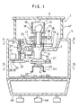
- a recessed portion 6 in truncated conical shape is formed, and a support seat 7 is provided at the center of the recessed portion 6.
- the support seat 7 is designed in such a manner that a projection 9 protruding toward the center with a smooth tertiary curved surface is formed at each of three equally divided positions on an inner periphery of a circular through-hole 8.
- a laser projector 10 for emitting a laser beam is placed into the through-hole 8, and a head 11 of the laser projector 10 is engaged with and supported by the support seat 7.
- the lower portion of the head 11 has a spherical shape, and a spherical unit 11a thus formed is brought into contact with each of the three projections 9.
- the laser projector 10 can be tiltably supported in any direction desired with respect to a vertical line or axis.
- a motor seat 14 is provided on the head 11, and a scanning motor 15 is arranged on the motor seat 14.
- a driving gear 16 is engaged on an output shaft of the scanning motor 15.
- the driving gear 16 is engaged with a scanning gear 17 to be described later.
- On the head 11 of the laser projector 10, a mirror holder 13 is rotatably mounted via a bearing 12 being aligned with an axis of the laser projector 10.
- the scanning gear 17 is attached on the mirror holder 13 and is engaged with the driving gear 16 as described above so that the mirror holder 13 can be rotated around the vertical axis by the scanning motor 15.
- a pentagonal prism 18 is arranged on the mirror holder 13, and a laser beam emitted from the laser projector 10 is irradiated in a horizontal direction through a projection window 19.
- the scanning motor 15, the driving gear 16, the mirror holder 13, the pentagonal prism 18, etc. constitute a rotator 2.
- a first level sensor 20 and a second level sensor 21 for detecting a horizontal line or plane are provided below the laser projector 10.
- a tilting detector 23 is fixed.
- the tilt detector 23 is designed in the shape of an inverted cup, and a reflection mirror flange 22 is arranged on the periphery.
- optical sensors 24a, 24b, 24c and 24d are provided on the same circumference around the axis of the laser projector 10 when the casing 5 and the laser projector 10 are at a vertical position.
- a first tilting arm 25 and a second tilting arm 26 are extended in a horizontal direction and perpendicularly to each other. These are designed to penetrate the conical plane of the recessed portion 6 and are positioned inside the casing 5.
- engaging pins 27 and 28 are arranged on a tip of each of the first tilting arm 25 and the second tilting arm 26 respectively.
- the engaging pins 27 and 28 are cylindrical, and have axes that cross perpendicular to each other.
- the engaging pins 27 and 28 are positioned in such a manner that these axes are included within a plane, which passes through the spherical center of the spherical unit 11a.
- the engaging pin 27 movement in a horizontal direction is restricted, and it can be moved only in a vertical direction.
- the engaging pin 27 is slidably engaged in a guide groove extending in a vertical direction, or the engaging pin 27 is slidably pressed against a wall surface that extends in a vertical direction via resilient means such as a spring, etc.
- a first level adjusting motor 31 is mounted on the shelf plate 29, and a second level adjusting motor 32 is mounted on the shelf plate 30.
- a first driving gear 33 is engaged on a rotation shaft of the first level adjusting motor 31, and a second driving gear 34 is engaged on a rotation shaft of the second level adjusting motor 32.
- a first screw shaft 35 running perpendicularly to the engaging pin 27 and stretched between the ceiling of the casing 5 and the shelf plate 29 is rotatably arranged.
- a first driven gear 36 is mounted on the first screw shaft 35 and is engaged with the first driving gear 33.
- the first screw shaft 35 is screwed into a first slide nut 37, and a pin 38 is protruded from the first slide nut 37.
- the pin 38 is slidably abutted on the engaging pin 27.
- a second screw shaft 39 running perpendicularly to the engaging pin 28 and stretched between the ceiling of the casing 5 and the shelf plate 30 are rotatably arranged.
- a second driven gear 40 is engaged on the second screw shaft 39 and is engaged with the second driving gear 34.
- the second screw shaft 39 is screwed into a second slide nut 41, and a pin 42 is protruded from the second slide nut 41.
- the pin 42 is slidably abutted on the engaging pin 28.
- a spring receptacle 43 is arranged between the first screw shaft 35 and the second screw shaft 39, and a spring 44 is stretched between the spring receptacle 43 and the laser projector 10 so that the laser projector 10 is pushed in clockwise direction around the support seat 7 as shown in Fig. 1.
- reference numeral 45 represents a battery box to accommodate a battery for driving the laser survey instrument.
- the rotary irradiation system main unit 1 is mounted on a tripod (not shown) via screws 46 for levelling.
- Reference numeral 47 represents a glass window provided on the periphery of the mirror holder 13.
- Figure 4 is a block diagram that shows a tilting controller.
- Detection results of the first level sensor 20 and the second level sensor 21 are inputted to a first angle detecting circuit 51 and a second angle detecting circuit 52.
- a reference angle 50 (usually, the reference plane is horizontal and the reference angle is 0°) is set.
- Angular deviations are calculated in the first angle detecting circuit 51 and the second angle detecting circuit 52 respectively based on the reference angle 50.
- the angular deviation thus calculated is inputted to a first motor controller 53 and a second motor controller 54 respectively or to a computation controller 55.
- the computation controller 55 inputs a control signal such as rotating direction instruct signal, a speed control signal and a speed acceleration/deceleration signal, etc.
- the first motor controller 53 and the second motor controller 54 drive the first level adjusting motor 31 and the second level adjusting motor 32 respectively.
- the computation controller 55 controls the first level adjusting motor 31 and the second level adjusting motor 32 via the first motor controller 53 and the second motor controller 54 so that the deviation of the angular signals from the first angle detecting circuit 51 and the second angle detecting circuit 52 is turned to 0.
- the axis of the laser projector 10 is not aligned with a vertical line, and the first level sensor 20 and the second level sensor 21 are not at a horizontal position.
- the reference angle 50 is 0°
- angular deviation signals are issued from the first angle detecting circuit 51 and the second angle detecting circuit 52 to the computation controller 55.
- the computation controller 55 drives the first level adjusting motor 31 and the second level adjusting motor 32 in a desired direction via the first motor controller 53 and the second motor controller 54 so that each of the angular deviation signals is turned to 0.
- first level adjusting motor 31 When the first level adjusting motor 31 is driven, rotation of the first level adjusting motor 31 is transmitted to the first screw shaft 35 via the first driving gear 33 and the first driven gear 36, and the first slide nut 37 is moved up or down as the first screw shaft 35 is turned. Upward or downward movement of the first slide nut 37 is transmitted to the first tilting arm 25 via the pin 38 and the engaging pin 27, and the laser projector 10 is tilted.
- the engaging pin 27 is restricted from moving in a horizontal direction and can move only in a vertical direction. For this reason, a tilting direction of the laser projector 10 is restricted, and it is tilted around the axis of the engaging pin 28, which runs through the spherical center of the spherical unit 11a.
- the second level adjusting motor 32 is driven, the second screw shaft 39 is turned, and the engaging pin 28 is moved up or down via the pin 42.
- the movement of the engaging pin 27 in a horizontal direction is restricted by a groove (not shown), and its movement in a vertical direction is restricted by the pin 38 and the spring 44.
- the engaging pin 27 is allowed only to rotate around the axis of the engaging pin 27, which runs through the spherical center of the spherical unit 11a.
- the engaging pin 28 slides in an axial direction between the engaging pin 28 and the pin 42, and the engaging pin 28 is vertically displaced, and the laser projector 10 is tilted around the axis of the engaging pin 27.
- cross-section of the engaging pin 27 is in circular shape. Thus, tilting of the axis of the engaging pin 27 is not changed due to the rotation of the engaging pin 27.
- tilting operation by the level adjusting motors 31 and 32 exerts no influence on tilting axis of the other, i.e. on tilting of the axes of the engaging pins 27 and 28. Therefore, tilt adjusting operation of one axis can be performed independently from tilt adjusting operation of the other axis, and the tilt adjusting operation and control sequence relating to the tilt adjusting operation can be extremely simplified.
- the laser projector 10 Because the laser projector 10 is pushed in clockwise direction in Fig. 1 by the spring 44, the laser projector 10 accurately follows the movement of the first slide nut 37.
- the optical sensors 24a, 24b, 24c and 24d to prevent the movement of the adjusting mechanism (which comprises the first level adjusting motor 31, the second level adjusting motor 32, the first driving gear 33, the second driving gear 34, the first driven gear 36, the second driven gear 40, the first screw shaft 35, the second screw shaft 39, the first slide nut 37, the second slide nut 41, the first tilting arm 25, the second tilting arm 26, etc.) beyond the mechanical adjustment range.
- the limit of the mechanical adjustment range is reached, light emitted from one of the optical sensors 24a, 24b 24c or 24d is reflected by the reflection mirror flange 22 and is received by the optical sensor again, and it is detected that the limit of the mechanical adjustment range has been reached.
- the first level adjusting motor 31 and the second level adjusting motor 32 are stopped, or display is provided on a display unit (not shown) or alarm such as buzzer is issued to indicate that the limit of the mechanical adjustment range has been reached.
- the laser projector 10 With regard to tilting operation of the laser projector 10, the laser projector 10 is stably supported because the spherical unit 11a of the laser projector 10 is supported at 3 points by the projections 9. Because of the contact between the spherical unit 11a and the projections 9 with smooth curved surfaces, the laser projector 10 can be tilted in any tilling direction smoothly and freely, and the posture of the laser projector 10 can be easily adjusted. Detailed description on the tilting operation is not given here because it is the same as the leveling operation described above.
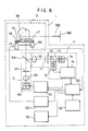
- the rotary irradiation system main unit 1 comprises a light emitter 3, a rotator 2, a reflection light detector 4, a control unit (CPU) 60, a light emitting element driving unit 61, a motor driving unit 62, and a control panel 63.
- the light emitter 3 is described.
- a collimator lens 66 On an optical axis of a laser diode or a visible laser diode 65, which emits a polarized irradiation light beam of linearly polarized light, a collimator lens 66, a first ⁇ /4 birefringence member 67, and a perforated mirror 68 are arranged in this order as seen from the laser diode 65.
- the polarized irradiation light beam of linearly polarized light emitted from the laser diode 65 is turned to a parallel beam by the collimator lens 66 and is converted to circularly polarized light by the first ⁇ /4 birefringence member 67.
- the circularly polarized irradiation light beam passes through the perforated mirror 68 and is irradiated to the rotator 2.
- the rotator 2 deflects an optical axis of the polarized irradiation light beam 100 emitted from the light emitter 3 by 90° and irradiates the light beam for scanning.
- a pentagonal prism 18 for deflecting the optical axis of the polarized irradiation light beam coming from the light emitter 3 is provided on the mirror holder 13, which is rotated around the optical axis of the polarized irradiation light beam.
- the mirror holder 13 is connected to a scanning motor 15 via a scanning gear 17 and a driving gear 16.
- the rotating condition of the mirror holder 13 is detected by an encoder 69, and a detection signal of the encoder 69 is inputted to the control unit (CPU) 60.
- the irradiated laser beam from the rotator 2 is reflected by an object reflector 80, and a polarized reflection light beam coming from the object reflector 80 enters the rotator 2.
- the polarized reflection light beam After entering the pentagonal prism 18, the polarized reflection light beam is deflected toward the perforated mirror 68, and the polarized reflection light beam enters the reflection light detector 4 through the perforated mirror 68.
- a condenser lens 70, a second ⁇ /4 birefringence member 71, a pinhole 72, a polarization beam splitter 73, and a first photoelectric converter 74 are arranged in this order as seen from the perforated mirror 68, and a second photoelectric converter 75 is arranged on the reflection optical axis of the polarization beam splitter 73. Outputs from the first photoelectric converter 74 and the second photoelectric converter 75 are inputted to a reflection light detecting circuit 76.
- the polarization beam splitter 73 splits the polarized reflection light beam entering the reflection light detector 4 and the light beam enters the first photoelectric converter 74 and the second photoelectric converter 75.
- the second ⁇ /4 birefringence member 71 and the polarization beam splitter 73 are arranged in such manner that the polarized irradiation light beam, emitted from the light emitter 3 and having the same direction of polarization as that of the polarized reflection beam returning to the main unit after passing through the ⁇ /4 birefringence member twice, is irradiated to the first photoelectric converter 74, and the polarized irradiation light beam emitted from the light emitter 3 and having the same direction of polarization as the polarized irradiation light beam is irradiated to the second photoelectric converter 75.
- control unit (CPU) 60 The control unit (CPU) 60.
- Instructions from an operator are inputted to the control unit (CPU) 60, via the control panel 63. Signals from the encoder 69 and the reflection light detector 4 are also inputted to the CPU 60.
- the position of the object reflector 80 and widths of a polarization converting reflection sector (to be described later) and a reflection layer (to be described later) of the object reflector 80 are detected, and rotation of the rotator 2 is controlled via the motor driving unit 62.
- the position on the object reflector 80 which is scanned is detected by the polarized irradiation light beam, and it is given as a scanning position signal.
- the signal from the control unit 60 is inputted to the computation controller 55, which drives in turn the level adjusting motors 31 and 32 via the motor controllers 53 and 54.
- the light emitting condition of the laser diode 65 is controlled according to the rotating condition of the rotator 2 via the light emitting element driving unit 61.
- the light emitting element driving unit 61 obtains a clock signal for pulse modulation from the reflection light detecting circuit 76 and performs pulse modulation of the polarized irradiation light beam emitted from the laser diode 65. This pulse modulation makes it possible to easily amplify the photodetection signal and to decrease noise level.
- the motor driving unit 62 controls rotation of the scanning motor 15 of the rotator 2 based on a rotating direction signal from the control unit 60 and controls scanning of the polarized irradiation light beam.
- the control panel 63 comprises tilting direction setting buttons 90a, 90b, 90c, and 90d for setting a tilting direction (an irradiating direction of the laser beam for reciprocal scanning at a desired angle), stop mode buttons 91a and 91b for fixing an irradiating direction of the laser beam and for setting it to stop mode for step feeding, rotary scanning speed setting buttons 92a and 92b, a power source button 93, a photodetector setting button 94, which switches the rotary scanning speed of the laser beam between the case where a photodetector is used and the case where a visual check is performed because the rotary scanning speed is different in both of the cases, and a manual button 95 for selecting automatic leveling or manual adjustment of the system.
- the setting status by the tilting direction setting buttons 90a, 90b, 90c and 90d is displayed by a light emitting diode 96
- battery consumption status of the rotary irradiation system main unit 1 is displayed by a light emitting diode 97
- selecting status of the photodetector by the photodetector setting button 94 is displayed by a light emitting diode 98
- automatic or manual selection status of the manual button 95 is displayed by a light emitting diode 99.
- the polarized irradiation light beam emitted from the laser diode 65 which is driven by the light emitting element driving unit 61, is modulated according to the clock signal from an oscillator (not shown).
- the linearly polarized irradiation light beam emitted from the laser diode 65 is turned to parallel beam by the collimator lens 66. Further, it is turned to circularly polarized irradiation light beam after passing through the first ⁇ /4 birefringence member 67.
- the circularly polarized irradiation light beam passes through the perforated mirror 68 and is deflected by an angle of 90° through the pentagonal prism 18 and is irradiated from the rotary irradiation system main unit 1.
- the pentagonal prism 18 is rotated by the scanning motor 15 via the driving gear 16 and the scanning gear 17. At first, the pentagonal prism 18 is rotated by total circumferential rotation, and the polarized irradiation light beam coming through the pentagonal prism 18 is irradiated for total circumferential scanning.
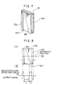
- a ⁇ /4 birefringence member in form of oblong tablet is attached along the left edge to form a polarization converting reflection sector 85a.
- a ⁇ /4 birefringence member of inverted triangular shape is attached at a position opposite to the polarization converting reflection sector 85a to have a reflection layer (polarization maintaining reflection sector) 84b in erected triangular shape therebetween, thus forming a polarization converting reflection sector 85b.
- a reflection layer (polarization maintaining reflection sector) 84a of oblong tablet shape is provided along the right edge.
- the object reflector 80 comprises polarization maintaining reflection sectors 84a and 84b and polarization converting reflection sectors 85a and 85b.
- the polarization reflection light beam reflected by the polarization maintaining reflection sectors 84a and 84b is circularly polarized light where polarization status of the incident polarized irradiation light beam is maintained, and the polarized reflection light beam reflected by the polarization converting reflection sectors 85a and 85b is circularly polarized light having phase deviated by ⁇ /2 with respect to the polarization status of the incident polarized irradiation light beam.
- the polarized reflection light beam reflected by the object reflector 80 and entering the rotator 2 is deflected by an angle of 90° by the pentagonal prism 18 and enters the perforated mirror 68, and the perforated mirror 68 irradiates the reflection light beam toward the condenser lens 70.
- the condenser lens 70 irradiates the reflection light beam as convergent light toward the second ⁇ /4 birefringence member 71, and the polarized reflection light beam, returning as circularly polarized light, is converted to linearly polarized light by the second ⁇ /4 birefringence member 71 and enters the pinhole 72.
- the polarized reflection light beam reflected by the polarization maintaining reflection sectors 84a and 84b has its phase by ⁇ /2 different from the phase of the polarized reflection light beam reflected by the polarization converting reflection sectors 85a and 85b.
- plane of polarization differs by 90° between the two polarized reflection light beams, which have been converted to linearly polarized light by the second ⁇ /4 birefringence member 71.
- the pinhole 72 plays a role to prevent this reflection light beam from entering the first photoelectric converter 74 and the second photoelectric converter 75. After passing through the pinhole 72, the polarized reflection light beam enters the polarization beam splitter 73.
- the polarization beam splitter 73 splits the light beam into polarized components, which run perpendicularly to each other. It allows the polarized reflection light beam to pass, which is the same as (but having direction of polarization varied by 180° from) the polarized irradiation light beam emitted from the laser diode 65 and reflects the polarized reflection light beam, which has direction of polarization by 90° different from that of the polarized irradiation light beam emitted from the laser diode 65. Both the first photoelectric converter 14 and the second photoelectric converter 75 receive the polarized reflection light beam thus split.
- the first photoelectric converter 74 and the second photoelectric converter 75 are designed to have the following photodetecting conditions: When the polarized reflection light beam reflected by the polarization converting reflection sectors 85a and 85b of the object reflector 80 enters the reflection light detector 4, it is designed in such manner that the amount of light entering the first photoelectric converter 74 is more than the amount of light entering the second photoelectric converter 75 because of the relationship between the second ⁇ /4 birefringence member 71 and the polarization beam splitter 73, and that when the polarized reflection light beam reflected by the polarization maintaining reflection sectors 84a and 84b of the object reflector 80 enters the reflection light detector 4, the amount of light entering the second photoelectric converter 75 is more than the amount of light entering the first photoelectric converter 74.
- an output signal from the reflection light detecting circuit 76 is as shown in Figure 8 (B).
- the center of the object reflector 80 can be detected.
- signal waveform is asymmetrical. Therefore, even when the laser beam scans the center of the object reflector 80, the scanning direction of the laser beam can be identified only from the output signal from the reflection light detecting circuit 76.
- the polarization maintaining reflection sector 84a and the polarization converting reflection sector 85a are formed on the edges of the polarization maintaining reflection sector 84b and the polarization converting reflection sector 85b, which are each triangular in shape.
- a vertical direction can be identified from the object reflector itself, when the rotary irradiation system main unit 1 is installed on a ceiling or a floor etc., it is possible to easily distinguish reflection light, which is reflected by the ceiling or floor surface and comes back.
- the polarization maintaining reflection sector 84b and the polarization converting reflection sector 85b in inverted triangular shape make it possible to easily identify the central position of the object reflector 80, while these reflection sectors may be designed in V-shape or inverted V-shape.
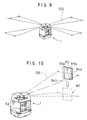
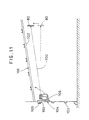
- the rotary irradiation system main unit 1 is installed, as shown in Fig. 11, for example, on upper portion of wall of a building 101 near ceiling 102 via a mounting stand 104.
- the mounting stand 104 has a clamp 105.
- the mounting stand 104 has an elevating table 106, which can be moved up or down to adjust the vertical position of the stand.
- the rotary irradiation system main unit 1 is fixed on the elevating table 106 using fixing means such as bolt.
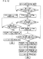
- the rotary irradiation system main unit 1 starts to perform the leveling operation as described above. It is operated in such manner that the polarized irradiation light beam 100 can be irradiated in a horizontal direction, and the polarized irradiation light beam 100 is rotated and irradiated in a horizontal direction.
- One of the tilting direction setting buttons 90a, 90b, 90c and 90d is pressed to set a first tilting direction.
- the first tilting direction thus set is stored in memory in the control unit 60.
- the polarized irradiation light beam 100 is irradiated toward the first tilting direction, and reciprocal scanning in fan-shaped is performed with the preset scanning angular range.
- the setting of tilting direction is completed.
- a second tilting direction is set by operating another tilting direction setting button within a predetermined time. Then, the second tilting direction thus set is stored in memory in the control unit 60 just like the first tilting direction. The second tilting direction is compared with the first tilting direction in the control unit 60. If both tilting directions agree with each other, the setting is cancelled. If the second tilting direction is different from the first tilting direction, tilt setting operation is performed on each of the tilting directions. Specifically, the polarized irradiation light beam 100 is irradiated toward the first tilting direction at first, and reciprocal scanning is performed within a preset angular scanning range.
- the tilt setting operation By the tilt setting operation, if t1 and t2 agree with each other, the polarized irradiation light beam 100 is irradiated in the second tilting direction after the predetermined time. Then, reciprocal scanning is performed within the preset angular scanning range, and the tilt setting is performed in the same way.
- the transfer between the tilt setting operation of the first tilting direction and the tilt setting operation of the second tilting direction may be automatically performed after the predetermined time has elapsed, or operator may operate button to transfer the operation.
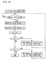
- the operator holds the object reflector 80 by hand and keeps it in the polarized irradiation light beam 100 so that the polarized irradiation light beam 100 is irradiated on the object reflector 80.
- the polarized irradiation light beam 100 scans across the object reflector 80 reciprocally, and reflection light from the object reflector 80 enters the rotary irradiation system main unit 1, and a photodetection signal from the reflection light detector 4 is outputted to the control unit 60.
- the object reflector 80 is set in a predetermined direction, e.g. in case an angle of elevation is to be set, it is moved up as shown in Fig. 10 and Fig. 11.
- the rotary irradiation system main unit 1 forces the polarized irradiation light beam 100 to trace the object reflector 80 and gives an angle of elevation to it.
- Angle of elevation or depression of the polarized irradiation light beam 100 is adjusted by tilting the laser projector 10, and tilting of the polarized irradiation light beam 100 based on the determination of the angle of elevation or depression with respect to a horizontal plane agrees with the tilting direction of the laser projector 10.
- the object reflector 80 is moved toward a position to be set and is held there for a predetermined time.
- the rotary irradiation system main unit 1 is operated in such a manner that the scanning position of the polarized irradiation light beam 100 is aligned with the center of the object reflector 80.
- a predetermined time has elapsed under this condition, it is judged that the tilt setting has been completed, and even when the object reflector 80 is removed, tile setting of the polarized irradiation light beam 100 is maintained at the same position.
- the polarized irradiation light beam 100 forms a reference plane by rotary irradiation in parallel to the ceiling 102. Based on this reference plane, an illuminating lamp is mounted, for example, in a fixed direction from the ceiling.
- the setting value of angle of elevation or depression is inputted to a reference angle 50 as shown in Fig. 4 after leveling.
- Outputs from the first angle detecting circuit 51 and the second angle detecting circuit 52 are inputted to the computation controller 55.
- the computation controller 55 drives the first level adjusting motor 31 and the second level adjusting motor 32 via the first motor controller 53 and the second motor controller 54 so that a detection angle from the first angle detecting circuit 51 and the second angle detecting circuit 52 is turned to the reference angle 50.
- the polarization maintaining reflection sectors 84a and 84b may be reflection surfaces, and the polarization converting reflection sectors 85a and 85b may be non-reflection surfaces.
- the width at the central position is considered as a known value, and if a comparison value is inputted, there is no need to compare photodetecting conditions from the two reflection sectors, and it is possible to detect the center of the object reflector by comparing the signal width (duration) obtained by the photodetection signal from one reflection sector with the comparison value.
- the computation controller 55 and the control unit 60 may be replaced with a single control unit, which has the same functions as these components.
- the tilting direction can be set by simply pressing the tilting direction setting button, and the setting of tilt angle can be completed by simply irradiating the polarized irradiation light beam on the object reflector and by moving it to a predetermined position. Accordingly, it is possible to easily set a tilting reference plane and a tilting reference line by extremely simplified working procedure.
Landscapes
- Physics & Mathematics (AREA)
- Engineering & Computer Science (AREA)
- General Physics & Mathematics (AREA)
- Radar, Positioning & Navigation (AREA)
- Remote Sensing (AREA)
- Optical Radar Systems And Details Thereof (AREA)
- Length Measuring Devices By Optical Means (AREA)
Applications Claiming Priority (4)
| Application Number | Priority Date | Filing Date | Title |
|---|---|---|---|
| JP2203497 | 1997-01-21 | ||
| JP22034/97 | 1997-01-21 | ||
| JP02203497A JP3710112B2 (ja) | 1997-01-21 | 1997-01-21 | レーザ測量機 |
| US09/003,960 US5946087A (en) | 1997-01-21 | 1998-01-07 | Laser survey instrument |
Publications (3)
| Publication Number | Publication Date |
|---|---|
| EP0854351A2 EP0854351A2 (en) | 1998-07-22 |
| EP0854351A3 EP0854351A3 (en) | 2000-03-01 |
| EP0854351B1 true EP0854351B1 (en) | 2006-05-17 |
Family
ID=26359193
Family Applications (1)
| Application Number | Title | Priority Date | Filing Date |
|---|---|---|---|
| EP98300434A Expired - Lifetime EP0854351B1 (en) | 1997-01-21 | 1998-01-21 | A laser survey instrument |
Country Status (3)
| Country | Link |
|---|---|
| US (1) | US5946087A (enExample) |
| EP (1) | EP0854351B1 (enExample) |
| JP (1) | JP3710112B2 (enExample) |
Cited By (1)
| Publication number | Priority date | Publication date | Assignee | Title |
|---|---|---|---|---|
| CN101535764B (zh) * | 2006-11-03 | 2013-01-16 | 特林布尔凯泽斯劳滕有限公司 | 倾斜度指示设备和方法 |
Families Citing this family (53)
| Publication number | Priority date | Publication date | Assignee | Title |
|---|---|---|---|---|
| JP3800271B2 (ja) * | 1997-09-30 | 2006-07-26 | 株式会社トプコン | レーザ測量機 |
| US6138367A (en) * | 1998-08-14 | 2000-10-31 | Trimble Navigation Limited | Tilt prediction for total station |
| SE513112C2 (sv) | 1998-11-10 | 2000-07-10 | Damalini Ab | Inriktningsorgan och förfarande |
| JP4317639B2 (ja) * | 2000-03-29 | 2009-08-19 | 株式会社トプコン | レーザ測量機 |
| JP4416925B2 (ja) | 2000-07-19 | 2010-02-17 | 株式会社トプコン | 位置測定設定システム及びそれに使用する受光センサ装置 |
| DE10054627C2 (de) * | 2000-11-03 | 2002-10-31 | Nestle & Fischer Gmbh & Co Kg | Vorrichtung zum Ausrichten eines von einem Rotationslaser erzeugten Laserstrahls |
| JP2002296031A (ja) * | 2001-03-30 | 2002-10-09 | Sokkia Co Ltd | レーザ測量機 |
| US7278218B2 (en) | 2003-06-18 | 2007-10-09 | Irwin Industrial Tool Company | Laser line generating device with swivel base |
| JP4870283B2 (ja) * | 2001-07-13 | 2012-02-08 | 株式会社トプコン | レーザ照準装置 |
| JP5000819B2 (ja) * | 2001-08-30 | 2012-08-15 | 株式会社トプコン | 回転レーザ装置 |
| JP3816807B2 (ja) * | 2002-01-21 | 2006-08-30 | 株式会社トプコン | 位置測定装置及びそれに使用する回転レーザ装置 |
| JP4228132B2 (ja) * | 2002-10-18 | 2009-02-25 | 株式会社トプコン | 位置測定装置 |
| JP2004212058A (ja) * | 2002-12-26 | 2004-07-29 | Topcon Corp | 作業位置測定装置 |
| CN2588326Y (zh) * | 2002-12-27 | 2003-11-26 | 南京泉峰国际贸易有限公司 | 激光标线器 |
| DE10325859B3 (de) * | 2003-06-06 | 2004-06-03 | Hilti Ag | Rotationsbaulaser |
| US7013570B2 (en) | 2003-06-18 | 2006-03-21 | Irwin-Industrial Tool Company | Stud finder |
| US7269907B2 (en) | 2003-07-01 | 2007-09-18 | Irwin Industrial Tool Company | Laser line generating device with swivel base |
| USD526587S1 (en) * | 2004-03-18 | 2006-08-15 | Black & Decker Inc. | Laser level |
| USD498687S1 (en) * | 2004-03-18 | 2004-11-23 | Black & Decker Inc. | Laser level |
| CN2718518Y (zh) * | 2004-06-18 | 2005-08-17 | 南京德朔实业有限公司 | 激光标线器 |
| US7266897B2 (en) * | 2004-06-21 | 2007-09-11 | Laserline Mfg., Inc. | Self-aligning, self plumbing baseline instrument |
| US7487596B2 (en) | 2004-06-25 | 2009-02-10 | Irwin Industrial Tool Company | Laser line projected on an edge of a surface |
| US7178250B2 (en) | 2004-07-21 | 2007-02-20 | Irwin Industrial Tool Company | Intersecting laser line generating device |
| DE102004053249B4 (de) | 2004-11-04 | 2006-08-17 | Hilti Ag | Baulaser mit neigbarem Umlenkmittel |
| DE102005000140A1 (de) | 2005-10-17 | 2007-04-19 | Hilti Ag | Neigungssteuerungsverfahren |
| JP4824384B2 (ja) * | 2005-10-25 | 2011-11-30 | 株式会社トプコン | レーザ測量機 |
| CN101078623B (zh) | 2006-05-26 | 2010-05-12 | 南京德朔实业有限公司 | 自水平激光标线装置及其控制方法 |
| US8060344B2 (en) * | 2006-06-28 | 2011-11-15 | Sam Stathis | Method and system for automatically performing a study of a multidimensional space |
| DE202006014576U1 (de) * | 2006-08-21 | 2008-01-03 | STABILA Messgeräte Gustav Ullrich GmbH | Schutzeinrichtung |
| ES2366054T3 (es) * | 2006-08-21 | 2011-10-14 | STABILA Messgeräte Gustav Ullrich GmbH | Dispositivo de protección. |
| CN201035148Y (zh) * | 2007-01-19 | 2008-03-12 | 南京德朔实业有限公司 | 激光测距仪 |
| CN201035149Y (zh) * | 2007-01-19 | 2008-03-12 | 南京德朔实业有限公司 | 激光测距仪 |
| US8238008B2 (en) * | 2008-06-09 | 2012-08-07 | Trimble Navigation Limited | Laser transmitter and method |
| DE102008041033A1 (de) * | 2008-08-06 | 2010-02-11 | Hilti Aktiengesellschaft | Rotationsbaulaser |
| DE202008008821U1 (de) | 2008-08-28 | 2010-02-11 | STABILA Messgeräte Gustav Ullrich GmbH | Laservorrichtung |
| JP5210783B2 (ja) * | 2008-09-30 | 2013-06-12 | 株式会社オーディオテクニカ | レーザ墨出し器 |
| US20100153457A1 (en) * | 2008-12-15 | 2010-06-17 | Grant Isaac W | Gestural Interface Device and Method |
| DE102009000350B3 (de) * | 2009-01-21 | 2010-08-19 | Trimble Jena Gmbh | Motorantriebsvorrichtung und Steuerverfahren für ein Vermessungsinstrument |
| JP5456532B2 (ja) * | 2010-03-25 | 2014-04-02 | 株式会社トプコン | 回転レーザ装置及び回転レーザシステム |
| JP5568363B2 (ja) * | 2010-04-22 | 2014-08-06 | 株式会社トプコン | レーザスキャナ |
| FR2966238A1 (fr) | 2010-10-13 | 2012-04-20 | Psp Outil | Niveau laser comprenant un module de detection de mouvement. |
| FR2966237A1 (fr) | 2010-10-13 | 2012-04-20 | Psp Outil | Indication angulaire sur une telecommande et mise en station rapide d'un niveau laser. |
| US8684632B2 (en) | 2010-12-08 | 2014-04-01 | Laserline Mfg., Inc. | Systems and methods for laying out and installing a solar panel array |
| DE102011079384B4 (de) | 2011-07-19 | 2013-09-26 | Trimble Jena Gmbh | Verfahren und Vorrichtung zum Bestimmen einer Qualität einer Getriebeanordnung aus mindestens zwei Getrieberädern |
| JP6173067B2 (ja) * | 2013-06-25 | 2017-08-02 | 株式会社トプコン | レーザ測量機 |
| JP6282074B2 (ja) * | 2013-09-30 | 2018-02-21 | 株式会社トプコン | レーザ測量システム |
| US10286308B2 (en) | 2014-11-10 | 2019-05-14 | Valve Corporation | Controller visualization in virtual and augmented reality environments |
| JP6498528B2 (ja) * | 2015-05-28 | 2019-04-10 | 株式会社トプコン | 測量装置 |
| JP6539501B2 (ja) * | 2015-05-28 | 2019-07-03 | 株式会社トプコン | 測量装置 |
| US10006768B2 (en) | 2016-03-15 | 2018-06-26 | Stanley Black & Decker Inc. | Laser level |
| DE102016107100A1 (de) * | 2016-04-18 | 2017-10-19 | Status Pro Maschinenmesstechnik Gmbh | Rotationslaser für die Vermessung von Werkzeugmaschinen |
| EP3264040A1 (de) * | 2016-06-30 | 2018-01-03 | HILTI Aktiengesellschaft | Verfahren zum vergleichen eines auf einen laserempfänger auftreffenden empfangsstrahls mit einem rotierenden laserstrahl |
| CN116391107A (zh) | 2020-12-01 | 2023-07-04 | 米沃奇电动工具公司 | 激光水平仪接口和控制件 |
Family Cites Families (6)
| Publication number | Priority date | Publication date | Assignee | Title |
|---|---|---|---|---|
| US4830489A (en) * | 1986-08-20 | 1989-05-16 | Spectra-Physics, Inc. | Three dimensional laser beam survey system |
| US5361217A (en) * | 1992-05-07 | 1994-11-01 | Fuji Photo Optical Co., Ltd. | Position measuring/plotting apparatus |
| JP3226970B2 (ja) * | 1992-07-09 | 2001-11-12 | 株式会社トプコン | レーザ測量機 |
| US5774211A (en) * | 1993-09-09 | 1998-06-30 | Kabushiki Kaisha Topcon | Laser leveling system for setting pipes |
| JP3582918B2 (ja) * | 1995-02-14 | 2004-10-27 | 株式会社トプコン | レーザ測量機 |
| CH691931A5 (de) * | 1995-12-21 | 2001-11-30 | Ammann Holding Ag | Laserstrahl-Nivelliergerät sowie Verfahren zum Betrieb eines Laserstrahl-Nivelliergerätes und dazugehöriges Hilfsmittel. |
-
1997
- 1997-01-21 JP JP02203497A patent/JP3710112B2/ja not_active Expired - Fee Related
-
1998
- 1998-01-07 US US09/003,960 patent/US5946087A/en not_active Expired - Lifetime
- 1998-01-21 EP EP98300434A patent/EP0854351B1/en not_active Expired - Lifetime
Cited By (1)
| Publication number | Priority date | Publication date | Assignee | Title |
|---|---|---|---|---|
| CN101535764B (zh) * | 2006-11-03 | 2013-01-16 | 特林布尔凯泽斯劳滕有限公司 | 倾斜度指示设备和方法 |
Also Published As
| Publication number | Publication date |
|---|---|
| EP0854351A2 (en) | 1998-07-22 |
| US5946087A (en) | 1999-08-31 |
| JPH10206157A (ja) | 1998-08-07 |
| JP3710112B2 (ja) | 2005-10-26 |
| EP0854351A3 (en) | 2000-03-01 |
Similar Documents
| Publication | Publication Date | Title |
|---|---|---|
| EP0854351B1 (en) | A laser survey instrument | |
| US5898490A (en) | Laser survey instrument | |
| US6249338B1 (en) | Laser survey instrument | |
| US5894123A (en) | Laser rotary irradiating system for irradiating a laser beam | |
| US5907907A (en) | Laser leveling system | |
| EP0727642B1 (en) | Laser survey instrument | |
| US5485266A (en) | Laser beam survey instrument having a tiltable laser beam axis and tilt detectors | |
| US5636018A (en) | Laser beam survey instrument having a tiltable laser beam axis and tilt detectors | |
| US6314651B1 (en) | Rotary laser irradiating system and photodetection system | |
| JPWO1997016703A1 (ja) | レーザ回転照射装置 | |
| US5960551A (en) | Rotary laser irradiating system | |
| CN102812327A (zh) | 旋转激光照射系统与旋转激光系统 | |
| JP2003028641A (ja) | レーザ照準装置 | |
| US6782015B1 (en) | Laser survey instrument | |
| US6151106A (en) | Laser irradiation system | |
| JP5000819B2 (ja) | 回転レーザ装置 | |
| JP2501081B2 (ja) | 基準平面設定装置 | |
| US20040050830A1 (en) | Laser irradiating system | |
| JP4824212B2 (ja) | レーザ照射装置 | |
| JPH05322563A (ja) | レーザ測量機 | |
| JPH05322564A (ja) | レーザ測量機 |
Legal Events
| Date | Code | Title | Description |
|---|---|---|---|
| PUAI | Public reference made under article 153(3) epc to a published international application that has entered the european phase |
Free format text: ORIGINAL CODE: 0009012 |
|
| AK | Designated contracting states |
Kind code of ref document: A2 Designated state(s): DE FR |
|
| AX | Request for extension of the european patent |
Free format text: AL;LT;LV;MK;RO;SI |
|
| PUAL | Search report despatched |
Free format text: ORIGINAL CODE: 0009013 |
|
| AK | Designated contracting states |
Kind code of ref document: A3 Designated state(s): AT BE CH DE DK ES FI FR GB GR IE IT LI LU MC NL PT SE |
|
| AX | Request for extension of the european patent |
Free format text: AL;LT;LV;MK;RO;SI |
|
| 17P | Request for examination filed |
Effective date: 20000731 |
|
| AKX | Designation fees paid |
Free format text: DE FR |
|
| 17Q | First examination report despatched |
Effective date: 20020729 |
|
| GRAP | Despatch of communication of intention to grant a patent |
Free format text: ORIGINAL CODE: EPIDOSNIGR1 |
|
| GRAS | Grant fee paid |
Free format text: ORIGINAL CODE: EPIDOSNIGR3 |
|
| GRAA | (expected) grant |
Free format text: ORIGINAL CODE: 0009210 |
|
| AK | Designated contracting states |
Kind code of ref document: B1 Designated state(s): DE FR |
|
| REF | Corresponds to: |
Ref document number: 69834517 Country of ref document: DE Date of ref document: 20060622 Kind code of ref document: P |
|
| ET | Fr: translation filed | ||
| PLBE | No opposition filed within time limit |
Free format text: ORIGINAL CODE: 0009261 |
|
| STAA | Information on the status of an ep patent application or granted ep patent |
Free format text: STATUS: NO OPPOSITION FILED WITHIN TIME LIMIT |
|
| 26N | No opposition filed |
Effective date: 20070220 |
|
| REG | Reference to a national code |
Ref country code: FR Ref legal event code: PLFP Year of fee payment: 19 |
|
| PGFP | Annual fee paid to national office [announced via postgrant information from national office to epo] |
Ref country code: FR Payment date: 20151208 Year of fee payment: 19 |
|
| PGFP | Annual fee paid to national office [announced via postgrant information from national office to epo] |
Ref country code: DE Payment date: 20160112 Year of fee payment: 19 |
|
| REG | Reference to a national code |
Ref country code: DE Ref legal event code: R119 Ref document number: 69834517 Country of ref document: DE |
|
| REG | Reference to a national code |
Ref country code: FR Ref legal event code: ST Effective date: 20170929 |
|
| PG25 | Lapsed in a contracting state [announced via postgrant information from national office to epo] |
Ref country code: FR Free format text: LAPSE BECAUSE OF NON-PAYMENT OF DUE FEES Effective date: 20170131 |
|
| PG25 | Lapsed in a contracting state [announced via postgrant information from national office to epo] |
Ref country code: DE Free format text: LAPSE BECAUSE OF NON-PAYMENT OF DUE FEES Effective date: 20170801 |