EP0852297B1 - Betätigungseinrichtung für einen hydraulischen Hauptzylinder - Google Patents
Betätigungseinrichtung für einen hydraulischen Hauptzylinder Download PDFInfo
- Publication number
- EP0852297B1 EP0852297B1 EP98300021A EP98300021A EP0852297B1 EP 0852297 B1 EP0852297 B1 EP 0852297B1 EP 98300021 A EP98300021 A EP 98300021A EP 98300021 A EP98300021 A EP 98300021A EP 0852297 B1 EP0852297 B1 EP 0852297B1
- Authority
- EP
- European Patent Office
- Prior art keywords
- slider
- operation device
- master cylinder
- sleeve
- hydraulic master
- Prior art date
- Legal status (The legal status is an assumption and is not a legal conclusion. Google has not performed a legal analysis and makes no representation as to the accuracy of the status listed.)
- Expired - Lifetime
Links
Images
Classifications
-
- F—MECHANICAL ENGINEERING; LIGHTING; HEATING; WEAPONS; BLASTING
- F15—FLUID-PRESSURE ACTUATORS; HYDRAULICS OR PNEUMATICS IN GENERAL
- F15B—SYSTEMS ACTING BY MEANS OF FLUIDS IN GENERAL; FLUID-PRESSURE ACTUATORS, e.g. SERVOMOTORS; DETAILS OF FLUID-PRESSURE SYSTEMS, NOT OTHERWISE PROVIDED FOR
- F15B13/00—Details of servomotor systems ; Valves for servomotor systems
- F15B13/02—Fluid distribution or supply devices characterised by their adaptation to the control of servomotors
-
- F—MECHANICAL ENGINEERING; LIGHTING; HEATING; WEAPONS; BLASTING
- F16—ENGINEERING ELEMENTS AND UNITS; GENERAL MEASURES FOR PRODUCING AND MAINTAINING EFFECTIVE FUNCTIONING OF MACHINES OR INSTALLATIONS; THERMAL INSULATION IN GENERAL
- F16D—COUPLINGS FOR TRANSMITTING ROTATION; CLUTCHES; BRAKES
- F16D28/00—Electrically-actuated clutches
-
- B—PERFORMING OPERATIONS; TRANSPORTING
- B60—VEHICLES IN GENERAL
- B60T—VEHICLE BRAKE CONTROL SYSTEMS OR PARTS THEREOF; BRAKE CONTROL SYSTEMS OR PARTS THEREOF, IN GENERAL; ARRANGEMENT OF BRAKING ELEMENTS ON VEHICLES IN GENERAL; PORTABLE DEVICES FOR PREVENTING UNWANTED MOVEMENT OF VEHICLES; VEHICLE MODIFICATIONS TO FACILITATE COOLING OF BRAKES
- B60T13/00—Transmitting braking action from initiating means to ultimate brake actuator with power assistance or drive; Brake systems incorporating such transmitting means, e.g. air-pressure brake systems
- B60T13/74—Transmitting braking action from initiating means to ultimate brake actuator with power assistance or drive; Brake systems incorporating such transmitting means, e.g. air-pressure brake systems with electrical assistance or drive
- B60T13/745—Transmitting braking action from initiating means to ultimate brake actuator with power assistance or drive; Brake systems incorporating such transmitting means, e.g. air-pressure brake systems with electrical assistance or drive acting on a hydraulic system, e.g. a master cylinder
-
- F—MECHANICAL ENGINEERING; LIGHTING; HEATING; WEAPONS; BLASTING
- F16—ENGINEERING ELEMENTS AND UNITS; GENERAL MEASURES FOR PRODUCING AND MAINTAINING EFFECTIVE FUNCTIONING OF MACHINES OR INSTALLATIONS; THERMAL INSULATION IN GENERAL
- F16D—COUPLINGS FOR TRANSMITTING ROTATION; CLUTCHES; BRAKES
- F16D25/00—Fluid-actuated clutches
- F16D25/12—Details not specific to one of the before-mentioned types
- F16D25/14—Fluid pressure control
-
- F—MECHANICAL ENGINEERING; LIGHTING; HEATING; WEAPONS; BLASTING
- F16—ENGINEERING ELEMENTS AND UNITS; GENERAL MEASURES FOR PRODUCING AND MAINTAINING EFFECTIVE FUNCTIONING OF MACHINES OR INSTALLATIONS; THERMAL INSULATION IN GENERAL
- F16D—COUPLINGS FOR TRANSMITTING ROTATION; CLUTCHES; BRAKES
- F16D29/00—Clutches and systems of clutches involving both fluid and magnetic actuation
- F16D29/005—Clutches and systems of clutches involving both fluid and magnetic actuation with a fluid pressure piston driven by an electric motor
-
- F—MECHANICAL ENGINEERING; LIGHTING; HEATING; WEAPONS; BLASTING
- F16—ENGINEERING ELEMENTS AND UNITS; GENERAL MEASURES FOR PRODUCING AND MAINTAINING EFFECTIVE FUNCTIONING OF MACHINES OR INSTALLATIONS; THERMAL INSULATION IN GENERAL
- F16D—COUPLINGS FOR TRANSMITTING ROTATION; CLUTCHES; BRAKES
- F16D48/00—External control of clutches
- F16D48/02—Control by fluid pressure
- F16D48/04—Control by fluid pressure providing power assistance
-
- B—PERFORMING OPERATIONS; TRANSPORTING
- B60—VEHICLES IN GENERAL
- B60Y—INDEXING SCHEME RELATING TO ASPECTS CROSS-CUTTING VEHICLE TECHNOLOGY
- B60Y2300/00—Purposes or special features of road vehicle drive control systems
- B60Y2300/42—Control of clutches
-
- F—MECHANICAL ENGINEERING; LIGHTING; HEATING; WEAPONS; BLASTING
- F15—FLUID-PRESSURE ACTUATORS; HYDRAULICS OR PNEUMATICS IN GENERAL
- F15B—SYSTEMS ACTING BY MEANS OF FLUIDS IN GENERAL; FLUID-PRESSURE ACTUATORS, e.g. SERVOMOTORS; DETAILS OF FLUID-PRESSURE SYSTEMS, NOT OTHERWISE PROVIDED FOR
- F15B2211/00—Circuits for servomotor systems
- F15B2211/20—Fluid pressure source, e.g. accumulator or variable axial piston pump
- F15B2211/205—Systems with pumps
- F15B2211/20507—Type of prime mover
- F15B2211/20515—Electric motor
-
- F—MECHANICAL ENGINEERING; LIGHTING; HEATING; WEAPONS; BLASTING
- F15—FLUID-PRESSURE ACTUATORS; HYDRAULICS OR PNEUMATICS IN GENERAL
- F15B—SYSTEMS ACTING BY MEANS OF FLUIDS IN GENERAL; FLUID-PRESSURE ACTUATORS, e.g. SERVOMOTORS; DETAILS OF FLUID-PRESSURE SYSTEMS, NOT OTHERWISE PROVIDED FOR
- F15B2211/00—Circuits for servomotor systems
- F15B2211/20—Fluid pressure source, e.g. accumulator or variable axial piston pump
- F15B2211/27—Directional control by means of the pressure source
-
- F—MECHANICAL ENGINEERING; LIGHTING; HEATING; WEAPONS; BLASTING
- F16—ENGINEERING ELEMENTS AND UNITS; GENERAL MEASURES FOR PRODUCING AND MAINTAINING EFFECTIVE FUNCTIONING OF MACHINES OR INSTALLATIONS; THERMAL INSULATION IN GENERAL
- F16D—COUPLINGS FOR TRANSMITTING ROTATION; CLUTCHES; BRAKES
- F16D25/00—Fluid-actuated clutches
- F16D25/08—Fluid-actuated clutches with fluid-actuated member not rotating with a clutching member
- F16D2025/081—Hydraulic devices that initiate movement of pistons in slave cylinders for actuating clutches, i.e. master cylinders
-
- F—MECHANICAL ENGINEERING; LIGHTING; HEATING; WEAPONS; BLASTING
- F16—ENGINEERING ELEMENTS AND UNITS; GENERAL MEASURES FOR PRODUCING AND MAINTAINING EFFECTIVE FUNCTIONING OF MACHINES OR INSTALLATIONS; THERMAL INSULATION IN GENERAL
- F16D—COUPLINGS FOR TRANSMITTING ROTATION; CLUTCHES; BRAKES
- F16D48/00—External control of clutches
- F16D48/02—Control by fluid pressure
- F16D2048/0212—Details of pistons for master or slave cylinders especially adapted for fluid control
-
- F—MECHANICAL ENGINEERING; LIGHTING; HEATING; WEAPONS; BLASTING
- F16—ENGINEERING ELEMENTS AND UNITS; GENERAL MEASURES FOR PRODUCING AND MAINTAINING EFFECTIVE FUNCTIONING OF MACHINES OR INSTALLATIONS; THERMAL INSULATION IN GENERAL
- F16D—COUPLINGS FOR TRANSMITTING ROTATION; CLUTCHES; BRAKES
- F16D2500/00—External control of clutches by electric or electronic means
- F16D2500/10—System to be controlled
- F16D2500/102—Actuator
- F16D2500/1021—Electrical type
- F16D2500/1023—Electric motor
- F16D2500/1025—Electric motor with threaded transmission
-
- F—MECHANICAL ENGINEERING; LIGHTING; HEATING; WEAPONS; BLASTING
- F16—ENGINEERING ELEMENTS AND UNITS; GENERAL MEASURES FOR PRODUCING AND MAINTAINING EFFECTIVE FUNCTIONING OF MACHINES OR INSTALLATIONS; THERMAL INSULATION IN GENERAL
- F16D—COUPLINGS FOR TRANSMITTING ROTATION; CLUTCHES; BRAKES
- F16D2500/00—External control of clutches by electric or electronic means
- F16D2500/10—System to be controlled
- F16D2500/104—Clutch
- F16D2500/10443—Clutch type
- F16D2500/1045—Friction clutch
Definitions
- the present invention relates to an operation device for operating a hydraulic master cylinder by motor drive.
- the torque is increased and the rotary motion of the worm wheel is converted into the linear motion of the piston rod.
- the worm and the worm wheel mesh with each other substantially in point contact and the pressure is concentrically applied in the worm axis direction to the meshing point of the worm and the worm wheel, it is disadvantageous that the life of the worm is short.
- DE 43 20 205 A discloses an alternative actuating means for operating a hydraulic master cylinder.
- a motor acts through a ball and nut screw drive to move a piston of the master cylinder.
- the ball and nut screw drive comprises one component which is rotatable by the motor, but is axially fixed, and another component which its non-rotatable, but is axially displaceable, in response to rotation of the first component, to displace the piston.
- the invention provides an operation device operating a hydraulic master cylinder by motor drive which comprises a slider driven by a motor to rotate around a stationary shaft through an actuator gear train for speed reduction, a female screw formed on an inner circumference of the slider, a male screw provided on an outer circumference of the stationary shaft and meshing with the female screw, a sleeve fixed to a piston rod of the hydraulic master cylinder and being slidable along the stationary shaft in the axial direction, and coupling means for coupling said sleeve with said slider so that said sleeve and said slider are rotatable relatively to each other around the axial direction and movable integrally with each other in the axial direction.
- the slider when a motor is driven and a slider is driven to rotate through an actuator gear train for speed reduction, the slider is moved along a stationary shaft in the axial direction by meshing of a female screw of the slider and a male screw on an outer circumference of the stationary shaft.
- the sleeve integrally combined with the slider is moved in the axial direction, and the piston rod fixed to the sleeve is also moved in the axial direction.
- Such moving direction of the piston rod can be reversed by reversing the rotation of the motor. Consequently, by moving the piston rod forward or rearward, generating and releasing of the hydraulic pressure can be performed.
- the torque can be adjusted desirably by combining gears suitably.
- the moving speed of the piston rod relative to the rotation of the motor can be adjusted freely by setting pitch of the female screw of the slider and the male screw on the outer circumference of the stationary shaft suitably, the piston rod can be operated at high torque and at high speed.
- each of the female screw of the slider and the male screw on the outer circumference of the stationary shaft is a trapezoidal multiple thread screw. Since each of the female screw and the male screw is made a trapezoidal thread screw, strength of the female screw and the male screw is increased, and since it is made a multiple thread screw, the moving speed of the piston rod relative to the rotation of the motor can be increased.
- the outer circumference of the slider and the outer circumference of the sleeve are slidablly supported on a case of the operation device through a bearing
- the coupling means for coupling the sleeve with the slider so that the sleeve may be rotatable relatively to and movable integrally with the slider in the axial direction includes a slider bearing, and materials or parts requiring no oiling during the operation are used in the bearing, the slider bearing, each gear of the actuator gear train, the male screw and the female screw.
- the operation device as a whole can be constituted in a dry type, and there are advantages that maintenance is not required and oil leakage is not produced.
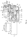
- Fig. 1 is a sectional view of an automatic hydraulic pressure generator utilizing an operation device according to an embodiment of the invention.
- Fig.1 shows an automatic hydraulic pressure generator in a transmission of an automobile where a friction clutch (not shown) is connected or disconnected by computer control.
- the automatic hydraulic pressure generator comprises an operation device 1 in this embodiment, a case 2 enclosing the operation device 1, a hydraulic master cylinder 3 mounted on the front side of the case 2, and a motor 4 mounted on the upper side of the case 2. Also, a reservoir tank 5 is connected and arranged on the upper side of the hydraulic master cylinder 3.
- the motor 4 can be rotated forward and backward and is driven and controlled by a computer (not shown).
- the hydaulic master cylinder 3 has a connection part 3a communicating with the piping for an operating cylinder of a friction clutch (not shown). Structures of the motor 4 and the hydraulic master cylinder 3 themselves are known well, and when a piston rod 6 of the hydraulic master cylinder 3 is moved forward through the operation device 1 by drive of the motor 4, the hydraulic master cylinder 3 generates hydraulic pressure and supplies it to the operating cylinder, and when the piston rod 6 is moved rearward, the hydraulic pressure is released.
- the case 2 is constituted by a front case 2a and a rear case 2b, and the rear case 2b has a cylindrical part 2b1 partially projecting in the front case 2a.
- the piston rod 6 is projected from the front side, and a stationary shaft 7, coaxial and opposite to the piston rod 6, is fixed to the rear case 2b through a fixing screw 8 and is positioned within a cylindrical part 2b1 of the rear case 2b.
- a sleeve 9 is mounted slidably in the axial direction through a slide key 10, and the front end of the sleeve 9 is tightened and fixed to the bulged rear end of the piston rod 6 through a flared nut 11. Also, on the inner circumference of the front side of the cylindrical part 2b1 of the rear case 2b, a bearing 12 slidably engaging with the outer circumference of the sleeve 9 is mounted.
- a bellow-shaped cover 14 is mounted between the front end of the cylindrical part 2b1 and an annular flange 13 formed on the inner wall of the front case 2a opposite to the cylindrical part 2b1, and the coupling part of the sleeve 9 and the piston rod 6 is shielded by the cover 14.
- the front end of a slider 15 is coupled with the rear end part of the sleeve 9 so as to be rotatable relatively to and movable integrally with the sleeve 9 in the axial direction through a slider bearing 16 comprising a ball bearing. That is, the rear end part of the sleeve 9 is fixed to an inner race of the slider bearing 16 and the front end of the slider 15 is fixed to an outer race of the slider bearing 16.
- the slider bearing 16 corresponds to "coupling means" as defined in claim 1.
- the outer circumference of the slider 15 is guided by a bearing 17 mounted on the inner circumference of the cylindrical part 2b1.
- a slider side actuator gear 18 having outer circumferential teeth and a female screw member 19 with a female screw formed on the inner circumference are fixed in overlaid state in the axial direction by screws 20 ⁇ 20 (only one is shown in the figure). Also, at the rear part of the stationary shaft 7 positioned in the inside of the female screw member 19, a male screw member 21 meshing with the female screw member 19 is fixed not to be rotatable through a fixing key 22.
- a counter side actuator gear 23 is positioned on the upper side of the slider side actuator 18, a counter side actuator gear 23 is positioned.
- the counter side actuator 23 is mounted on a counter shaft 24 in parallel to the stationary shaft 7, and the counter shaft 24 is supported at both ends on the rear case 2b through ball bearings 25, 25.
- the counter side actuator 23 comprises a first gear part 23a meshing with the slider side actuator gear 18 and a second gear part 23b of larger diameter with teeth more in number than the first gear part 23a. Length of the first part 23a (length in the axial direction) is formed longer than that of the slider side actuator gear 18 and thereby the slider 15 can be moved in the axial direction as described later.
- the second gear part 23b meshes with a motor side actuator gear 27 mounted on the motor shaft 4a of the motor 4 through a spring 26 and having teeth less in number than the second gear part 23b.
- the motor side actuator gear 27, the counter side actuator gear 23 and the slider side actuator gear 18 constitute actuator gear train which reduces rotation of the motor 4 and transmits the reduced rotation to the slider 15.
- Fig.1 the piston rod 6, the sleeve 9 and the slider 15 are shown in upper half in the position that the piston rod 6 is moved rearward and in the oil hydraulic pressure release state (rearward moving position) and in lower half in the position that the piston rod 6 is moved forward and in the oil hydraulic pressure generating state (forward moving position). Description will be performed based on the initial state that the piston rod 6 is moved rearward and in the oil hydraulic pressure release. condition.
- the motor 4 is rotated in the direction reverse that described above. Then, the slider 15 is moved rearward with respect to the stationary shaft 7 (to the right in the figure), and together with the slider 15, the sleeve 9 and further the piston rod 6 are moved rearward and the oil hydraulic pressure release state is produced.
- the speed reduction of the motor 4 is performed by the actuator gear train, the number of teeth in the gear or the number of the gears themselves is set suitably, and thereby the desired torque can be obtained.
- the piston rod 6 can be operated at high torque and at high speed.
- the female screw member 19 and the male screw member 21 are made multiple thread screws, the moving speed of the piston rod 6 relative to the rotation of the motor 4 can be increased, and in combination with constitution of the trapezoidal thread screw as above described, the increase of the moving speed and the improvement of the durability can be achieved simultaneously.
- each of the motor side actuator gear 27, the counter side actuator gear 23 and the slider side actuator gear 18 as above described may be formed by nylon resin, and material of the female screw member 19 and the male screw member 21 of the stationary shaft 7 may be brass and carbon steel respectively, and material of the slide key 10 may be polyimide resin, and material of bearings 12, 17 slidably contacting with the outer circumference of the sleeve 9 and the outer circumference of the slider 15 may be PTFE resin. It is preferable that the slider bearing 16 coupling the sleeve 9 rotatably relative to the slider 15 and further the ball bearings 25, 25 of the counter shaft 24 are made of a grease infusion type, and thereby the operation device 1 is constituted as a dry type. As a result, there are advantages that maintenance is not required and oil leakage is not produced in the operation device 1.
- the slider 15 and the female screw member 19 are constituted separately and also the stationary shaft 7 and the male screw member 21 are constituted separately, the slider 15 itself may have a female screw and also the stationary shaft 7 itself may have a male screw.
Landscapes
- Engineering & Computer Science (AREA)
- General Engineering & Computer Science (AREA)
- Mechanical Engineering (AREA)
- Physics & Mathematics (AREA)
- Fluid Mechanics (AREA)
- Electromagnetism (AREA)
- Transportation (AREA)
- Transmission Devices (AREA)
- Hydraulic Clutches, Magnetic Clutches, Fluid Clutches, And Fluid Joints (AREA)
- Connection Of Motors, Electrical Generators, Mechanical Devices, And The Like (AREA)
- Actuator (AREA)
Claims (5)
- Betätigungseinrichtung zur Betätigung eines hydraulischen Hauptzylinders (3) mittels Motorantrieb, dadurch gekennzeichnet, daß sie folgendes aufweist:ein Gleitstück (15), welches von einem Motor (4) über einen Antriebsradsatz (27, 23, 18) zum Zweck der Drehzahlreduktion um eine stationäre Welle (7) in Rotation versetzt wird,eine Schraube mit Innengewinde (19), die an einem Innenumfang des genannten Gleitstücks (15) ausgebildet ist,eine Schraube mit Außengewinde (21), die an einem Außenumfang der genannten stationären Welle (7) angeordnet ist und mit der genannten Schraube mit Innengewinde (19) in Eingriff steht,eine Hülse (9), die an einer Kolbenstange (6) des genannten hydraulischen Hauptzylinders (3) befestigt und entlang der genannten stationären Welle (7) in axialer Richtung verschiebbar ist, undKupplungsmittel (16) zur Verbindung der genannten Hülse (9) mit dem genannten Gleitstück (15) in der Weise, daß die genannte Hülse und das genannte Gleitstück im Verhältnis zueinander um die axiale Richtung drehbar und in axialer Richtung miteinander integral beweglich sind.
- Betätigungseinrichtung für einen hydraulischen Hauptzylinder nach Anspruch 1, dadurch gekennzeichnet, daß die Schraube mit Innengewinde (19) des genannten Gleitstücks (15) und die Schraube mit Außengewinde (21) am Außenumfang der genannten stationären Welle (7) jeweils Schrauben mit mehrgängigem Trapezgewinde sind.
- Betätigungseinrichtung für einen hydraulischen Hauptzylinder nach Anspruch 1 oder 2, dadurch gekennzeichnet, daß der Außenumfang des genannten Gleitstücks (15) und der Außenumfang der genannten Hülse (9) in einem Gehäuse (2) der Betätigungseinrichtung mittels Lagern (12, 17) verschiebbar gelagert sind.
- Betätigungseinrichtung für einen hydraulischen Hauptzylinder nach Anspruch 1, 2 oder 3, dadurch gekennzeichnet, daß das genannte Kupplungsmittel (16) zur Verbindung der genannten Hülse (9) mit dem genannten Gleitstück (15) ein Gleitstücklager aufweist.
- Betätigungseinrichtung nach einem der vorstehenden Ansprüche, dadurch gekennzeichnet, daß für jedes Zahnrad des genannten Antriebsradsatz, die genannte Schraube mit Außengewinde und die genannte Schraube mit Innengewinde sowie für das genannte Lager und das genannte Gleitstücklager, soweit vorhanden, Materialien oder Teile verwendet werden, die nicht geölt werden müssen.
Applications Claiming Priority (3)
| Application Number | Priority Date | Filing Date | Title |
|---|---|---|---|
| JP01204997A JP3613623B2 (ja) | 1997-01-06 | 1997-01-06 | 油圧マスタシリンダの作動装置 |
| JP12049/97 | 1997-01-06 | ||
| JP1204997 | 1997-01-06 |
Publications (3)
| Publication Number | Publication Date |
|---|---|
| EP0852297A2 EP0852297A2 (de) | 1998-07-08 |
| EP0852297A3 EP0852297A3 (de) | 1998-11-04 |
| EP0852297B1 true EP0852297B1 (de) | 2001-11-28 |
Family
ID=11794755
Family Applications (1)
| Application Number | Title | Priority Date | Filing Date |
|---|---|---|---|
| EP98300021A Expired - Lifetime EP0852297B1 (de) | 1997-01-06 | 1998-01-05 | Betätigungseinrichtung für einen hydraulischen Hauptzylinder |
Country Status (5)
| Country | Link |
|---|---|
| US (1) | US6047546A (de) |
| EP (1) | EP0852297B1 (de) |
| JP (1) | JP3613623B2 (de) |
| KR (1) | KR100477715B1 (de) |
| DE (1) | DE69802588T2 (de) |
Cited By (2)
| Publication number | Priority date | Publication date | Assignee | Title |
|---|---|---|---|---|
| CN101635485B (zh) * | 2009-08-24 | 2011-09-28 | 浙江大学 | 一种集成式液压驱动的异步发电机 |
| CN111092515A (zh) * | 2019-12-20 | 2020-05-01 | 太原理工大学 | 一种集成式机电-液压驱动与储能一体化作动装置 |
Families Citing this family (19)
| Publication number | Priority date | Publication date | Assignee | Title |
|---|---|---|---|---|
| US6595338B2 (en) * | 2001-09-26 | 2003-07-22 | New Venture Gear, Inc. | Torque transfer clutch with linear piston hydraulic clutch actuator |
| DE10393512B4 (de) * | 2002-11-07 | 2017-03-09 | Schaeffler Technologies AG & Co. KG | Vorrichtung zum Betrieb eines Kraftfahrzeuges, insbesondere zum Betätigen eines automatisierten Getriebes eines Kraftfahrzeuges |
| US7165469B2 (en) * | 2003-04-10 | 2007-01-23 | M-B-W Inc. | Shift rod piston seal arrangement for a vibratory plate compactor |
| US20050189190A1 (en) * | 2004-02-27 | 2005-09-01 | Kowalsky Christopher J. | Electrohydraulic clutch assembly |
| US8297142B2 (en) | 2007-03-22 | 2012-10-30 | Nsk Ltd. | Actuator |
| DE102007018469A1 (de) * | 2007-04-19 | 2008-10-23 | Robert Bosch Gmbh | Elektromechanischer Bremskraftverstärker |
| JP4984061B2 (ja) | 2007-05-31 | 2012-07-25 | 日立オートモティブシステムズ株式会社 | 電動倍力装置 |
| US8235198B2 (en) * | 2008-11-20 | 2012-08-07 | Borgwarner, Inc. | Hydraulic clutch assembly for a motor vehicle driveline |
| FR2947228B1 (fr) * | 2009-06-25 | 2012-11-30 | Bosch Gmbh Robert | Systeme de freins a servofrein electrique |
| CN103209873B (zh) * | 2010-11-17 | 2015-08-26 | 本田技研工业株式会社 | 电动制动执行器的车身安装结构 |
| DE102012218255A1 (de) * | 2011-10-26 | 2013-05-02 | Schaeffler Technologies AG & Co. KG | Verfahren zum Ansteuern einer Kupplung |
| WO2015090316A1 (de) * | 2013-12-17 | 2015-06-25 | Schaeffler Technologies AG & Co. KG | Hydrostatische aktuatoranordnung und verfahren zur montage einer derartigen aktuatoranordnung |
| ITTO20131050A1 (it) * | 2013-12-19 | 2015-06-20 | Freni Brembo Spa | Dispositivo attuatore per freni a controllo automatico |
| US9815445B2 (en) | 2014-10-29 | 2017-11-14 | Bwi (Shanghai) Co., Ltd. | Brake booster assembly |
| US10507817B2 (en) * | 2014-11-04 | 2019-12-17 | Hitachi Automotive Systems, Ltd. | Electric motor-driven booster |
| WO2017046380A1 (de) * | 2015-09-17 | 2017-03-23 | Lucas Automotive Gmbh | Elektromechanischer bremskraftverstärker |
| JP6838935B2 (ja) * | 2016-10-31 | 2021-03-03 | Ntn株式会社 | 電動アクチュエータ |
| FR3069595B1 (fr) * | 2017-07-31 | 2019-08-23 | Valeo Embrayages | Actionneur d'embrayage |
| FR3069597B1 (fr) * | 2017-07-31 | 2019-08-23 | Valeo Embrayages | Actionneur d'embrayage |
Family Cites Families (8)
| Publication number | Priority date | Publication date | Assignee | Title |
|---|---|---|---|---|
| US3956896A (en) * | 1975-04-18 | 1976-05-18 | Bailey Charles A | Method and apparatus for displacing fluid |
| DE2909204C2 (de) * | 1979-03-09 | 1982-08-19 | Wacker-Werke Gmbh & Co Kg, 8077 Reichertshofen | Schwingungserreger mit zwei Unwuchten |
| DE3525981A1 (de) * | 1985-07-20 | 1987-01-29 | Schulz Gerd Fahrzeug Cont | Schwenkvorrichtung fuer ein schleuderkettenaggregat eines kraftfahrzeugs |
| US4653815A (en) * | 1985-10-21 | 1987-03-31 | General Motors Corporation | Actuating mechanism in a vehicle wheel brake and anti-lock brake control system |
| GB8724985D0 (en) * | 1987-10-26 | 1987-12-02 | Automotive Prod Plc | Hydraulic actuator |
| GB9312461D0 (en) * | 1993-06-17 | 1993-08-04 | Aflex Hose Ltd | Improvements in and relating to flexible hose products |
| DE4320205A1 (de) * | 1993-06-18 | 1994-12-22 | Fichtel & Sachs Ag | Stellantrieb für eine Kraftfahrzeug-Reibungskupplung |
| DE4433824C2 (de) | 1994-09-22 | 1996-10-02 | Fichtel & Sachs Ag | Stelleinrichtung mit einem Getriebe |
-
1997
- 1997-01-06 JP JP01204997A patent/JP3613623B2/ja not_active Expired - Fee Related
- 1997-12-12 KR KR1019970068388A patent/KR100477715B1/ko not_active IP Right Cessation
-
1998
- 1998-01-05 EP EP98300021A patent/EP0852297B1/de not_active Expired - Lifetime
- 1998-01-05 DE DE69802588T patent/DE69802588T2/de not_active Expired - Fee Related
- 1998-01-06 US US09/003,148 patent/US6047546A/en not_active Expired - Fee Related
Cited By (2)
| Publication number | Priority date | Publication date | Assignee | Title |
|---|---|---|---|---|
| CN101635485B (zh) * | 2009-08-24 | 2011-09-28 | 浙江大学 | 一种集成式液压驱动的异步发电机 |
| CN111092515A (zh) * | 2019-12-20 | 2020-05-01 | 太原理工大学 | 一种集成式机电-液压驱动与储能一体化作动装置 |
Also Published As
| Publication number | Publication date |
|---|---|
| JPH10201173A (ja) | 1998-07-31 |
| DE69802588T2 (de) | 2002-05-23 |
| EP0852297A3 (de) | 1998-11-04 |
| JP3613623B2 (ja) | 2005-01-26 |
| KR100477715B1 (ko) | 2005-07-07 |
| EP0852297A2 (de) | 1998-07-08 |
| KR19980070158A (ko) | 1998-10-26 |
| DE69802588D1 (de) | 2002-01-10 |
| US6047546A (en) | 2000-04-11 |
Similar Documents
| Publication | Publication Date | Title |
|---|---|---|
| EP0852297B1 (de) | Betätigungseinrichtung für einen hydraulischen Hauptzylinder | |
| US5159847A (en) | Sector plate for transfer case | |
| KR100574612B1 (ko) | 나사 액추에이터 및 그러한 액추에이터를 포함하는브레이크 캘리퍼 | |
| US5735767A (en) | Add-on two-speed compounder | |
| US6491140B2 (en) | Electric disc brake | |
| US20110113913A1 (en) | Gear Shifting Mechanism for the Vehicle Automatic Transmission | |
| KR101293020B1 (ko) | 마모 보상 클러치 액츄에이터 | |
| US6470764B1 (en) | Electric drive device for transmission | |
| US4278156A (en) | Clutch engaging and disengaging means | |
| EP0843112B1 (de) | Gangschaltvorrichtung für ein automatisiertes, mechanisches Schaltgetriebe | |
| EP0898099B1 (de) | Automatisierte Schaltvorrichtung für ein Gangwechselgetriebe | |
| US4225024A (en) | Locking device for reverse gear of a motor vehicle transmission, especially for an automobile | |
| WO2017129610A2 (en) | Clutch actuator for a vehicle | |
| US6000517A (en) | Automatic clutch operating apparatus | |
| KR101306636B1 (ko) | 기준위치의 조정이 용이한 마모보상 클러치 액츄에이터 | |
| US5934433A (en) | Friction clutch having an actuator for automated operation | |
| CA1118693A (en) | Means for coupling a hand drive with a rotatable shaft | |
| JP2002349698A (ja) | 車両用変速機のギア変速装置 | |
| KR19990066816A (ko) | 마찰클러치의 자동단속장치 | |
| US3738229A (en) | Hydraulically operated cylinder-piston unit | |
| US6561331B1 (en) | Transmission unit for a vehicle | |
| CN211371196U (zh) | 离合器传动单元及电控执行模块 | |
| KR20120077500A (ko) | 차량용 클러치 액추에이터 | |
| JP2003227567A (ja) | 変速機用電動駆動装置 | |
| KR100527694B1 (ko) | 자동차용 클러치 유격 조절 구조 |
Legal Events
| Date | Code | Title | Description |
|---|---|---|---|
| PUAI | Public reference made under article 153(3) epc to a published international application that has entered the european phase |
Free format text: ORIGINAL CODE: 0009012 |
|
| AK | Designated contracting states |
Kind code of ref document: A2 Designated state(s): DE FR GB IT SE |
|
| AX | Request for extension of the european patent |
Free format text: AL;LT;LV;MK;RO;SI |
|
| PUAL | Search report despatched |
Free format text: ORIGINAL CODE: 0009013 |
|
| AK | Designated contracting states |
Kind code of ref document: A3 Designated state(s): AT BE CH DE DK ES FI FR GB GR IE IT LI LU MC NL PT SE |
|
| AX | Request for extension of the european patent |
Free format text: AL;LT;LV;MK;RO;SI |
|
| 17P | Request for examination filed |
Effective date: 19990111 |
|
| AKX | Designation fees paid |
Free format text: DE FR GB IT SE |
|
| 17Q | First examination report despatched |
Effective date: 20000807 |
|
| GRAG | Despatch of communication of intention to grant |
Free format text: ORIGINAL CODE: EPIDOS AGRA |
|
| GRAG | Despatch of communication of intention to grant |
Free format text: ORIGINAL CODE: EPIDOS AGRA |
|
| GRAH | Despatch of communication of intention to grant a patent |
Free format text: ORIGINAL CODE: EPIDOS IGRA |
|
| GRAH | Despatch of communication of intention to grant a patent |
Free format text: ORIGINAL CODE: EPIDOS IGRA |
|
| GRAA | (expected) grant |
Free format text: ORIGINAL CODE: 0009210 |
|
| AK | Designated contracting states |
Kind code of ref document: B1 Designated state(s): DE FR GB IT SE |
|
| REG | Reference to a national code |
Ref country code: GB Ref legal event code: IF02 |
|
| REF | Corresponds to: |
Ref document number: 69802588 Country of ref document: DE Date of ref document: 20020110 |
|
| PLBE | No opposition filed within time limit |
Free format text: ORIGINAL CODE: 0009261 |
|
| STAA | Information on the status of an ep patent application or granted ep patent |
Free format text: STATUS: NO OPPOSITION FILED WITHIN TIME LIMIT |
|
| 26N | No opposition filed | ||
| PGFP | Annual fee paid to national office [announced via postgrant information from national office to epo] |
Ref country code: IT Payment date: 20060131 Year of fee payment: 9 |
|
| PGFP | Annual fee paid to national office [announced via postgrant information from national office to epo] |
Ref country code: DE Payment date: 20061229 Year of fee payment: 10 |
|
| PGFP | Annual fee paid to national office [announced via postgrant information from national office to epo] |
Ref country code: GB Payment date: 20070103 Year of fee payment: 10 |
|
| PGFP | Annual fee paid to national office [announced via postgrant information from national office to epo] |
Ref country code: SE Payment date: 20070104 Year of fee payment: 10 |
|
| PGFP | Annual fee paid to national office [announced via postgrant information from national office to epo] |
Ref country code: FR Payment date: 20070109 Year of fee payment: 10 |
|
| EUG | Se: european patent has lapsed | ||
| GBPC | Gb: european patent ceased through non-payment of renewal fee |
Effective date: 20080105 |
|
| PG25 | Lapsed in a contracting state [announced via postgrant information from national office to epo] |
Ref country code: DE Free format text: LAPSE BECAUSE OF NON-PAYMENT OF DUE FEES Effective date: 20080801 |
|
| REG | Reference to a national code |
Ref country code: FR Ref legal event code: ST Effective date: 20081029 |
|
| PG25 | Lapsed in a contracting state [announced via postgrant information from national office to epo] |
Ref country code: GB Free format text: LAPSE BECAUSE OF NON-PAYMENT OF DUE FEES Effective date: 20080105 |
|
| PG25 | Lapsed in a contracting state [announced via postgrant information from national office to epo] |
Ref country code: SE Free format text: LAPSE BECAUSE OF NON-PAYMENT OF DUE FEES Effective date: 20080106 |
|
| PG25 | Lapsed in a contracting state [announced via postgrant information from national office to epo] |
Ref country code: FR Free format text: LAPSE BECAUSE OF NON-PAYMENT OF DUE FEES Effective date: 20080131 |
|
| PG25 | Lapsed in a contracting state [announced via postgrant information from national office to epo] |
Ref country code: IT Free format text: LAPSE BECAUSE OF NON-PAYMENT OF DUE FEES Effective date: 20070105 |