EP0851167A2 - Vorrichtung zum Erkennen des Verbindungszustandes eines Luftrohres - Google Patents
Vorrichtung zum Erkennen des Verbindungszustandes eines Luftrohres Download PDFInfo
- Publication number
- EP0851167A2 EP0851167A2 EP97403112A EP97403112A EP0851167A2 EP 0851167 A2 EP0851167 A2 EP 0851167A2 EP 97403112 A EP97403112 A EP 97403112A EP 97403112 A EP97403112 A EP 97403112A EP 0851167 A2 EP0851167 A2 EP 0851167A2
- Authority
- EP
- European Patent Office
- Prior art keywords
- air
- air tube
- valve
- actuated valve
- gas
- Prior art date
- Legal status (The legal status is an assumption and is not a legal conclusion. Google has not performed a legal analysis and makes no representation as to the accuracy of the status listed.)
- Withdrawn
Links
Images


Classifications
-
- F—MECHANICAL ENGINEERING; LIGHTING; HEATING; WEAPONS; BLASTING
- F17—STORING OR DISTRIBUTING GASES OR LIQUIDS
- F17C—VESSELS FOR CONTAINING OR STORING COMPRESSED, LIQUEFIED OR SOLIDIFIED GASES; FIXED-CAPACITY GAS-HOLDERS; FILLING VESSELS WITH, OR DISCHARGING FROM VESSELS, COMPRESSED, LIQUEFIED, OR SOLIDIFIED GASES
- F17C13/00—Details of vessels or of the filling or discharging of vessels
- F17C13/02—Special adaptations of indicating, measuring, or monitoring equipment
-
- F—MECHANICAL ENGINEERING; LIGHTING; HEATING; WEAPONS; BLASTING
- F17—STORING OR DISTRIBUTING GASES OR LIQUIDS
- F17C—VESSELS FOR CONTAINING OR STORING COMPRESSED, LIQUEFIED OR SOLIDIFIED GASES; FIXED-CAPACITY GAS-HOLDERS; FILLING VESSELS WITH, OR DISCHARGING FROM VESSELS, COMPRESSED, LIQUEFIED, OR SOLIDIFIED GASES
- F17C13/00—Details of vessels or of the filling or discharging of vessels
- F17C13/04—Arrangement or mounting of valves
-
- F—MECHANICAL ENGINEERING; LIGHTING; HEATING; WEAPONS; BLASTING
- F17—STORING OR DISTRIBUTING GASES OR LIQUIDS
- F17C—VESSELS FOR CONTAINING OR STORING COMPRESSED, LIQUEFIED OR SOLIDIFIED GASES; FIXED-CAPACITY GAS-HOLDERS; FILLING VESSELS WITH, OR DISCHARGING FROM VESSELS, COMPRESSED, LIQUEFIED, OR SOLIDIFIED GASES
- F17C2205/00—Vessel construction, in particular mounting arrangements, attachments or identifications means
- F17C2205/03—Fluid connections, filters, valves, closure means or other attachments
- F17C2205/0302—Fittings, valves, filters, or components in connection with the gas storage device
- F17C2205/0323—Valves
- F17C2205/0326—Valves electrically actuated
-
- F—MECHANICAL ENGINEERING; LIGHTING; HEATING; WEAPONS; BLASTING
- F17—STORING OR DISTRIBUTING GASES OR LIQUIDS
- F17C—VESSELS FOR CONTAINING OR STORING COMPRESSED, LIQUEFIED OR SOLIDIFIED GASES; FIXED-CAPACITY GAS-HOLDERS; FILLING VESSELS WITH, OR DISCHARGING FROM VESSELS, COMPRESSED, LIQUEFIED, OR SOLIDIFIED GASES
- F17C2221/00—Handled fluid, in particular type of fluid
- F17C2221/03—Mixtures
- F17C2221/031—Air
-
- F—MECHANICAL ENGINEERING; LIGHTING; HEATING; WEAPONS; BLASTING
- F17—STORING OR DISTRIBUTING GASES OR LIQUIDS
- F17C—VESSELS FOR CONTAINING OR STORING COMPRESSED, LIQUEFIED OR SOLIDIFIED GASES; FIXED-CAPACITY GAS-HOLDERS; FILLING VESSELS WITH, OR DISCHARGING FROM VESSELS, COMPRESSED, LIQUEFIED, OR SOLIDIFIED GASES
- F17C2227/00—Transfer of fluids, i.e. method or means for transferring the fluid; Heat exchange with the fluid
- F17C2227/03—Heat exchange with the fluid
- F17C2227/0302—Heat exchange with the fluid by heating
-
- F—MECHANICAL ENGINEERING; LIGHTING; HEATING; WEAPONS; BLASTING
- F17—STORING OR DISTRIBUTING GASES OR LIQUIDS
- F17C—VESSELS FOR CONTAINING OR STORING COMPRESSED, LIQUEFIED OR SOLIDIFIED GASES; FIXED-CAPACITY GAS-HOLDERS; FILLING VESSELS WITH, OR DISCHARGING FROM VESSELS, COMPRESSED, LIQUEFIED, OR SOLIDIFIED GASES
- F17C2227/00—Transfer of fluids, i.e. method or means for transferring the fluid; Heat exchange with the fluid
- F17C2227/04—Methods for emptying or filling
- F17C2227/044—Methods for emptying or filling by purging
-
- F—MECHANICAL ENGINEERING; LIGHTING; HEATING; WEAPONS; BLASTING
- F17—STORING OR DISTRIBUTING GASES OR LIQUIDS
- F17C—VESSELS FOR CONTAINING OR STORING COMPRESSED, LIQUEFIED OR SOLIDIFIED GASES; FIXED-CAPACITY GAS-HOLDERS; FILLING VESSELS WITH, OR DISCHARGING FROM VESSELS, COMPRESSED, LIQUEFIED, OR SOLIDIFIED GASES
- F17C2250/00—Accessories; Control means; Indicating, measuring or monitoring of parameters
- F17C2250/03—Control means
- F17C2250/032—Control means using computers
-
- F—MECHANICAL ENGINEERING; LIGHTING; HEATING; WEAPONS; BLASTING
- F17—STORING OR DISTRIBUTING GASES OR LIQUIDS
- F17C—VESSELS FOR CONTAINING OR STORING COMPRESSED, LIQUEFIED OR SOLIDIFIED GASES; FIXED-CAPACITY GAS-HOLDERS; FILLING VESSELS WITH, OR DISCHARGING FROM VESSELS, COMPRESSED, LIQUEFIED, OR SOLIDIFIED GASES
- F17C2250/00—Accessories; Control means; Indicating, measuring or monitoring of parameters
- F17C2250/04—Indicating or measuring of parameters as input values
- F17C2250/0404—Parameters indicated or measured
- F17C2250/043—Pressure
-
- F—MECHANICAL ENGINEERING; LIGHTING; HEATING; WEAPONS; BLASTING
- F17—STORING OR DISTRIBUTING GASES OR LIQUIDS
- F17C—VESSELS FOR CONTAINING OR STORING COMPRESSED, LIQUEFIED OR SOLIDIFIED GASES; FIXED-CAPACITY GAS-HOLDERS; FILLING VESSELS WITH, OR DISCHARGING FROM VESSELS, COMPRESSED, LIQUEFIED, OR SOLIDIFIED GASES
- F17C2250/00—Accessories; Control means; Indicating, measuring or monitoring of parameters
- F17C2250/04—Indicating or measuring of parameters as input values
- F17C2250/0404—Parameters indicated or measured
- F17C2250/0443—Flow or movement of content
-
- F—MECHANICAL ENGINEERING; LIGHTING; HEATING; WEAPONS; BLASTING
- F17—STORING OR DISTRIBUTING GASES OR LIQUIDS
- F17C—VESSELS FOR CONTAINING OR STORING COMPRESSED, LIQUEFIED OR SOLIDIFIED GASES; FIXED-CAPACITY GAS-HOLDERS; FILLING VESSELS WITH, OR DISCHARGING FROM VESSELS, COMPRESSED, LIQUEFIED, OR SOLIDIFIED GASES
- F17C2250/00—Accessories; Control means; Indicating, measuring or monitoring of parameters
- F17C2250/04—Indicating or measuring of parameters as input values
- F17C2250/0404—Parameters indicated or measured
- F17C2250/0478—Position or presence
-
- F—MECHANICAL ENGINEERING; LIGHTING; HEATING; WEAPONS; BLASTING
- F17—STORING OR DISTRIBUTING GASES OR LIQUIDS
- F17C—VESSELS FOR CONTAINING OR STORING COMPRESSED, LIQUEFIED OR SOLIDIFIED GASES; FIXED-CAPACITY GAS-HOLDERS; FILLING VESSELS WITH, OR DISCHARGING FROM VESSELS, COMPRESSED, LIQUEFIED, OR SOLIDIFIED GASES
- F17C2250/00—Accessories; Control means; Indicating, measuring or monitoring of parameters
- F17C2250/06—Controlling or regulating of parameters as output values
- F17C2250/0605—Parameters
- F17C2250/0636—Flow or movement of content
-
- F—MECHANICAL ENGINEERING; LIGHTING; HEATING; WEAPONS; BLASTING
- F17—STORING OR DISTRIBUTING GASES OR LIQUIDS
- F17C—VESSELS FOR CONTAINING OR STORING COMPRESSED, LIQUEFIED OR SOLIDIFIED GASES; FIXED-CAPACITY GAS-HOLDERS; FILLING VESSELS WITH, OR DISCHARGING FROM VESSELS, COMPRESSED, LIQUEFIED, OR SOLIDIFIED GASES
- F17C2270/00—Applications
- F17C2270/05—Applications for industrial use
- F17C2270/0518—Semiconductors
-
- Y—GENERAL TAGGING OF NEW TECHNOLOGICAL DEVELOPMENTS; GENERAL TAGGING OF CROSS-SECTIONAL TECHNOLOGIES SPANNING OVER SEVERAL SECTIONS OF THE IPC; TECHNICAL SUBJECTS COVERED BY FORMER USPC CROSS-REFERENCE ART COLLECTIONS [XRACs] AND DIGESTS
- Y10—TECHNICAL SUBJECTS COVERED BY FORMER USPC
- Y10T—TECHNICAL SUBJECTS COVERED BY FORMER US CLASSIFICATION
- Y10T137/00—Fluid handling
- Y10T137/8158—With indicator, register, recorder, alarm or inspection means
- Y10T137/8359—Inspection means
Definitions
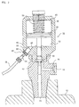
- Fig. 1 is a rough view showing one embodiment of the present invention.
- the branch pipe 80 has a flow restriction (a fixed throttle valve) 84 provided therein.
- a pressure switch 86 is connected to the branch pipe 80 between the socket 82 and the flow restriction 84. The pressure switch 86 will be switched off when the internal pressure of the branch pipe 80 in the same portion is reduced less than a predetermined value. It is set, in the illustrated embodiment, so as to be turned on in reduction of pressure.
- the microcomputer 88 When an operator turns on an input device of the control panel 90 (for example an exchanging work start-up switch 92) in order to start up the gas container-exchanging work, the microcomputer 88 first releases the excitation of the solenoid 74 of the direction control valve 72 in the air supply system 54 on the basis of its input signal, thereby stopping the supply of compressed air so that the air-actuated valve 16 is closed. Then, it closes the shut-off valve 24 in the pipe 14 (the steps 100 & 102).
- an input device of the control panel 90 for example an exchanging work start-up switch 92
- the microcomputer 88 causes a display unit 94 on the control panel 90 to display a guidance of transferring the plug 64 of the air tube 56 into the socket 82 at a refuge position (the step 104).
- the operator draws out the plug 64 from the socket 62 of the valve 16 and sets it in the socket 82 at the refuge position.
- the passage of the socket 82 is opened so that the branch pipe 80 and the air tube 56 are in communication with each other. Accordingly, the compressed air flows through the branch pipe 80, air tube 56 and direction control valve 72 in turn from the supply source 70, and then it is discharged to the atmosphere. At that time, the flow restriction 84 reduces the flow rate of the compressed air flowing here. Further, since the passage of the socket 82 is changed from a closed state to an opened state, the internal pressure of the branch pipe 80 is decreased so that the pressure switch 86 is switched over to produce an on signal into the microcomputer 88.
- the microcomputer 88 recognizes that the air tube 56 is connected to the socket 82 at the refuge position. If the operator turns on a purge start-up switch 96 of the control panel 90 in such a situation, the shut-off valves 32, 34 in the pipes 28, 30 are opened. Accordingly, purge gas is caused to flow through the pipe 28 from the purge gas supply source so that the special material gas existing in the pipe 14 between the valve 16 and the shut-off valve 24 is released from the vent pipe 30 to the atmosphere (the steps 106, 108 & 110).
- the microcomputer 88 releases the lock of a gas container-exchanging door of the cylinder cabinet (the step 116). Accordingly, it becomes possible to exchange the gas container 12 (the step 118).
- this gas-tightness check step will be automatically started up after the gas-tightness check start-up switch 98 is turned on.
- the same switch is turned on, it is detected again depending on a signal from the pressure switch 86 whether the plug 64 of the air tube 56 is connected to the socket 82 at the refuge position, and if it is judged that the same plug 64 is connected, it will lock the door of the cylinder cabinet and to start up the gas-tightness check step (the steps 122, 124 & 126).
- the plug 64 may be connected with the valve 16. Hence, the gas-tightness check step will not be carried out and the operation will return to step 122, and await the connection of plug 64 to the socket 82 at the refuge position (the step 128).
- the microcomputer 88 causes the display unit 94 to display a guidance of connecting the air tube 56 to an air-actuated valve 16 of a new gas container 12 (the step 130). On the basis of this display, the operator draws out the plug 64 of the air tube 56 from the socket 82 at the refuge position and inserts it for connection into the socket 62 of the valve 16.
- the plug 64 is detached from the socket 82 at the refuge position, the passage of the socket 82 is closed by means of a valve mechanism in the socket 82 so that the stream of air passing through the branch pipe 80 is stopped.
- the internal pressure switch 86 is switched over so that an off signal is sent to the microcomputer 88.
- the microcomputer 88 regards, on the basis of the off signal from the pressure switch 86, that the plug 64 is connected to the socket 62 of the valve 16 (the step 132). Then, the operator turns on the purge start-up switch 96 again, and hence the shut-off valves 32, 34 in the pipes 28, 30 are opened (the steps 134 & 136).
- the purge gas is permitted to flow in, and the inside of the pipe opened to the atmosphere is cleaned up.
- an on signal is not produced from the pressure switch 86, it is judged that the air tube 56 is not connected to the valve 16, and even if the switch 96 is pushed down, the purge is not started up (the steps 138 & 140).
- the microcomputer 88 closes the shut-off valves 32, 34 and opens the shut-up valve 24 (the step 142). If compressed air is thereafter supplied to the valve 16 through the air tube 56, the special material gas may be supplied to the semiconductor-manufacturing unit from the gas container 12.
- the gas container-exchanging work has been described above, the aforementioned process is merely one example and it may be variously modified. For instance, a result of recognizing the connection state of the air tube 56 may be displayed in the display unit 94. In a case where it is made a proviso that the air tube 56 is detached, also in works other than the gas container-exchanging work, it is a matter of course that the apparatus according to the present invention can be used for checking said proviso.
- the gas supply system is not limited to one for supplying a special material gas into a semiconductor-manufacturing unit.
- a means of detecting that the fore end of the air tube 56 is in the refuge position there can be conceived various means.
- air is supplied through the branch pipe 80 from the compressed air supply source 70 in the aforementioned embodiment, it may be possible to separately provide another exclusive air supply source as the air supply means and to connect the air tube thereto.
- a means of detecting the flowing of air there may be used a pressure sensor, a flow rate sensor or the like, not limited to the pressure switch.
- a photoelectric sensor As to a means of detecting the connection of an air tube, it may be conceived to use a photoelectric sensor.
- a transparent type of photoelectric sensor may be provided on the inner wall surface of the socket 82.
- the connection state of the air tube may be detected depending on a change in the detection signal produced when the plug 64 is connected to the socket, running cross the photoelectric sensor.
- a socket is attached at the fore end of the air tube 56, as mentioned above, a to-be-connected member of the same shape as a plug to be connected to the socket may be provided at the refuge position.
- the light-projecting part and light-receiving part of a reflex type photoelectric sensor may be formed on the fore end of this to-be-connected member. This utilizes the fact that a metallic plate in contact with the fore end of a plug exists in the inside of the socket and said plant can reflex light.
- the detecting apparatus according to the present invention is used in a case where an air tube is detached from the air-actuated valve of a gas container so as to close the same valve, as mentioned above, the connection state of the air tube and the valve can be detected. If system maintenance work is carried out on the basis of the detection result in a system using a special material gas such as a silane series gas, accordingly, maintenance work when air tube is connected with the valve can be prevented and hence the safety is remarkably improved.
- a special material gas such as a silane series gas
Landscapes
- Engineering & Computer Science (AREA)
- Mechanical Engineering (AREA)
- General Engineering & Computer Science (AREA)
- Filling Or Discharging Of Gas Storage Vessels (AREA)
- Fluid-Pressure Circuits (AREA)
- Lining Or Joining Of Plastics Or The Like (AREA)
Applications Claiming Priority (2)
| Application Number | Priority Date | Filing Date | Title |
|---|---|---|---|
| JP350697/96 | 1996-12-27 | ||
| JP35069796A JP3892922B2 (ja) | 1996-12-27 | 1996-12-27 | エア供給システム |
Publications (2)
| Publication Number | Publication Date |
|---|---|
| EP0851167A2 true EP0851167A2 (de) | 1998-07-01 |
| EP0851167A3 EP0851167A3 (de) | 1998-10-21 |
Family
ID=18412238
Family Applications (1)
| Application Number | Title | Priority Date | Filing Date |
|---|---|---|---|
| EP97403112A Withdrawn EP0851167A3 (de) | 1996-12-27 | 1997-12-22 | Vorrichtung zum Erkennen des Verbindungszustandes eines Luftrohres |
Country Status (3)
| Country | Link |
|---|---|
| US (1) | US5899225A (de) |
| EP (1) | EP0851167A3 (de) |
| JP (1) | JP3892922B2 (de) |
Families Citing this family (7)
| Publication number | Priority date | Publication date | Assignee | Title |
|---|---|---|---|---|
| JP4070281B2 (ja) * | 1997-12-25 | 2008-04-02 | 日本エア・リキード株式会社 | シリンダキャビネット |
| DE19824940A1 (de) * | 1998-06-04 | 1999-12-09 | Mannesmann Sachs Ag | Betätigungseinrichtung für Kraftfahrzeuge mit integrierter Positionserkennung |
| US7001784B2 (en) * | 2003-09-19 | 2006-02-21 | Taiwan Semiconductor Manufacturing Co. Ltd. | Method to control spacer width |
| JP2007136031A (ja) * | 2005-11-22 | 2007-06-07 | Senko Medical Instr Mfg Co Ltd | 抜管検知装置 |
| US10307718B2 (en) * | 2017-01-17 | 2019-06-04 | Sodastream Industries Ltd. | Pneumatically operated valve for carbonation machine |
| EP3674594B1 (de) | 2018-12-28 | 2023-04-05 | Chart Inc. | Speichertank mit druckbetätigter füllabschlussanordnung |
| US12272465B2 (en) * | 2019-05-14 | 2025-04-08 | Michael Rhodes | Quick connect valve testing and tune-up setup for valves at a nuclear power plant |
Family Cites Families (6)
| Publication number | Priority date | Publication date | Assignee | Title |
|---|---|---|---|---|
| US2435343A (en) * | 1944-05-18 | 1948-02-03 | Lewis W Downey | Power shutoff and signalling apparatus |
| DE1017433B (de) * | 1957-04-20 | 1957-10-10 | Babcock & Wilcox Dampfkessel | UEberdrucksicherung fuer Schiebergehaeuse |
| US3431031A (en) * | 1965-01-28 | 1969-03-04 | Wiz Corp | Vehicle brake operator |
| US4872482A (en) * | 1988-06-24 | 1989-10-10 | Air Products And Chemicals, Inc. | Remotely controlled operator for gas cylinder valve |
| US5145331A (en) * | 1991-07-29 | 1992-09-08 | J. Wagner Gmbh | Diaphragm pump |
| FR2692964B1 (fr) * | 1992-06-25 | 1994-10-07 | Butagaz | Appareil de contrôle automatique de la présence ou de l'absence d'un joint dans le nez de robinet d'une bouteille de gaz. |
-
1996
- 1996-12-27 JP JP35069796A patent/JP3892922B2/ja not_active Expired - Fee Related
-
1997
- 1997-12-22 EP EP97403112A patent/EP0851167A3/de not_active Withdrawn
- 1997-12-24 US US08/998,228 patent/US5899225A/en not_active Expired - Fee Related
Also Published As
| Publication number | Publication date |
|---|---|
| JPH10185098A (ja) | 1998-07-14 |
| US5899225A (en) | 1999-05-04 |
| JP3892922B2 (ja) | 2007-03-14 |
| EP0851167A3 (de) | 1998-10-21 |
Similar Documents
| Publication | Publication Date | Title |
|---|---|---|
| US6189369B1 (en) | Gas leakage detecting apparatus | |
| EP0688983B1 (de) | Ventilanordnung für einen Druckgasbehälter | |
| EP0991539B1 (de) | Kraftstoffdämpfesteuerungssystem für kraftfahrzeuge | |
| US6691729B2 (en) | Valve assembly | |
| EP0893293B1 (de) | Leitungssystem zur Zuführung von gasförmigem Brennstoff | |
| JPS6326470A (ja) | ガスタンクのための弁 | |
| US20110162717A1 (en) | Apparatus and method for testing an aircraft tank system | |
| US5899225A (en) | Air tube connection state detecting apparatus | |
| US5709436A (en) | Arrangement for connecting a test device to a railroad car brake control valve device | |
| US6327898B1 (en) | Fuel system leakage detector | |
| US4341245A (en) | Gas inlet attachment for a gas charger | |
| CN102080615A (zh) | 燃料箱 | |
| US5350222A (en) | Auxiliary stabilizer valve for VX vent valve | |
| JP2023543634A (ja) | 極低温燃料補給装置を動作させる方法 | |
| US5207482A (en) | Vent valve device having disabling means | |
| US5714684A (en) | Test plat adapter for manual single car tester | |
| CN212537255U (zh) | 气动工业电视的气路保护装置 | |
| CN210322223U (zh) | 一种电空阀检测装置 | |
| CN110514368B (zh) | 一种电空阀检测装置 | |
| JPH0678699U (ja) | ガス供給装置 | |
| JP4923191B2 (ja) | 燃料電池システムに用いる水素ガス容器用バルブ装置 | |
| JP2944957B2 (ja) | リリーフ弁およびそれを備えるガス供給装置 | |
| JP4543354B2 (ja) | エンジンのガス燃料供給装置 | |
| KR200210925Y1 (ko) | 가스관용 퍼지(Purge)장치 | |
| EP1256433B1 (de) | Entlastungsventil für GID-Formwerkzeug und Regelungsverfahren |
Legal Events
| Date | Code | Title | Description |
|---|---|---|---|
| PUAI | Public reference made under article 153(3) epc to a published international application that has entered the european phase |
Free format text: ORIGINAL CODE: 0009012 |
|
| AK | Designated contracting states |
Kind code of ref document: A2 Designated state(s): BE CH DE ES FR GB IT LI NL |
|
| AX | Request for extension of the european patent |
Free format text: AL;LT;LV;MK;RO;SI |
|
| PUAL | Search report despatched |
Free format text: ORIGINAL CODE: 0009013 |
|
| AK | Designated contracting states |
Kind code of ref document: A3 Designated state(s): AT BE CH DE DK ES FI FR GB GR IE IT LI LU MC NL PT SE |
|
| AX | Request for extension of the european patent |
Free format text: AL;LT;LV;MK;RO;SI |
|
| RAP1 | Party data changed (applicant data changed or rights of an application transferred) |
Owner name: AIR LIQUIDE JAPAN, LTD. |
|
| 17P | Request for examination filed |
Effective date: 19990421 |
|
| AKX | Designation fees paid |
Free format text: BE CH DE ES FR GB IT LI NL |
|
| STAA | Information on the status of an ep patent application or granted ep patent |
Free format text: STATUS: THE APPLICATION HAS BEEN WITHDRAWN |
|
| 18W | Application withdrawn |
Effective date: 20030320 |