EP0849867B1 - Schrittmotor sowie Verwendung - Google Patents
Schrittmotor sowie Verwendung Download PDFInfo
- Publication number
- EP0849867B1 EP0849867B1 EP97119186A EP97119186A EP0849867B1 EP 0849867 B1 EP0849867 B1 EP 0849867B1 EP 97119186 A EP97119186 A EP 97119186A EP 97119186 A EP97119186 A EP 97119186A EP 0849867 B1 EP0849867 B1 EP 0849867B1
- Authority
- EP
- European Patent Office
- Prior art keywords
- rotor
- stator
- width
- angle
- motor according
- Prior art date
- Legal status (The legal status is an assumption and is not a legal conclusion. Google has not performed a legal analysis and makes no representation as to the accuracy of the status listed.)
- Expired - Lifetime
Links
- 238000004804 winding Methods 0.000 claims description 16
- 230000005284 excitation Effects 0.000 claims description 6
- 239000004020 conductor Substances 0.000 claims 1
- 238000000034 method Methods 0.000 description 2
- 241000555745 Sciuridae Species 0.000 description 1
- 230000001419 dependent effect Effects 0.000 description 1
- 238000003780 insertion Methods 0.000 description 1
- 230000037431 insertion Effects 0.000 description 1
- 230000013011 mating Effects 0.000 description 1
- 235000012771 pancakes Nutrition 0.000 description 1
- 230000007704 transition Effects 0.000 description 1
Images




Classifications
-
- H—ELECTRICITY
- H02—GENERATION; CONVERSION OR DISTRIBUTION OF ELECTRIC POWER
- H02K—DYNAMO-ELECTRIC MACHINES
- H02K37/00—Motors with rotor rotating step by step and without interrupter or commutator driven by the rotor, e.g. stepping motors
- H02K37/02—Motors with rotor rotating step by step and without interrupter or commutator driven by the rotor, e.g. stepping motors of variable reluctance type
- H02K37/08—Motors with rotor rotating step by step and without interrupter or commutator driven by the rotor, e.g. stepping motors of variable reluctance type with rotors axially facing the stators
-
- H—ELECTRICITY
- H02—GENERATION; CONVERSION OR DISTRIBUTION OF ELECTRIC POWER
- H02K—DYNAMO-ELECTRIC MACHINES
- H02K37/00—Motors with rotor rotating step by step and without interrupter or commutator driven by the rotor, e.g. stepping motors
- H02K37/02—Motors with rotor rotating step by step and without interrupter or commutator driven by the rotor, e.g. stepping motors of variable reluctance type
- H02K37/06—Motors with rotor rotating step by step and without interrupter or commutator driven by the rotor, e.g. stepping motors of variable reluctance type with rotors situated around the stators
Definitions
- the invention relates to a stepper motor with at least one Exciter winding, a stator with on its outer circumference distributed poles and a rotor, which has a plurality of rotor segments which together with the stator poles at Excitation each close a magnetic circuit.
- JP-A-58083576 discloses such a stepping motor.
- Stepper motors consist in particular of a soft magnetic cup-shaped stator, which includes a field winding. On the circumference of the pot stator poles are arranged. Stator and rotor are coaxial with respect to their central axis mounted to each other, so that an air gap between the rotor and stator arises. From DE 42 41 966 C1 is a Stepper motor with a disk system known.
- the stepper motor according to claim 1 allows the rotor during the energization of the excitation winding far beyond the Middle between his starting position and the next detent position rotates.
- Previous solutions in particular with Einspulenantrieb, reach exactly one middle position during the energization between starting position and next detent position. To be sure of this particular unstable center position to come to the next detent position, require previous Solutions a repulsive magnet pair, which is just before the Middle position is arranged.
- the stepper motor according to the invention moves the rotor so close to the next detent position Come on, that a snap in this position after switching off the current is safe for excitation winding.
- the switching time is shortened because still closed during the energization of the next RF path becomes.
- an undefined middle position occurred in which the HF switch without continuity was with total reflection.
- An old one Switch had the switching time as the switching time plus settling time.
- the stepper motor according to the invention leaves one as possible rectangular torque curve over the angle of rotation. It is also possible an angle-dependent moment course ever to achieve after application.
- the invention may be for different Motor designs are used, for. For example Disc rotor, squirrel cage etc.
- Crucial for the function is a stator pole width which is less than half Angular segment width and a varying rotor segment width, wherein a rotor segment has approximately the stator pole width.
- the task is performed by a stepper motor solved with the features of claim 1.
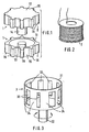
- FIG. 1 shows, there is an embodiment of the Stepping motor according to the invention of a stator 1, the two coaxial intermeshing cup-shaped hollow bodies 11 and 12 is formed.
- the first hollow body 11 has a cylindrical center pin 13 which of a centric hollow pin 14 of the other hollow body 12 at Mating the two hollow body is umsch.
- the Hollow pin 14 serves to receive the field winding 2, the is designed as a cylindrical Einspulenand extract ( Figure 2).
- stator 11 and 12 On the outer circumference of the stator 11 and 12 is a plurality of n equidistant stator poles 15 distributed by intervening Air gaps 16 are separated from each other.
- the Polau touch lake are rectangular in shape, wherein the longer rectangle sides parallel to the central axis of the Stators 1 run. The transitions to the air gaps 16 are rounded, so that a Polground of the poles each wider is the pole end.
- the rotor 3 for this embodiment is shown in FIG. 3 shown. It consists of a cylinder shell 31 with at least a lid surface to which the rotor axis 32 is attached is. Rotor 3 and stator are relative to a common Supported center axis, so that between the stator poles 15th and the rotor segments 34, an air gap is formed. Because the rotor rotatably mounted, the system has an endeavor to the smallest magnetic resistance or after the maximum value to aspire to the magnetic energy. So on the rotor is a moment measurable. In the cylinder shell of the rotor 3 are rectangular vertical slots or openings 33 arranged, so that in between webs, so-called rotor segments 34, arise.
- the angular width of the individual rotor segments 34 is different and varies between the angular width a stator pole 15 and the angular segment width, here 45 °, minus the angular width of a stator pole.
- at Excitation close the stator poles together with the rotor segments a magnetic circuit.
- the angular width of the stator poles 15 by at least one Factor greater than 2 smaller than the angle segment width.
- Factor greater than 2 smaller than the angle segment width.
- the stator poles 8 ° and the rotor segments vary here preferably continuously increasing in a range between 8 ° and 33 °.
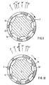
- the movement process is shown in Figures 6 to 12 and that for the Size of an angular segment of 45 °.
- FIG. 6 shows the zero position of the rotor. The arrow therefore points to 0 °.
- FIG. 7 shows the Position after the first phase of rotation. The arrow points to 7 °.
- the position is at 10 ° ( Figure 8), after the third phase of rotation at 14 ° ( Figure 9), after the fourth phase of rotation at 22 ° ( Figure 10), after the fifth rotational phase at 28 ° ( Figure 11) and after the sixth Rotational phase at 32 ° ( Figure 12).
- FIG. 12 stopping takes place as long as the current supply continues.
- the Trailing edge of the next Statorpoles then aligned with the Leading edge of the first rotor segment.
- the movement of the rotor is of course continuous.
- FIGS. 6 to 12 show only instant pictures.
- the drive rotor thus leads when energizing the excitation winding with DC a step of 32 ° and stays in this attitude.
- the step size about 80% up to the next detent position.
- the step size 72 ° At an angle segment of 90 ° is the step size 72 °, at an angle segment of 45 ° is the step size 36 ° and at an angle segment of 360 °, d. H. at a full circle, 288 °.
- the structure of the stepper motor can be maintained while maintaining the previously principle of action also be different.
- the embodiment according to Figure 4 shows the longitudinal section through a Disk rotor stepping motor.
- the stator 1 consists of a cup-shaped hollow body with a center pin 17 to Recording the exciter winding 2. At the center pin 17 is in its end area in diameter expands to the magnetic circuit better to close. At the edge of the pot has the hollow body Incisions 18 which separate the stator poles 15 from each other. The angular width of the stator poles and the angular width the corresponding cuts can be made according to the previous one presented embodiment can be selected.
- the rotor 3 is here designed as a rotor disc with an outer diameter, preferably the outer diameter of the Stators 1 corresponds.
- the rotor 3 On the outer circumference, the rotor 3 has radial extending slots 35, which are preferably the same are deeply formed as the wall thickness of the Statortopfes. Between these slots 35 remain rotor segments, the as in the previously presented embodiment in their Angle width vary, for example between 8 ° and 33 °.
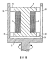
- FIG. 1 Another embodiment of the stepping motor according to the invention is shown in FIG.
- the stator 1 integrally formed. It consists of a circular cylinder, in at least one of its end portions 19 in diameter is enlarged. Here are both end areas by cylindrical discs enlarged, so that the stator has a shape similar to one Has thread roll.
- the cylindrical discs are toothed on the outside, such that as in the previously illustrated embodiment the stator poles 15 arise.
- the rotor 3 is like in the embodiment of Figure 1 as a the stator. 1 enclosing external rotor formed. In its outer surface are also 15 slots in the area of the stator poles or breakthroughs 33 are provided, the rotor segments 34th separate each other.
- the exciter winding 2 is located preferably in the area between the cylindrical disks symmetrically to the central axis of the stator. 1
- FIG. 14 shows the torque curve M over the step width.
- the wide catch range in the range of the angle widths of 35 ° up to 45 ° is due to the inventive dimensioning of Rotor poles and stator segments reached.
Landscapes
- Engineering & Computer Science (AREA)
- Power Engineering (AREA)
- Control Of Stepping Motors (AREA)
- Iron Core Of Rotating Electric Machines (AREA)
Description
- Figur 1
- einen aus zwei Teilen zusammensetzbaren Stator,
- Figur 2
- eine Erregerspule zum Einbringen in den Rotor,
- Figur 3
- einen Außenläuferrotor,
- Figur 4
- einen Längsschnitt durch einen Scheibenläufer-Schrittmotor,
- Figur 5
- einen Querschnitt durch den Rotor letzteren Schrittmotors,
- Figur 6-12
- unterschiedliche Stellungen des Rotors in Bezug auf den Stator,
- Figur 13
- einen Schrittmotor mit anders gestaltetem Stator und
- Figur 14
- einen Momentenverlauf.
Claims (11)
- Schrittmotor bestehend ausmindestens einer Erregerwicklung (2),einem Stator (1), der auf seinem Außenumfang verteilt eine Mehrzahl von Polen (15) mit dazwischenliegenden Luftspalten (16) aufweist, wobei die Winkelbreiten der Statorpole (15) untereinander gleich und jeweils kleiner sind als eine halbe Winkelsegmentbreite, wobei sich die Winkelsegmentbreite als Teilung von 360° durch eine ganze Zahl n ergibt,einem Rotor (3) mit einer Mehrzahl von Rotorsegmenten (34), die zusammen mit den Statorpolen (15) bei Erregung jeweils einen Magnetkreis schließen, wobei die Winkelbreite der einzelnen Rotorsegmente (34) unterschiedlich ist und variiert zwischen der Winkelbreite eines Statorpoles (15) und der Winkelsegmentbreite abzüglich der Winkelbreite eines Statorpoles (15).
- Schrittmotor nach Anspruch 1, dadurch gekennzeichnet, daß der Stator (1) aus zwei topfförmigen Hohlkörpern (11, 12) mit auf ihrem Außenumfang angeordneten Statorpolen (15) besteht, daß einer dieser Hohlkörper (11) einen Mittelzapfen (13) aufweist, der von einem zentralen Hohlzapfen (14) des anderen Hohlkörpers (12) umschließbar ist, wobei letzterer insbesondere als Tragkörper für die Erregerwicklung (2) dient, und daß der Rotor (3) als Außenläufer den Stator (1) umschließt, wobei in seiner Mantelfläche Schlitze oder Durchbrüche (33) angeordnet sind, die die Rotorsegmente (34) voneinander trennen.
- Schrittmotor nach Anspruch 1, dadurch gekennzeichnet, daß der Stator (1) aus einem insbesondere die Erregerwicklung (2) tragenden Zylinder besteht, der mindestens in einem seiner Endbereiche (19) im Durchmesser vergrößert ist, daß im Bereich dieser Durchmesservergrößerung/en die Statorpole (15) ausgebildet sind und daß der Rotor (3) als Außenläufer den Stator (1) umschließt, wobei in seiner Mantelfläche Schlitze oder Durchbrüche (35) angeordnet sind, die die Rotorsegmente (34) voneinander trennen.
- Schrittmotor nach Anspruch 1, dadurch gekennzeichnet, daß der Stator (1) aus einem topfförmigen Hohlkörper besteht mit einem Mittelzapfen (17), insbesondere zur Aufnahme der Erregerwicklung (2), wobei der Hohlkörper an seinem Topfrand Einschnitte (18) aufweist, die die Statorpole (15) voneinander trennen, daß der Rotor (3) als Scheibenläufer ausgebildet ist, der insbesondere an seinem Außenumfang Schlitze (35) aufweist, die die Rotorsegmente (34) voneinander trennen.
- Schrittmotor nach einem der Ansprüche 1 bis 4, dadurch gekennzeichnet, daß die Variation der Winkelbreite der einzelnen Rotorsegmente (34) dadurch realisiert ist, daß bei gleichbreiten Schlitzen oder Durchbrüchen (33, 35) im Bereich der Statorpole (15) Einschnürungen variierender Breite vorgesehen sind.
- Schrittmotor nach einem der Ansprüche 1 bis 5, dadurch gekennzeichnet, daß die Erregerwicklung (2) als Einspulenwicklung symmetrisch zur Mittelachse des Stators (1) angeordnet ist.
- Schrittmotor nach einem der Ansprüche 1 bis 6, dadurch gekennzeichnet, daß die Rotorsegmente (34) bezüglich der Statorpole (15) auf dem Umfang so verteilt sind, daß die Endlage des Rotors (3) nach einer Bestromung der Erregerwicklung (2) in der Nähe der nächsten Raststellung des Schrittmotors ist.
- Schrittmotor nach einem der Ansprüche 1 bis 7, dadurch gekennzeichnet, daß die Winkelbreite der Statorpole (15) um mindestens einen Faktor größer 2 kleiner ist als die Winkelsegmentbreite.
- Schrittmotor nach Anspruch 8, dadurch gekennzeichnet, daß die bei einer Winkelsegmentbreite von 45° die Winkelbreite der Statorpole (15) etwa 8° ist und die Winkelbreite der Rotorsegmente (34) zwischen etwa 8° und 33° variiert.
- Schrittmotor nach einem der Ansprüche 1 bis 9, dadurch gekennzeichnet, daß eine Hilfseinrichtung vorgesehen ist, mittels derer der Rotor (3) nach einer Bestromung der Erregerwicklung (2) in seine Ausgangslage oder hin zur nächsten Ausgangslage im nächstfolgenden Winkelsegment einstellbar ist.
- Verwendung des Schrittmotors nach einem der Ansprüche 1 bis 10 für einen Hochfrequenzschalter, insbesondere einen Hohlleiterschalter mit Einspulenantrieb.
Applications Claiming Priority (2)
| Application Number | Priority Date | Filing Date | Title |
|---|---|---|---|
| DE19653833 | 1996-12-21 | ||
| DE19653833A DE19653833A1 (de) | 1996-12-21 | 1996-12-21 | Schrittmotor sowie Verwendung |
Publications (2)
| Publication Number | Publication Date |
|---|---|
| EP0849867A1 EP0849867A1 (de) | 1998-06-24 |
| EP0849867B1 true EP0849867B1 (de) | 2003-02-12 |
Family
ID=7815890
Family Applications (1)
| Application Number | Title | Priority Date | Filing Date |
|---|---|---|---|
| EP97119186A Expired - Lifetime EP0849867B1 (de) | 1996-12-21 | 1997-11-03 | Schrittmotor sowie Verwendung |
Country Status (2)
| Country | Link |
|---|---|
| EP (1) | EP0849867B1 (de) |
| DE (2) | DE19653833A1 (de) |
Families Citing this family (2)
| Publication number | Priority date | Publication date | Assignee | Title |
|---|---|---|---|---|
| CN106356592B (zh) * | 2016-11-29 | 2018-10-12 | 中国电子科技集团公司第四十一研究所 | 一种高隔离单刀双掷机械波导开关 |
| CN112582764B (zh) * | 2020-10-29 | 2021-08-31 | 中国航天时代电子有限公司 | 一种新型微波开关 |
Family Cites Families (5)
| Publication number | Priority date | Publication date | Assignee | Title |
|---|---|---|---|---|
| GB1199155A (en) * | 1966-10-31 | 1970-07-15 | Plessey Co Ltd | Improvements in or relating to Rotary Electric Machines |
| DE1817369A1 (de) * | 1968-12-28 | 1970-07-09 | Wolfram Crede | Elektromagnetischer Schrittgeber,insbesondere Antrieb fuer Kleinwerke |
| JPS5883576A (ja) * | 1981-11-09 | 1983-05-19 | Copal Co Ltd | ステツピングモ−タ |
| JP2518639B2 (ja) * | 1987-03-11 | 1996-07-24 | 日本サ−ボ株式会社 | ステツピングモ−タ |
| DE4241966C1 (de) * | 1992-12-12 | 1994-03-03 | Teldix Gmbh | Schrittmotor |
-
1996
- 1996-12-21 DE DE19653833A patent/DE19653833A1/de not_active Withdrawn
-
1997
- 1997-11-03 EP EP97119186A patent/EP0849867B1/de not_active Expired - Lifetime
- 1997-11-03 DE DE59709307T patent/DE59709307D1/de not_active Expired - Fee Related
Also Published As
| Publication number | Publication date |
|---|---|
| EP0849867A1 (de) | 1998-06-24 |
| DE19653833A1 (de) | 1998-06-25 |
| DE59709307D1 (de) | 2003-03-20 |
Similar Documents
| Publication | Publication Date | Title |
|---|---|---|
| DE69513655T2 (de) | Mehrfachgeschwindigkeitsmotor | |
| EP0286905B1 (de) | Elektronisch kommutierter, kollektorloser Gleichstrommotor | |
| DE3632509C2 (de) | ||
| EP1173917B1 (de) | Stromerzeugereinheit aus generator und hubkolbenverbrennungsmotor als antrieb | |
| DE68914235T2 (de) | Synchronmotor, dessen Drehrichtung gewählt werden kann. | |
| DE68912964T2 (de) | Elektromagnetische Stellantriebe. | |
| DE69707829T2 (de) | Kompakter Schrittmotor | |
| DE2225442B2 (de) | Kollektorloser Gleichstrommotor | |
| DE1918500A1 (de) | Impulsbetaetigter elektrischer Stellantrieb | |
| EP0614263B1 (de) | Einphasiger Reluktanzmotor und Anordnung zum Starten dieses Motors in einer gewünschten Drehrichtung | |
| DE2702190B2 (de) | Steueranordnung fur einen bürstenlosen Motor | |
| DE69921211T2 (de) | Elektrische Maschine mit doppelter Erregung, und insbesondere Fahrzeuggenerator | |
| DE2841838A1 (de) | Zylindrische laeuferwicklung fuer kernlose elektrische maschinen | |
| DE2331120A1 (de) | Schrittmotor | |
| EP0849867A1 (de) | Schrittmotor sowie Verwendung | |
| DE10055080C2 (de) | Elektrische Linearmaschine | |
| DE2913691C2 (de) | Ständer für einen bürstenlosen Elektromotor | |
| DE2332012C2 (de) | ||
| DE2834579C2 (de) | Motor | |
| DE2560207C3 (de) | Kollektorloser Gleichstrommotor | |
| DE2706691C3 (de) | Motor | |
| DE3609835A1 (de) | Einphasenmotor | |
| DE2828640A1 (de) | Elektromotor | |
| DE3502284A1 (de) | Kollektorloser gleichstrommotor | |
| EP1102386A2 (de) | Gleichstrommaschine |
Legal Events
| Date | Code | Title | Description |
|---|---|---|---|
| PUAI | Public reference made under article 153(3) epc to a published international application that has entered the european phase |
Free format text: ORIGINAL CODE: 0009012 |
|
| AK | Designated contracting states |
Kind code of ref document: A1 Designated state(s): DE FR GB IT |
|
| AX | Request for extension of the european patent |
Free format text: AL;LT;LV;MK;RO;SI |
|
| 17P | Request for examination filed |
Effective date: 19981228 |
|
| AKX | Designation fees paid |
Free format text: DE FR GB IT |
|
| RBV | Designated contracting states (corrected) |
Designated state(s): DE FR GB IT |
|
| 17Q | First examination report despatched |
Effective date: 20010502 |
|
| GRAH | Despatch of communication of intention to grant a patent |
Free format text: ORIGINAL CODE: EPIDOS IGRA |
|
| RAP1 | Party data changed (applicant data changed or rights of an application transferred) |
Owner name: TESAT-SPACECOM GMBH & CO. KG |
|
| GRAH | Despatch of communication of intention to grant a patent |
Free format text: ORIGINAL CODE: EPIDOS IGRA |
|
| GRAA | (expected) grant |
Free format text: ORIGINAL CODE: 0009210 |
|
| AK | Designated contracting states |
Designated state(s): DE FR GB IT |
|
| REG | Reference to a national code |
Ref country code: GB Ref legal event code: FG4D Free format text: NOT ENGLISH |
|
| REF | Corresponds to: |
Ref document number: 59709307 Country of ref document: DE Date of ref document: 20030320 Kind code of ref document: P |
|
| GBT | Gb: translation of ep patent filed (gb section 77(6)(a)/1977) | ||
| ET | Fr: translation filed | ||
| PLBE | No opposition filed within time limit |
Free format text: ORIGINAL CODE: 0009261 |
|
| STAA | Information on the status of an ep patent application or granted ep patent |
Free format text: STATUS: NO OPPOSITION FILED WITHIN TIME LIMIT |
|
| 26N | No opposition filed |
Effective date: 20031113 |
|
| PG25 | Lapsed in a contracting state [announced via postgrant information from national office to epo] |
Ref country code: DE Free format text: LAPSE BECAUSE OF NON-PAYMENT OF DUE FEES Effective date: 20040602 |
|
| PG25 | Lapsed in a contracting state [announced via postgrant information from national office to epo] |
Ref country code: IT Free format text: LAPSE BECAUSE OF NON-PAYMENT OF DUE FEES Effective date: 20051103 |
|
| REG | Reference to a national code |
Ref country code: FR Ref legal event code: PLFP Year of fee payment: 19 |
|
| REG | Reference to a national code |
Ref country code: FR Ref legal event code: PLFP Year of fee payment: 20 |
|
| PGFP | Annual fee paid to national office [announced via postgrant information from national office to epo] |
Ref country code: FR Payment date: 20161118 Year of fee payment: 20 Ref country code: GB Payment date: 20161122 Year of fee payment: 20 |
|
| REG | Reference to a national code |
Ref country code: GB Ref legal event code: PE20 Expiry date: 20171102 |
|
| PG25 | Lapsed in a contracting state [announced via postgrant information from national office to epo] |
Ref country code: GB Free format text: LAPSE BECAUSE OF EXPIRATION OF PROTECTION Effective date: 20171102 |