EP0849698B1 - Image processing method and apparatus - Google Patents
Image processing method and apparatus Download PDFInfo
- Publication number
- EP0849698B1 EP0849698B1 EP97122194A EP97122194A EP0849698B1 EP 0849698 B1 EP0849698 B1 EP 0849698B1 EP 97122194 A EP97122194 A EP 97122194A EP 97122194 A EP97122194 A EP 97122194A EP 0849698 B1 EP0849698 B1 EP 0849698B1
- Authority
- EP
- European Patent Office
- Prior art keywords
- stroke
- information
- input
- stroke information
- clustering
- Prior art date
- Legal status (The legal status is an assumption and is not a legal conclusion. Google has not performed a legal analysis and makes no representation as to the accuracy of the status listed.)
- Expired - Lifetime
Links
Images

Classifications
-
- G—PHYSICS
- G06—COMPUTING OR CALCULATING; COUNTING
- G06V—IMAGE OR VIDEO RECOGNITION OR UNDERSTANDING
- G06V30/00—Character recognition; Recognising digital ink; Document-oriented image-based pattern recognition
- G06V30/10—Character recognition
- G06V30/32—Digital ink
- G06V30/333—Preprocessing; Feature extraction
Definitions
- the present invention relates to an image processing method and apparatus for processing handwritten image information written by an operator.
- the present invention relates to an image processing method and apparatus for handling stroke data formed of a plurality of coordinate information.
- handwriting information input apparatuses which input handwriting information and edit it, for example, input traces drawn by an operator as strokes by using a handwriting input member, such as a pen or a mouse, and edit the input strokes.
- Such a handwriting information input apparatus is set in such a way that a trace drawn continuously is input as one stroke, and this one stroke is handled as a minimum unit. Since the apparatus is set so that one stroke is handled as a minimum unit as described above, when the same editing is performed on a plurality of input strokes, a method of grouping a plurality of input strokes into one data is often used so that a plurality of strokes are edited collectively by taking into consideration editing efficiency.
- a method of grouping a plurality of input strokes into one data there is a method in which each object stroke is selected and indicated individually from among the strokes input by the operator, and a plurality of strokes which are indicated so as to be grouped is handled as one data.
- EP-A-0 539 749 discloses an automatic recognition of handwritten text based on a suitable representation of the handwriting in one or several feature vector space(s), Euclidean and Gaussian modeling in each space and mixture decoding to take into account the contribution of all relevant prototypes in all spaces.
- the underlying models are trained using training data formed by stroke information acquired via a stylus or pen. During the training a vector of feature elements is generated. These features elements comprise an inter-stroke distance if a training character is composed of more than one stroke.
- EP-A-0 562 767 discloses a method of recognizing handwritten symbols which involves inputting strokes of a symbol via a pen touching a pad.
- a processor takes samples of the position of the tip of the pen at a sampling rate and stores these samples in a memory.
- a determination is made as to whether the input symbol is complete. This is effected by checking an interval between a time at which the pen if lifted off the pad and a time at which the pen touches the pad again. If this interval is shorter than a predetermined threshold then it is decided that an additional stroke belonging to the input symbol follows. Otherwise it is assumed that the input symbol is complete.
- each object stroke must be selected and indicated from among the input strokes, and this indication operation requires a lot of time and effort.
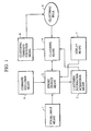
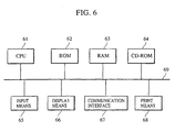
- Fig. 1 is a block diagram illustrating the functional construction of a handwriting information input apparatus according to the present invention, which is realized by the apparatus shown in the block diagram of Fig. 6.
- a CPU 61 performs all the processes concerned with the present invention in accordance with control programs stored in a ROM 62, a RAM 63, or a CD-ROM 64.
- a clustering information acquisition means 3, a clustering means 4, a clustering command execution means 6, and a command execution means 8 are controlled by the CPU 61.
- the ROM 62 has stored therein control programs and parameters used for various processing, by which the CPU 61 performs processes concerned with the present invention such as the process shown in the flowchart, which will be described later.
- the RAM 63 also stores control programs and parameters concerned with the present invention, and is provided with a working area for storing data that are generated in the middle of processing.
- Buffers BufA and BufB are provided within the RAM 63, and stroke data and clustering data are also stored in the RAM 63.
- a stroke storage means 2, in Fig. 1, is realized by the RAM 63, and a clustering rule 5 is previously stored in the ROM 62.
- the CD-ROM 64 which can be removed from the main unit of this apparatus, is a storage medium in which control programs for processes concerned with the present invention, which are performed by the CPU 61, and parameters that are required for processes are prestored. The control programs and data stored in the CD-ROM 64 may be used after they are stored temporarily in the RAM 63.
- An input means 65 includes a pointing device and a tablet capable of pointing or selecting a desired position on the display means 66 and a keyboard capable of inputting characters, symbols, functions, modes, and so on.
- the input means 65 allows inputting of strokes, and an pointing operation of icons, for example, an indication operation of a clustering execute icon or an indication operation of a cluster display icon, which will be described later.
- the stroke input means 1 in Fig. 1 is realized by the input means 65.
- the display means 66 formed of a CRT or an LCD, displays characters, images, icons, and the like.
- a display screen such as that shown in Fig. 3, is generated on this display means 66.
- the display means 7 in Fig. 1 is realized by the display means 66.
- a communication interface 67 controls the communication process for exchange of data with other terminals via a public switched network, a LAN or the like.
- the control programs of processes concerned with the present invention which are stored in the RAM 63, may be those read from the memory of other terminals via the communication interface 67. Further, stroke data and process instruction commands may be input via the communication interface 67, and the processed results may be output via the communication interface 67.
- the print means 68 prints mid-processing and processed results, and is realized by an LBP or an ink jet printer.
- a bus 69 interconnects each means and allows data transmission.
- the handwriting information input apparatus comprises a stroke input means 1 provided with a digitizer on the input surface.
- the stroke input means 1 inputs traces drawn on the input surface by the operator using a pen as stroke data, and further after the stroke data is input, it inputs information about the pen operation progression and operation results.
- This input stroke data includes coordinate sequence data that is generated in unit time from when the pen contacts the input surface until the pen is moved away from the input surface.
- the stroke data represented by the coordinate sequence data obtained during this period is handled as one unit of one stroke.
- Information about the pen operation progression and operation results includes the stroke input time indicating the stroke input start time and end time, and display attributes indicating the pen thickness, and the like.
- the stroke data input from the stroke input means 1 is related with information about the pen operation progression and operation results and stored in the stroke storage means 2 as stroke information. Further, as will be described later, clustered stroke data such that stroke data belonging to the same group is grouped is stored as stroke information in the stroke storage means 2.
- the stroke information of the clustered stroke data and the stroke information of the stroke data are described in different formats so that they may be identified. These formats will be described later with reference to Fig. 2.
- a clustering process is performed by the clustering means 4. Specifically, the clustering means 4 performs a first clustering process each time a new stroke is input from the stroke input means 1.
- the clustering means 4 performs a first clustering process each time a new stroke is input from the stroke input means 1.
- the possibility of clustering between the new input stroke data and the stroke information (stroke data or clustered stroke data) prestored in the stroke storage means 2 is determined in accordance with the clustering information and a clustering rule 5.
- the stroke information which is determined to be capable of being clustered is read from the stroke storage means 2.
- This read stroke information is grouped with the new input stroke data and converted into clustered stroke information and stored in the stroke storage means 2. That is, the read stroke information is rewritten into the stroke information after being converted.
- a second clustering process is performed.
- possibility of clustering between the new input stroke data and the stroke information (stroke data or clustered stroke data) prestored in the stroke storage means 2 is determined in accordance with the clustering information and the clustering rule 5.
- a plurality of stroke information which is determined as being clustered, is read from the stroke storage means 2.
- This read stroke information is grouped with the new input stroke data and converted into single clustered stroke information, and stored in the stroke storage means 2. That is, the read stroke information is rewritten into the stroke information after being converted.
- the clustering information used in the above-described two clustering processes is data required for clustering, and the data are selectively retrieved from the stroke information stored in the stroke storage means 2 by the clustering information acquisition means 3.
- the stroke information the stroke input start time (FT), the stroke input end time (ET), the stroke start point coordinate (FP), the stroke end point coordinate (EP), and positional information are prepared, and stored in a format such as that shown in Fig. 2.
- Required information is extracted from the stroke information according to the type of clustering rule. This positional information indicates the position defined by the center coordinate of a circumscribed rectangle that surrounds a single stroke indicated by the stroke information.
- the clustering rule 5 is a rule for determining whether or not a plurality of stroke information belong to the same group. Specifically, this is a rule for determining whether or not a plurality of stroke information belong to the same group according to the difference in input time between strokes or the difference in position between strokes.
- the first clustering rule 5 used in the first clustering process which is performed each time a new stroke is input from the stroke input means 1, when the difference in input time between strokes (between the new input stroke data and the stroke information stored in the stroke storage means 2) is equal to or less than a predetermined value (e.g., 0.5 sec), or when the difference (distance) between the stroke start point or end point of one stroke and the stroke start point or end point of the other stroke is equal to or less than a predetermined value (e.g., 2 mm), it is defined that each stroke belongs to the same group.
- a predetermined value e.g., 0.5 sec
- a predetermined value e.g. 2 mm
- the second clustering rule 5 used in the second clustering process which is performed when the execution of a clustering process is instructed from the clustering command execution means 6, when the difference (distance) in positional information between the strokes (between the stroke information stored in the stroke storage means 2), namely, the difference between the circumscribed rectangles of each stroke, is equal to or less than a predetermined value (e.g., 3 mm), it is defined that each stroke belongs to the same group.
- a predetermined value e.g., 3 mm
- the reference of clustering of strokes, which are input after the predetermined value is changed, may be changed in accordance with the changing of the predetermined value, or clustering (the same process as the second clustering process) in accordance with a new predetermined value may be performed on all strokes that were input before the changing of the predetermined value.
- the contents of the second clustering rule 5 used for the second clustering process are different from those of the first clustering rule 5 used for the first clustering process. Also, the second clustering process differs from the first clustering process in that clustering between all of the stroke information stored in the stroke storage means 2 is targeted.
- the clustering command execution means 6, as described above, is a means for instructing the clustering means 4 to execute the second clustering process.
- the clustering command execution means 6 When an instruction operation is performed using a clustering execution icon displayed on the screen of the display means 7, the clustering command execution means 6 generates a command for instructing the clustering means 4 to execute the second clustering process so that the second clustering process described earlier is performed.
- the strokes input from the stroke input means 1 are displayed on the display means 7 together with the processing state (clustering state) by the clustering means 4.
- the display means 7 displays the strokes input from the stroke input means 1 on the basis of the stroke information stored in the stroke storage means 2 and displays the cluster state according to the instruction operation of the cluster display icon. Further, the display means 7 displays various icons, including the above-described clustering execution icon and the cluster display icon. In addition to the clustering execution icon and the cluster display icon, these various icons include icons used in the editing operation of the stroke information stored in the stroke storage means 2. Examples of icons are the icons, "Move”, “Delete”, “Grouping", and “Grouping Release". Examples of screen displays by this display means 7 will be described later.
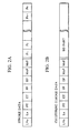
- Fig. 2 shows the format of stroke information stored in the stroke storage means of the handwriting information input apparatus of Fig. 1.
- stroke information of stroke data and the stroke information of clustered stroke data are described in different formats so that they can be identified.
- the stroke information of stroke data is data for one stroke from pen-down to the next pen-up and is described by a sequence of data LV 0 , Ln, FT, ET, FP, EP, M x P, M n P, P 1 , P 2 , ⁇ , and P n , as shown in Fig. 2A.
- LV 0 indicates the clustering level, with data "0" being assigned to LV 0 indicating that clustering has not been performed.
- Ln indicates the data length of this stroke information, and in practice, the number of words (1 word is equal to 16 bits) of the entire stroke data is written therein.
- FT indicates the stroke data input start time.
- ET indicates the stroke data input end time.
- FP indicates the stroke data start-point coordinate.
- EP indicates the stroke data end-point coordinate.
- M x P indicates the maximum coordinates (X,Y) of the stroke data.
- M n P indicates the minimum coordinates (X,Y) of the stroke data. That is, M x P and M n P indicate the diagonal points of a circumscribed rectangle of a stroke.
- P 1 , P 2 , ⁇ , and P n indicate a sequence of points of the coordinates which form the stroke.
- the above-described coordinates coincide with the coordinates on the screen of the display means 7 and represented by the X-Y coordinate system with the upper left corner of the screen as the origin.
- the stroke information of the clustered stroke data is described in a sequence of data LV n , Ln, FT, ET, FP, EP, M x P, M n P, and a BD part, as shown in Fig. 28.
- LV n indicates the clustering level, also indicating the number of times that clustering has been performed.
- Ln indicates the data length of this stroke information similarly to Ln of the stroke information of the stroke data.
- the earliest input start time from among all the stroke input start times contained in this clustered stroke data is assigned to FT.
- the latest input end time from among all the stroke input end times contained in this clustered stroke data is assigned to ET.
- the start-point coordinate of the stroke having the earliest input start time is assigned to FP.
- the end-point coordinate of the stroke having the latest input end time is assigned to EP.
- M x P indicates the maximum coordinates (X,Y) of all the strokes contained in this clustered stroke data.
- M n P indicates the minimum coordinates (X,Y) of the stroke data contained in this clustered stroke data.
- Inserted into the BD part is clustered stroke data having a clustering level lower than the clustering level indicated by LV n . This makes it possible to realize a hierarchical clustered stroke data structure.
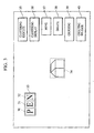
- FIG. 3 shows an example of a hierarchical clustered stroke data structure displayed on the display means of the handwriting information input apparatus of Fig. 1.
- a first clustering process is performed on each stroke.
- the first clustering process since the difference in input time between the strokes which form the character "P" is below the predetermined time, it is determined that the two strokes which form the character "P" belong to the same group, and clustered stroke data such that each stroke which forms the character "P" is grouped is stored as stroke information in the stroke storage means 2.
- This clustered stroke data is formed of data in the format shown in Fig. 2B described above, and the LV n is set to "1".
- each character of the "P", "E” and “N” When the strokes which form each character of these "P", "E” and “N” are being input, as shown in Fig. 3, the strokes which form each character of the "P", “E” and “N” are displayed each in cluster units on the display screen of the display means 7. Specifically, each character, namely, the cluster unit, is displayed together with rectangles (shown by the dotted lines) 30, 31 and 32 which surround it, and the rectangles 30, 31 and 32 shown by these dotted lines make it possible to know the range in which clustering has been performed.
- the first clustering process is performed even if the difference in input time between the strokes is not below the predetermined time.
- the first clustering process also based on the fact that the difference (distance) between the start point and the end point between the strokes is below the predetermined value, it is determined that these strokes belong to the same group, and clustered stroke data such that each stroke which forms this object is grouped is stored as stroke information in the stroke storage means 2.
- the object namely, the cluster unit is displayed surrounded by the rectangle (shown by the dotted line) 34.
- This rectangle is a rectangle expressed by M x P and M n P which are stored in the stroke storage means 2.
- a clustering execution icon 35 a clustering display icon 36, a move icon 37, a delete icon 38, a grouping icon 39, and a grouping release icon 40 are displayed on the display screen of the display means 7.
- the clustering execution icon 35 is an icon for instructing the execution of the above-described second clustering process.
- the second clustering process is performed on all of the stroke information stored in the stroke storage means 2.
- the difference in positional information between each clustered stroke data of the characters "P", "E” and "N” and the stroke data namely, the difference between each clustered stroke and the circumscribed rectangle (the rectangles 30, 31 and 32 in Fig.
- this stroke information indicates a hierarchical data structure including each clustered stroke of "P", "E” and “N” and the stroke, and a rectangle 33 shown by the solid line which surrounds "P", "E” and “N” is displayed as the clustering execution results on the display means 7.
- the clustering display icon 36 is an icon for changing the display format of the clustered stroke data. Each time this icon is pointed, the display format of the clustered stroke data is changed. Specifically, in a state in which the clustered stroke data is displayed surrounded by a rectangle as described above, when the clustering display icon 36 is pointed, the displayed rectangle is deleted, and only the clustered stroke data is displayed.
- the move icon 37, the delete icon 38, the grouping icon 39, and the grouping release icon 40 are icons used for editing operations as described above.
- the pointing of this icon sets the move mode, making possible an editing operation for performing a movement in cluster units.
- the delete icon 38 is an icon for performing deletion in cluster units.
- the grouping icon 39 is an icon for performing grouping in the same way as in a conventional drawing-type application. As a result of the pointing of this icon, a grouping mode is set. In this grouping mode, clustered stroke data or stroke data, which forms cluster units is selected by the operator. When the grouping icon 39 is pointed after this selection is completed, the selected clustered stroke data or stroke data is grouped as one cluster.
- the grouping release icon 40 is an icon for separating the cluster which is grouped in accordance with an instruction from the grouping icon 39 to the original data. By specifying the grouped cluster after this icon is pointed, the BD part of the data having the highest-order clustering level from among the data indicating the cluster is made to remain and the other parts are deleted.
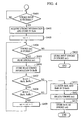
- Fig. 4 is a flowchart illustrating the procedure of the first clustering process in the handwriting information input apparatus of Fig. 1.
- step S401 When stroke input using a pen from the stroke input means 1 is started, as shown in Fig. 4, in the initial step S401, whether or not stroke input is finished is monitored. When it is determined that the stroke input is finished, the process proceeds to step S402 where clustering information is acquired on the basis of the input stroke and stored in a buffer BufA. Clustering information to be stored in the buffer BufA is each of the data from LV 0 to EP shown in Fig. 2A.
- a stroke information counter sct is initialized to "1". This stroke information counter sct makes it possible to sequentially access the stroke information stored in the stroke storage means 2.
- step S404 a check is made to determine whether or not stroke information corresponding to the count value sct of the stroke information counter sct has been stored in the stroke storage means 2.
- step S410 the stroke information indicating the input stroke is stored at a position corresponding to the count value sct of the stroke storage means 2.
- the stroke information stored herein is data of the format shown in Fig. 2A. After the stroke information indicating this input stroke is stored, this process is terminated.
- step S405 stroke information (stroke information (sct)) corresponding to this count value sct is read from the stroke storage means 2.
- this stroke information which has been read is stored in the buffer BufB.
- step S407 the possibility of grouping the input stroke and the read stroke information is determined by comparing the information which becomes the clustering information for the buffer BufA with the clustering information for the buffer BufB in accordance with rule 1, which is a time comparison rule, of the first clustering rule 5 used in the first clustering process.
- rule 1 is a time comparison rule, of the first clustering rule 5 used in the first clustering process.
- the difference between FT of the buffer BufA and ET of the buffer BufB is computed, thus determining whether or not the condition in which this difference, that is, the difference in input times, is equal to or less than the input time difference 0.5 seconds defined by the rule 1 is satisfied.
- the condition of the input time difference defined by this rule 1 it is determined that the input stroke and the read stroke information can be grouped, that is, clustering is possible.
- the condition of the input time difference is not satisfied, it is determined that clustering is not possible.
- step S408 the possibility of grouping the input stroke and the read stroke information is determined by comparing the information which becomes the clustering information for the buffer BufA with the clustering information for the buffer BufB in accordance with rule 2, which is a position comparison rule, of the first clustering rule 5 used in the first clustering process.
- the difference between FP of the buffer BufB and FP of the buffer BufA or the difference between EP of the buffer BufB and EP of the buffer BufA is computed, and a check is made to determine whether or not the condition in which this difference, that is, the difference in input positions, is equal to or less than the input position difference 2 mm defined by the rule 2 is satisfied.
- the condition of the input time difference defined by this rule 2 it is determined that the input stroke and the read stroke information can be grouped, that is, clustering is possible.
- the condition of the input position difference is not satisfied, it is determined that clustering is not possible.
- step S409 the count value sct of the stroke information counter sct is incremented by 1, and the process from step S404 is repeated.
- step S407 When it is determined in step S407 that clustering based on the condition of the input time difference defined by rule 1 is possible, or when it is determined that clustering based on the condition of the input position difference defined by rule 2 is possible, the process proceeds to step S411 where clustering of the input stroke and the read stroke information is performed.
- a process corresponding to the value of the clustering level LV n of the stroke information read from the stroke storage means 2 is performed.
- the value of the LV n of the read stroke information is 1 or more
- information of the buffer BufA is written into the BD part of the read stroke information and the read stroke information is updated.
- this BufA following M n P, a BD part is added in which the read stroke information and the input stroke information are written.
- the information stored in this BufA becomes information such that the input stroke and the read stroke information are grouped.
- step S412 the read stroke information, namely, the stroke information (sct) is deleted from the stroke storage means 2, and in the subsequent step S413, the information of the buffer BufA is stored as stroke information at the storage position of this read stroke information. After this stroke information is stored, this process is terminated.
- the possibility of clustering this input stroke and the previously input stroke is determined in accordance with clustering rule 5 each time a stroke is input from the stroke input means 1.
- stroke information is generated such that this input stroke and the previously input stroke are grouped; therefore it is possible to group a plurality of input strokes efficiently without spending much time and effort on an operation.
- two rules are each applied individually as clustering rule 5 used in the first clustering process performed when a stroke is input. It is not necessary, however, to limit to these rules, and further, it is also possible to increase the number of rules to be applied and to determine the possibility of the execution of clustering so as to perform clustering.
- conditions of the rules to be applied are not limited to the above-described conditions and may be conditions obtained from the stroke information. Needless to say, it is possible to set various conditions.
- a second clustering rule 5 is applied such that when the difference (distance) in position information between strokes (between stroke information stored in the stroke storage means 2), that is, the difference of the distance between the circumscribed rectangles of each stroke, is equal to or less than a predetermined value (e.g., 3 mm), each stroke belongs to the same group.
- the second clustering process is different from the first clustering process in that clustering between all the stroke information stored in the stroke storage means 2 is the object.
- this process initially, waiting for an input of pointing of the clustering execution icon 35 is done.
- the second clustering process is invoked.
- the object stroke information is read from the stroke storage means 2, stored in the buffer BufA, and then stroke information for a candidate of the stroke information of the buffer BufA is read and stored in the buffer BufB.
- a check is made to determine whether or not the condition is satisfied in which the difference between M x P of BufA and M n P of BufB or the difference (difference in distance between the circumscribed rectangles) between M n P of BufA and M x P of BufB is equal to or less than a predetermined value, that is, 3 mm.
- a predetermined value that is, 3 mm.
- clustering of the stroke information of the buffer BufA and the stroke information of the buffer BufB is performed.
- the method of updating the stroke information on the basis of this clustering is the same as the updating method in the first clustering process, this method is different in that as a result of the storing of the updated stroke information in the stroke storage means 2, the stroke information of the buffer BufA and the stroke information of the buffer BufB are deleted from the stroke storage means 2.
- the information storage area and the work area are not limited to these buffers BufA and BufB and may be storage means in which both a stroke information storage area and a work area are allocated.
- FIG. 5 shows the format of stroke information stored in stroke storage means in the second embodiment of a handwriting information input apparatus according to the present invention.
- the construction of this embodiment is the same as the construction of the above-described first embodiment and therefore, a description thereof has been omitted.
- the second embodiment is different from the first embodiment in that a second clustering process is performed by applying a clustering rule in which conditions of display attributes are added, and this difference will be described below.
- a second clustering process is performed.
- the clustering rule used in this second clustering process defines that when the difference (distance) in position information between the strokes (between the stroke information stored in the stroke storage means), i.e., the difference in distance between the circumscribed rectangles of each stroke, is equal to or less than a predetermined value (3 mm) and the display attributes are the same, then each stroke belongs to the same group.
- the display attributes refer to the thickness and color of a line that forms a stroke, and the like. In this embodiment, the thickness and the color of the line that forms a stroke are used as the display attributes.
- the stroke information of the clustered stroke data is described in a format formed of a sequence of data LV n , Ln, FT, ET, FP, EP, M x P, M n P, L w 51, L c 52, and a BD part.
- L w 51 is data indicating the thickness of the line
- L c 52 is data indicating the color of the line.
- each stroke In the second clustering process, through the application of the above-described clustering rule, it is determined that each stroke can be grouped when the difference in distance between the strokes is equal to or less than a predetermined value (3 mm) and the display attributes are the same, and each stroke is grouped into the same group. Since the condition in which the display attributes are the same is added as a condition for clustering as described above, it becomes possible to perform more appropriate grouping. For example, in the case where an editing operation for changing the thickness and the color of the line of the input stroke is possible, when it is not desired to group one and the other of the strokes which are input close to each other into one, the thickness and the color of the line of either one of the strokes are changed before the second clustering process is performed. This prevents one and the other of the strokes which are input close to each other from being grouped, making it possible to obtain the grouping results appropriate for the intention of the operator.
- a predetermined value 3 mm
- an editing operation for changing the display attributes L w and L c of each stroke, contained in the grouped cluster is performed.
- the display attributes of each stroke contained in the grouped cluster are changed so as to become the same attributes, and the clustered stroke within each stroke is set in such a way that only the display attributes of the clustered stroke having the highest-order clustering level are changed.
- the BD part of the data having the highest-order clustering level of the data indicating the specified cluster is made to remain and the other parts are deleted.
- the display attribute are held, and each datum is displayed on the basis of the held display attributes.
- the thickness and the color of the line are used as the display attributes which are used as the clustering conditions
- display attributes with reference to the stroke input environment e.g., an input environment on a drawing-type application
- a line type for example, a solid line or a dotted line, or the shape of the pen point
- items with a larger number of display attributes may be added or set as the clustering conditions.
- the format of the stroke information can be made to be the same format as that of the first embodiment.
Landscapes
- Engineering & Computer Science (AREA)
- Computer Vision & Pattern Recognition (AREA)
- Physics & Mathematics (AREA)
- General Physics & Mathematics (AREA)
- Multimedia (AREA)
- Theoretical Computer Science (AREA)
- User Interface Of Digital Computer (AREA)
- Processing Or Creating Images (AREA)
- Image Analysis (AREA)
- Image Processing (AREA)
- Information Retrieval, Db Structures And Fs Structures Therefor (AREA)
Applications Claiming Priority (3)
| Application Number | Priority Date | Filing Date | Title |
|---|---|---|---|
| JP353341/96 | 1996-12-17 | ||
| JP35334196A JP3969775B2 (ja) | 1996-12-17 | 1996-12-17 | 手書き情報入力装置および手書き情報入力方法 |
| JP35334196 | 1996-12-17 |
Publications (3)
| Publication Number | Publication Date |
|---|---|
| EP0849698A2 EP0849698A2 (en) | 1998-06-24 |
| EP0849698A3 EP0849698A3 (en) | 1999-03-03 |
| EP0849698B1 true EP0849698B1 (en) | 2004-11-24 |
Family
ID=18430198
Family Applications (1)
| Application Number | Title | Priority Date | Filing Date |
|---|---|---|---|
| EP97122194A Expired - Lifetime EP0849698B1 (en) | 1996-12-17 | 1997-12-16 | Image processing method and apparatus |
Country Status (4)
| Country | Link |
|---|---|
| US (1) | US6567552B2 (enExample) |
| EP (1) | EP0849698B1 (enExample) |
| JP (1) | JP3969775B2 (enExample) |
| DE (1) | DE69731718D1 (enExample) |
Families Citing this family (14)
| Publication number | Priority date | Publication date | Assignee | Title |
|---|---|---|---|---|
| KR100810218B1 (ko) * | 1999-03-18 | 2008-03-06 | 삼성전자주식회사 | 디지털 휴대용 단말기에서 사용자에 의해 터치 스크린 패널을 통해 입력된 터치스크린 패널 데이터 처리 장치 및 방법 |
| WO2002015004A2 (en) * | 2000-08-14 | 2002-02-21 | Transvirtual Technologies, Inc. | Portable operating environment for information devices |
| US8487884B2 (en) * | 2008-06-24 | 2013-07-16 | Freescale Semiconductor, Inc. | Touch screen detection and diagnostics |
| JP5247260B2 (ja) * | 2008-06-27 | 2013-07-24 | キヤノン株式会社 | 情報処理装置及び情報処理方法 |
| TWI385584B (zh) * | 2008-11-05 | 2013-02-11 | Avermedia Information Inc | 自動排列手寫字串之裝置及方法 |
| DE102012009384B4 (de) * | 2012-05-11 | 2018-06-21 | Audi Ag | Eingabevorrichtung eines Kraftwagens zum Eingeben einer Zeichenfolge sowie zugehöriges Verfahren zum Betreiben der Eingabevorrichtung |
| US9323431B2 (en) * | 2012-05-31 | 2016-04-26 | Multitouch Oy | User interface for drawing with electronic devices |
| JP5787843B2 (ja) * | 2012-08-10 | 2015-09-30 | 株式会社東芝 | 手書き描画装置、方法及びプログラム |
| JP5377743B1 (ja) * | 2012-11-28 | 2013-12-25 | 株式会社東芝 | 電子機器および手書き文書処理方法 |
| CN109992126A (zh) | 2014-06-24 | 2019-07-09 | 苹果公司 | 计算设备上的字符识别 |
| US10324618B1 (en) * | 2016-01-05 | 2019-06-18 | Quirklogic, Inc. | System and method for formatting and manipulating digital ink |
| US10755029B1 (en) | 2016-01-05 | 2020-08-25 | Quirklogic, Inc. | Evaluating and formatting handwritten input in a cell of a virtual canvas |
| JP7508916B2 (ja) * | 2020-07-20 | 2024-07-02 | 株式会社リコー | 表示装置、表示方法およびプログラム |
| KR20230118429A (ko) * | 2022-02-04 | 2023-08-11 | 삼성전자주식회사 | 사용자 입력에 대한 인식 성능 개선 방법 및 전자 장치 |
Family Cites Families (22)
| Publication number | Priority date | Publication date | Assignee | Title |
|---|---|---|---|---|
| US4972496A (en) | 1986-07-25 | 1990-11-20 | Grid Systems Corporation | Handwritten keyboardless entry computer system |
| US5075896A (en) * | 1989-10-25 | 1991-12-24 | Xerox Corporation | Character and phoneme recognition based on probability clustering |
| JPH0481988A (ja) * | 1990-07-24 | 1992-03-16 | Sharp Corp | クラスタリング方式 |
| US5285506A (en) | 1991-04-30 | 1994-02-08 | Ncr Corporation | Method of recording a handwritten message |
| US5343537A (en) | 1991-10-31 | 1994-08-30 | International Business Machines Corporation | Statistical mixture approach to automatic handwriting recognition |
| US5315668A (en) * | 1991-11-27 | 1994-05-24 | The United States Of America As Represented By The Secretary Of The Air Force | Offline text recognition without intraword character segmentation based on two-dimensional low frequency discrete Fourier transforms |
| US5333209A (en) | 1992-03-24 | 1994-07-26 | At&T Bell Laboratories | Method of recognizing handwritten symbols |
| US5491758A (en) * | 1993-01-27 | 1996-02-13 | International Business Machines Corporation | Automatic handwriting recognition using both static and dynamic parameters |
| US5613019A (en) * | 1993-05-20 | 1997-03-18 | Microsoft Corporation | System and methods for spacing, storing and recognizing electronic representations of handwriting, printing and drawings |
| US5390260A (en) | 1993-06-28 | 1995-02-14 | International Business Machines, Corp. | Method and apparatus for on-line, real time recognition of stroked hand-drawn characters |
| US5583946A (en) * | 1993-09-30 | 1996-12-10 | Apple Computer, Inc. | Method and apparatus for recognizing gestures on a computer system |
| JP3466689B2 (ja) | 1994-01-26 | 2003-11-17 | キヤノン株式会社 | 手書き文字認識方法及びその装置 |
| US5577135A (en) * | 1994-03-01 | 1996-11-19 | Apple Computer, Inc. | Handwriting signal processing front-end for handwriting recognizers |
| US6052481A (en) * | 1994-09-02 | 2000-04-18 | Apple Computers, Inc. | Automatic method for scoring and clustering prototypes of handwritten stroke-based data |
| US5926567A (en) * | 1995-03-01 | 1999-07-20 | Compaq Computer Corporation | Method and apparatus for storing and rapidly displaying graphic data |
| US5991441A (en) * | 1995-06-07 | 1999-11-23 | Wang Laboratories, Inc. | Real time handwriting recognition system |
| JP2986074B2 (ja) * | 1995-07-26 | 1999-12-06 | インターナショナル・ビジネス・マシーンズ・コーポレイション | 近傍点検出方法及びパターン認識装置 |
| US5844991A (en) * | 1995-08-07 | 1998-12-01 | The Regents Of The University Of California | Script identification from images using cluster-based templates |
| US5963666A (en) * | 1995-08-18 | 1999-10-05 | International Business Machines Corporation | Confusion matrix mediated word prediction |
| US6041137A (en) * | 1995-08-25 | 2000-03-21 | Microsoft Corporation | Radical definition and dictionary creation for a handwriting recognition system |
| US6094506A (en) * | 1995-10-25 | 2000-07-25 | Microsoft Corporation | Automatic generation of probability tables for handwriting recognition systems |
| US6275611B1 (en) * | 1996-10-17 | 2001-08-14 | Motorola, Inc. | Handwriting recognition device, method and alphabet, with strokes grouped into stroke sub-structures |
-
1996
- 1996-12-17 JP JP35334196A patent/JP3969775B2/ja not_active Expired - Fee Related
-
1997
- 1997-12-11 US US08/988,778 patent/US6567552B2/en not_active Expired - Lifetime
- 1997-12-16 EP EP97122194A patent/EP0849698B1/en not_active Expired - Lifetime
- 1997-12-16 DE DE69731718T patent/DE69731718D1/de not_active Expired - Fee Related
Also Published As
| Publication number | Publication date |
|---|---|
| EP0849698A3 (en) | 1999-03-03 |
| DE69731718D1 (de) | 2004-12-30 |
| JP3969775B2 (ja) | 2007-09-05 |
| EP0849698A2 (en) | 1998-06-24 |
| US20010043743A1 (en) | 2001-11-22 |
| US6567552B2 (en) | 2003-05-20 |
| JPH10177450A (ja) | 1998-06-30 |
Similar Documents
| Publication | Publication Date | Title |
|---|---|---|
| EP0597379B1 (en) | Pen input processing apparatus | |
| EP0849698B1 (en) | Image processing method and apparatus | |
| US5481278A (en) | Information processing apparatus | |
| KR100197037B1 (ko) | 정보 처리 장치 및 정보 처리 방법 | |
| EP0565872B1 (en) | Apparatus and method for disambiguating an input stream generated by a stylus-based user interface | |
| US6938220B1 (en) | Information processing apparatus | |
| EP0667590B1 (en) | Method of registering a character pattern into a user dictionary and a character recognition apparatus having the user dictionary | |
| US5566248A (en) | Method and apparatus for a recognition editor and routine interface for a computer system | |
| US6185333B1 (en) | Information processing method and apparatus | |
| WO1995034047A1 (en) | System and methods for spacing, storing and recognizing electronic representations of handwriting, printing and drawings | |
| JPH086707A (ja) | スクリーン指向ディスプレー処理システム | |
| JP2651009B2 (ja) | 情報認識装置 | |
| US20240265595A1 (en) | Display device and method for displaying chart | |
| US6697524B1 (en) | Information processing method and apparatus | |
| JPH06131110A (ja) | 情報処理装置 | |
| EP0665506A2 (en) | Method and apparatus for handwritten character recognition | |
| US6504540B1 (en) | Method and apparatus for altering one or more attributes of one or more blocks of image data in a document | |
| JPH07146918A (ja) | 手書き文字認識装置 | |
| HK1011230A (en) | Image processing method and apparatus | |
| JP2723109B2 (ja) | 画像処理方法 | |
| JPH10162101A (ja) | 手書き文字認識装置および手書き文字認識方法 | |
| JP2994176B2 (ja) | 罫線入力装置 | |
| JPH05233611A (ja) | 文書処理装置 | |
| JPH06161728A (ja) | フローチャート作成システム | |
| JPH07121663A (ja) | 文字認識方法及び装置 |
Legal Events
| Date | Code | Title | Description |
|---|---|---|---|
| PUAI | Public reference made under article 153(3) epc to a published international application that has entered the european phase |
Free format text: ORIGINAL CODE: 0009012 |
|
| AK | Designated contracting states |
Kind code of ref document: A2 Designated state(s): DE FR GB IT NL |
|
| AX | Request for extension of the european patent |
Free format text: AL;LT;LV;MK;RO;SI |
|
| PUAL | Search report despatched |
Free format text: ORIGINAL CODE: 0009013 |
|
| RHK1 | Main classification (correction) |
Ipc: G06K 9/22 |
|
| AK | Designated contracting states |
Kind code of ref document: A3 Designated state(s): AT BE CH DE DK ES FI FR GB GR IE IT LI LU MC NL PT SE |
|
| AX | Request for extension of the european patent |
Free format text: AL;LT;LV;MK;RO;SI |
|
| 17P | Request for examination filed |
Effective date: 19990811 |
|
| AKX | Designation fees paid |
Free format text: DE FR GB IT NL |
|
| 17Q | First examination report despatched |
Effective date: 20011029 |
|
| GRAP | Despatch of communication of intention to grant a patent |
Free format text: ORIGINAL CODE: EPIDOSNIGR1 |
|
| GRAS | Grant fee paid |
Free format text: ORIGINAL CODE: EPIDOSNIGR3 |
|
| GRAA | (expected) grant |
Free format text: ORIGINAL CODE: 0009210 |
|
| AK | Designated contracting states |
Kind code of ref document: B1 Designated state(s): DE FR GB IT NL |
|
| PG25 | Lapsed in a contracting state [announced via postgrant information from national office to epo] |
Ref country code: NL Free format text: LAPSE BECAUSE OF FAILURE TO SUBMIT A TRANSLATION OF THE DESCRIPTION OR TO PAY THE FEE WITHIN THE PRESCRIBED TIME-LIMIT Effective date: 20041124 Ref country code: IT Free format text: LAPSE BECAUSE OF FAILURE TO SUBMIT A TRANSLATION OF THE DESCRIPTION OR TO PAY THE FEE WITHIN THE PRESCRIBED TIME-LIMIT;WARNING: LAPSES OF ITALIAN PATENTS WITH EFFECTIVE DATE BEFORE 2007 MAY HAVE OCCURRED AT ANY TIME BEFORE 2007. THE CORRECT EFFECTIVE DATE MAY BE DIFFERENT FROM THE ONE RECORDED. Effective date: 20041124 Ref country code: FR Free format text: LAPSE BECAUSE OF NON-PAYMENT OF DUE FEES Effective date: 20041124 |
|
| REG | Reference to a national code |
Ref country code: GB Ref legal event code: FG4D |
|
| REF | Corresponds to: |
Ref document number: 69731718 Country of ref document: DE Date of ref document: 20041230 Kind code of ref document: P |
|
| NLV1 | Nl: lapsed or annulled due to failure to fulfill the requirements of art. 29p and 29m of the patents act | ||
| PG25 | Lapsed in a contracting state [announced via postgrant information from national office to epo] |
Ref country code: DE Free format text: LAPSE BECAUSE OF NON-PAYMENT OF DUE FEES Effective date: 20050701 |
|
| REG | Reference to a national code |
Ref country code: HK Ref legal event code: WD Ref document number: 1011230 Country of ref document: HK |
|
| PLBE | No opposition filed within time limit |
Free format text: ORIGINAL CODE: 0009261 |
|
| STAA | Information on the status of an ep patent application or granted ep patent |
Free format text: STATUS: NO OPPOSITION FILED WITHIN TIME LIMIT |
|
| 26N | No opposition filed |
Effective date: 20050825 |
|
| EN | Fr: translation not filed | ||
| PGFP | Annual fee paid to national office [announced via postgrant information from national office to epo] |
Ref country code: GB Payment date: 20131217 Year of fee payment: 17 |
|
| GBPC | Gb: european patent ceased through non-payment of renewal fee |
Effective date: 20141216 |
|
| PG25 | Lapsed in a contracting state [announced via postgrant information from national office to epo] |
Ref country code: GB Free format text: LAPSE BECAUSE OF NON-PAYMENT OF DUE FEES Effective date: 20141216 |