EP0849198A2 - Werkstückzwischenspeicher - Google Patents
Werkstückzwischenspeicher Download PDFInfo
- Publication number
- EP0849198A2 EP0849198A2 EP97122451A EP97122451A EP0849198A2 EP 0849198 A2 EP0849198 A2 EP 0849198A2 EP 97122451 A EP97122451 A EP 97122451A EP 97122451 A EP97122451 A EP 97122451A EP 0849198 A2 EP0849198 A2 EP 0849198A2
- Authority
- EP
- European Patent Office
- Prior art keywords
- workpiece
- buffer according
- conveyor
- workpiece buffer
- horizontal conveyor
- Prior art date
- Legal status (The legal status is an assumption and is not a legal conclusion. Google has not performed a legal analysis and makes no representation as to the accuracy of the status listed.)
- Withdrawn
Links
Images




Classifications
-
- B—PERFORMING OPERATIONS; TRANSPORTING
- B65—CONVEYING; PACKING; STORING; HANDLING THIN OR FILAMENTARY MATERIAL
- B65G—TRANSPORT OR STORAGE DEVICES, e.g. CONVEYORS FOR LOADING OR TIPPING, SHOP CONVEYOR SYSTEMS OR PNEUMATIC TUBE CONVEYORS
- B65G47/00—Article or material-handling devices associated with conveyors; Methods employing such devices
- B65G47/34—Devices for discharging articles or materials from conveyor
- B65G47/46—Devices for discharging articles or materials from conveyor and distributing, e.g. automatically, to desired points
- B65G47/51—Devices for discharging articles or materials from conveyor and distributing, e.g. automatically, to desired points according to unprogrammed signals, e.g. influenced by supply situation at destination
- B65G47/5104—Devices for discharging articles or materials from conveyor and distributing, e.g. automatically, to desired points according to unprogrammed signals, e.g. influenced by supply situation at destination for articles
- B65G47/5109—Devices for discharging articles or materials from conveyor and distributing, e.g. automatically, to desired points according to unprogrammed signals, e.g. influenced by supply situation at destination for articles first In - First Out systems: FIFO
- B65G47/5113—Devices for discharging articles or materials from conveyor and distributing, e.g. automatically, to desired points according to unprogrammed signals, e.g. influenced by supply situation at destination for articles first In - First Out systems: FIFO using endless conveyors
Definitions
- the invention relates to a workpiece buffer.
- Workpiece buffers are, for example, in the form of if necessary. Movable frame frames known, the several floors for storing and removing the workpieces by hand. For integration into a largely automated These buffers are therefore not a manufacturing process suitable.
- the invention has for its object a workpiece buffer to create that at regular intervals incoming workpieces, such as those from automatic Production machines come in an orderly form.
- a workpiece buffer with a frame in which workpiece receiving trays by means of a drivable in steps Recirculating conveyor are paternoster-like in a circle, with a workpiece feed in the form of a horizontal conveyor, which is parallel to each other in a transfer level in or a little below the transfer level extends and with a device for transferring successive Workpieces from the horizontal conveyor in the respective tub, so that they lie there next to each other come.
- the circulation conveyor needs of course not in the geometric sense in a circle to be led. It can also increase capacity be looped or meandering.
- the device for transferring successive workpieces from the Horizontal conveyors in the respective trough can in principle be formed in any suitable form. It is only important that they are clocked and in the transfer level ideally also in adjustable increments along the respective, the workpiece receiving tray adjustable is in the cycle in which the workpieces arrive, so that each tub from one end to the other is filled with adjacent workpieces.
- the transfer device from a by means of a Pneumatic cylinder driven slide exist, which in the transfer level step by step in time with the incoming workpieces is movable.
- the horizontal conveyor can be parallel to the outside or to the inside longitudinal edge of the respective, in the Trough located at the transfer level. In both cases can be between the opposite edges of the horizontal conveyor and the respective tub a design-related Gap exist. To bridge this gap can be between the horizontal conveyor and the edge of the Tub are located on a slope inclined towards the latter (Claim 4), which can also be broken like a lattice, liquid, chips or sticking to the workpieces the like at least partially drip or fall off before the workpieces get into the tub.
- the transfer device expediently comprises one to the Horizontal conveyor parallel, sliding carriage (Claim 5).
- This sledge which, for example, can carry pneumatically driven slider is with provided with a reversible drive. Instead of the sled from his end position at the end of a tub back into his Moving back to the starting position can be the end position of the Also as a starting position for transferring incoming Workpieces are treated in the next, empty tub.
- the carriage can be moved on a first guide rod stored and by means of a second guide rod be tilt-proof (claim 6). Will the two Guide rods arranged one above the other, so there is one space-saving construction.
- the tilt-proof guide can from a profile wheel running on the second guide rod consist.
- a preferred embodiment of the workpiece buffer is characterized in that the transfer device two from one to the other end of the concerned Tub includes sliding deflectors, between which there are a window opening with adapted to the workpiece dimensions Cross section is (claim 7). With the exception of the anyway necessary drive for gradual shift the transfer device along the horizontal conveyor this transfer device requires no further Drive means.
- this is in the workpiece conveying direction first deflector from a partition between the Horizontal conveyor and each in the transfer level located tub (claim 8).
- the vertical edge of the Partition thus delimits one side of the window over which the workpieces from the horizontal conveyor into the respective one Get to the tub.
- the window cross section can be by means of at least one sensor are monitored (claim 10).
- the sensor that is after any known, optical, inductive or capacitive Principle can work, gives a signal as soon as a workpiece has passed the window cross-section, i.e. the corresponding one Place in the tub is occupied. This signal solves that Advance the transfer device into the next Position off. At the same time, this or another Sensor trigger a fault message if a workpiece is Blocked window opening instead of going through it.
- the troughs are preferably oscillating in a gondola-like manner on the circulating conveyor attached (claim 11).
- the easiest way to use this is the paternoster principle realize.
- the circulation conveyor expediently consists of two horizontally spaced, each running in a vertical plane Endless chains (claim 12).
- the tubs are over their end faces with the endless chains connected (claim 13), e.g. on extended chain bolts hung up.
- Cutting oil residues usually still adhere to the workpieces, other coolants or lubricants and / or chips.
- the trays can be cleaned on their circulation path go through a cleaning station (claim 14). In the workpieces can be blown off the cleaning station, can be brushed off or sprayed with a washing liquid.
- washing station is a plunge pool (claim 15).
- a level indicator can be provided, the level of the washing liquid monitored in the plunge pool (claim 16).
- the tubs be broken like a lattice (claim 17).
- the frame is expediently clad by one Contamination of the environment due to cutting oil and / or cleaning agent residues to avoid.
- the cladding can be equipped with a suction connection to keep the air clean have (claim 19).
- the frame can be mobile (claim 20).
- the A removal table at any suitable place be height adjustable attached (claim 21).
- the horizontal conveyor is based on the workpiece conveying direction in front of the transfer device, assigned a workpiece test station, to the one controlled by this workpiece test station Switch follows, the workpieces that are out of order discarded (claim 22).
- the workpiece buffer shown in Figure 1 includes a frame 1 in which numerous workpiece receiving trays 2 like a gondola between two conveyor chains, one in the Figure only the conveyor chain 3 can be seen, are suspended.
- the conveyor chains are over deflection wheels 4, one of which is driven in a circle.
- the frame 1 rests on rollers 5 and has a floor pan 6, which is filled with a washing liquid.
- the tubs 2 are on their paternoster-like path through the tub 6 passed through.
- the frame 1 is, as only in the upper area indicated, preferably with a panel 7 transparent plates and a hood 8 with a suction connection 9 provided.
- a removal table 10 is provided as a clipboard for the workpieces normally removed manually from the tubs serves.
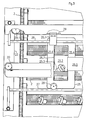
- the transport and Transfer device for the workpieces W a horizontal conveyor in the form of a conveyor belt 20, the conveyor level at an angle ⁇ transverse to the conveying direction each tub 2 in the transfer position is inclined. Between the frame-side longitudinal edge of the conveyor belt 20 and the relevant tub 2, the longitudinal edge of which is scarce is located under a transfer level E, there is one Ramp 25.3, whose upper ramp area is designed as a grid and inclined slightly more than the plane of the conveyor belt 20 is.
- the ramp 25.3 is part of a more detailed below described carriage.
- a sensor in the form of a light barrier 22a, 22b gives a short signal each workpiece W that slides over the ramp surface 21a and a continuous signal as a fault message when a workpiece is on the Ramp surface 21a remains.
- a transfer device ensures that the cyclical and thus at approximately equal intervals over the conveyor belt 20 incoming workpieces W without colliding with each other, get into the respective tub 2 such that they are there come to lie next to each other, cf. 3 and 4.
- the transfer device includes one on the spar 1a of the frame 1 e.g. Height-adjustable via rails such as 23 in FIGS. 2 and 3 attached sled in the form of a frame 25, the via a guide bush 25.1 on an upper guide rod 26 slidably and by a on a lower guide rod 27 running profile roller 28 guided against tilting is.
- a toothed belt is used to move the frame 25 29, the deflection wheels as 29.1 in Fig. 3 and one not shown drive the frame 25 cyclically and with programmable Increment along the guide rods 26 and 27 adjusted.
- each tub 2 has a window 25.2 whose Lower margin bounded by ramp 25.3 mentioned above becomes.
- the window 25.2 slightly larger than the largest dimensions of workpieces to be stored in the workpiece buffer W.
- first vertical leg 25.4 of the Frame 25 closes one best from Figure 4 recognizing partition 25.5 between the conveyor belt 20 and the are located in the transfer level E (see FIG. 2) Tub 2 on.
- second frame leg in the workpiece conveying direction 25.6 ends a guide surface 25.7 that slopes extends against the conveying direction over the conveyor belt (see also Fig. 4).
- the guide surface 25.7 thus ensures in Connection with the bank of the conveyor belt 20 for that each workpiece W through the window opening 25.2 to a location determined by the position of the frame 25 the respective tub 2 arrives.
- Figure 5 shows a similar section of the top view Workpiece buffer as the Fig. 4.
- the frame 1 On the inlet side the frame 1 is, however, an additional arrangement for recognizing and rejecting via the horizontal conveyor 20 incoming, but possibly defective workpieces provided so that the holding capacity of the workpiece buffer not stressed with such workpieces becomes.
- the arrangement comprises a workpiece testing station, e.g. based on the principle of optical pattern recognition can work and accordingly a lighting device 30a on one side of the horizontal conveyor 20 and a pattern checker 30b on the opposite Side of the horizontal conveyor 20 includes. On this workpiece inspection station 30a, 30b closes one of the latter controlled switch.
- the switch is in this Embodiment of an arranged in the partition 25.5 Flap 31, which, controlled by the tester 30b, at Detection of a faulty workpiece according to the Double arrow Pf in the position shown in dashed lines pivots and thus the defective workpiece Wf, as through the arrow f indicated, in the attached to the frame 1 Deflects container 32 for receiving such workpieces.
Landscapes
- Engineering & Computer Science (AREA)
- Mechanical Engineering (AREA)
- Attitude Control For Articles On Conveyors (AREA)
- Intermediate Stations On Conveyors (AREA)
Abstract
Description
- Figur 1
- eine teilweise im Schnitt gehaltene Seitenansicht,
- Figur 2
- die in Fig. 1 entsprechend bezeichnete Einzelheit in vergrößertem Maßstab,
- Figur 3
- eine Ansicht der gleichen Einzelheit in Richtung des Pfeils in Fig. 1 und
- Figur 4
- eine teilweise geschnittene Aufsicht auf diese Einzelheit in Richtung des Pfeils in Fig. 1.
- Figur 5
- eine Aufsicht ähnlich Fig. 4, jedoch mit einer zusätzlichen Werkstückprüfstation.
Claims (22)
- Werkstückzwischenspeicher mit einem Gestell (1), in dem Werkstückaufnahmewannen (2) mittels eines in Schritten antreibbaren Umlaufförderers (3) paternosterartig im Kreis geführt sind, mit einer Werkstückzuführung in Form eines Horizontalförderers (20), der sich oberhalb einer Übergabeebene (E) parallel zu der sich jeweils in oder etwas unter der Übergabeebene (E) befindenden Wanne (2) erstreckt und mit einer Vorrichtung (25 bis 29) zum Überführen aufeinanderfolgender Werkstücke (W) von dem Horizontalförderer (20) in die jeweilige Wanne (2), so daß sie dort nebeneinander zu liegen kommen.
- Werkstückzwischenspeicher nach Anspruch 1, dadurch gekennzeichnet, daß die Förderebene des Horizontalförderers (20) quer zur Förderrichtung auf die jeweils zu beschickende Wanne (2) zu geneigt ist.
- Werkstückzwischenspeicher nach Anspruch 1 oder 2, dadurch gekennzeichnet, daß der Horizontalförderer (20) und ggf. die Überführungseinrichtung (25 bis 29) an dem Gestell (1) höhenverstellbar (bei 23) befestigt ist.
- Werkstückzwischenspeicher nach einem der Ansprüche 1 bis 3, dadurch gekennzeichnet, daß sich zwischen dem Horizontalförderer (20) und der Wanne (2) eine in Richtung letzterer geneigte, gegebenenfalls gitterartig durchbrochene Rampe (25.3) befindet.
- Werkstückzwischenspeicher nach einem der Ansprüche 1 bis 4, dadurch gekennzeichnet, daß die Überführungsvorrichtung einen zu dem Horizontalförderer (20) parallelen, verschiebbaren Schlitten (25 bis 29) umfaßt.
- Werkstückzwischenspeicher nach Anspruch 5, dadurch gekennzeichnet, daß der Schlitten auf einer ersten Führungsstange (26) verschiebbar gelagert und mittels einer zweiten Führungsstange (27) verkippsicher geführt ist.
- Werkstückzwischenspeicher nach einem der Ansprüche 1 bis 6, dadurch gekennzeichnet, daß die Überführungsvorrichtung zwei von einem bis zum anderen Ende der betreffenden Wanne verschiebbare Abweiser (25.4, 25.6) umfaßt, zwischen denen sich eine Fensteröffnung (25.2) mit an die Werkstückabmessungen angepaßtem Querschnitt befindet.
- Werkstückzwischenspeicher nach Anspruch 7, dadurch gekennzeichnet, daß der in der Werkstückförderrichtung (F) erste Abweiser aus einer Trennwand (25.5) zwischen dem Horizontalförderer (20) und der jeweils zu beschickenden Wanne (2) besteht.
- Werkstückzwischenspeicher nach Anspruch 7 oder 8, dadurch gekennzeichnet, daß der in Werkstückförderrichtung (F) zweite Abweiser aus einer sich von einem Seitenrand der Fensteröffnung (25.2) schräg entgegen der Förderrichtung (F) über den Horizontalförderer (20) erstreckenden Leitfläche (25.6) besteht.
- Werkstückzwischenspeicher nach einem der Ansprüche 7 bis 9, dadurch gekennzeichnet, daß der Fensterquerschnitt mittels mindestens eines Sensors (22a, 22b) überwacht ist.
- Werkstückzwischenspeicher nach einem der Ansprüche 1 bis 10, dadurch gekennzeichnet, daß die Wannen (2) gondelartig pendelnd an dem Umlaufförderer (3) befestigt sind.
- Werkstückzwischenspeicher nach einem der Ansprüche 1 bis 11, dadurch gekennzeichnet, daß der Umlaufförderer aus zwei horizontal beabstandeten, jeweils in einer Vertikalebene laufenden Endlosketten (3) besteht.
- Werkstückzwischenspeicher nach Anspruch 12, dadurch gekennzeichnet, daß die Wannen (2) über ihre Stirnseiten mit den Endlosketten (3) verbunden sind.
- Werkstückzwischenspeicher nach einem der Ansprüche 1 bis 13, dadurch gekennzeichnet, daß die Wannen auf ihrem Umlaufweg eine Reinigungsstation (6) durchlaufen.
- Werkstückzwischenspeicher nach Anspruch 14, dadurch gekennzeichnet, daß die Reinigungsstation ein Tauchbecken (6) ist.
- Werkstückzwischenspeicher nach Anspruch 15, dadurch gekennzeichnet, daß ein Füllstandsmelder den Stand einer Waschflüssigkeit in dem Tauchbecken (6) überwacht.
- Werkstückzwischenspeicher nach einem der Ansprüche 1 bis 16, dadurch gekennzeichnet, daß die Wannen (2) gitterartig durchbrochen sind.
- Werkstückzwischenspeicher nach einem der Ansprüche 1 bis 17, dadurch gekennzeichnet, daß das Gestell (1) verkleidet (vgl. 7) ist.
- Werkstückzwischenspeicher nach Anspruch 18, dadurch gekennzeichnet, daß die Verkleidung (7) einen Absauganschluß (9) hat.
- Werkstückzwischenspeicher nach einem der Ansprüche 1 bis 19, dadurch gekennzeichnet, daß das Gestell (1) fahrbar (vgl. 5) ist.
- Werkstückzwischenspeicher nach einem der Ansprüche 1 bis 20, dadurch gekennzeichnet, daß an dem Gestell (1) ein Entnahmetisch (10) höhenverstellbar befestigt ist.
- Werkstückzwischenspeicher nach einem der Ansprüche 1 bis 21, dadurch gekennzeichnet, daß dem Horizontalförderer (20) bezogen auf die Werkstückförderrichtung vor der Überführungsvorrichtung (25 bis 29), eine Werkstückprüfstation (30a, 30b) zugeordnet ist, auf die eine von dieser Werkstückprüfstation gesteuerte Weiche (31) folgt, die Werkstücke (Wf), die nicht in Ordnung sind, aussondert.
Applications Claiming Priority (4)
| Application Number | Priority Date | Filing Date | Title |
|---|---|---|---|
| DE19652948 | 1996-12-19 | ||
| DE19652948 | 1996-12-19 | ||
| DE19749396A DE19749396A1 (de) | 1996-12-19 | 1997-11-07 | Werkstückzwischenspeicher |
| DE19749396 | 1997-11-07 |
Publications (2)
| Publication Number | Publication Date |
|---|---|
| EP0849198A2 true EP0849198A2 (de) | 1998-06-24 |
| EP0849198A3 EP0849198A3 (de) | 1999-03-10 |
Family
ID=26032438
Family Applications (1)
| Application Number | Title | Priority Date | Filing Date |
|---|---|---|---|
| EP97122451A Withdrawn EP0849198A3 (de) | 1996-12-19 | 1997-12-18 | Werkstückzwischenspeicher |
Country Status (1)
| Country | Link |
|---|---|
| EP (1) | EP0849198A3 (de) |
Cited By (2)
| Publication number | Priority date | Publication date | Assignee | Title |
|---|---|---|---|---|
| DE10213721A1 (de) * | 2002-03-26 | 2003-11-27 | Modular Automation Gmbh | Fördersystem zum Entstapeln, Positionieren und Stapeln von Werkstückträgern, insbesondere von mit Werkstücken beladenen Werkstückträgern zur Versorgung von Werkzeugmaschinen mit den Werkstücken |
| WO2010128113A1 (de) | 2009-05-06 | 2010-11-11 | Rotzinger Ag | Zwischenspeicher |
Family Cites Families (4)
| Publication number | Priority date | Publication date | Assignee | Title |
|---|---|---|---|---|
| US3546965A (en) * | 1967-07-12 | 1970-12-15 | Gen Foods Corp | Device for changing the timing of cam driven linkages |
| US4142626A (en) * | 1977-06-08 | 1979-03-06 | Paper Converting Machine Company | Accumulator for wound paper logs |
| JPS6123016A (ja) * | 1984-07-09 | 1986-01-31 | Terada Seisakusho:Kk | 大海貯蔵装置 |
| DE19519792A1 (de) * | 1995-05-30 | 1996-12-05 | Paul Ritzau Pari Werk Gmbh Med | Verteiler und Befüllanlage |
-
1997
- 1997-12-18 EP EP97122451A patent/EP0849198A3/de not_active Withdrawn
Cited By (3)
| Publication number | Priority date | Publication date | Assignee | Title |
|---|---|---|---|---|
| DE10213721A1 (de) * | 2002-03-26 | 2003-11-27 | Modular Automation Gmbh | Fördersystem zum Entstapeln, Positionieren und Stapeln von Werkstückträgern, insbesondere von mit Werkstücken beladenen Werkstückträgern zur Versorgung von Werkzeugmaschinen mit den Werkstücken |
| DE10213721B4 (de) * | 2002-03-26 | 2006-12-28 | Modular Automation Gmbh | Fördersystem zum Entstapeln, Positionieren und Stapeln von Werkstückträgern, insbesondere von mit Werkstücken beladenen Werkstückträgern zur Versorgung von Werkzeugmaschinen mit den Werkstücken |
| WO2010128113A1 (de) | 2009-05-06 | 2010-11-11 | Rotzinger Ag | Zwischenspeicher |
Also Published As
| Publication number | Publication date |
|---|---|
| EP0849198A3 (de) | 1999-03-10 |
Similar Documents
| Publication | Publication Date | Title |
|---|---|---|
| DE69304356T2 (de) | Postvorrichtung | |
| EP1390281A1 (de) | Zwischenspeichervorrichtung und ein verfahren zum transport von gegenständen | |
| DE4191062C2 (de) | Vorrichtung zum Bearbeiten von Werkstücken, insbesondere von Leiterplatten | |
| EP2976277B1 (de) | Verfahren und vorrichtung zum abtransportieren von packungsbehältern | |
| DE2855982C2 (de) | ||
| DE2716334A1 (de) | Verfahren zum erlangen eines gegenstandes aus einem lagerregal o.dgl. und zum weiterleiten desselben sowie vorrichtung zur ausuebung des verfahrens | |
| DE4205923C2 (de) | Vorrichtung zum Abstapeln von Schalen oder schalenähnlichen Gegenständen, insbesondere Geschirrschalen | |
| DE10240629A1 (de) | Kommissioniereinrichtung | |
| DE3107437A1 (de) | Einrichtung zum beschicken eines werkzeugmaschinenauflagetisches | |
| DE1756380A1 (de) | Verfahren und Vorrichtung zur UEbergabe von Guetern zwischen in Bewegung befindlichenFoerderern | |
| DE1782649B1 (de) | Vorrichtung zum handhaben und behandeln, insbesondere zum spuelen von behaeltern | |
| CH670809A5 (de) | ||
| EP0822739B1 (de) | Automatisierte Vorrichtung zum Prüfen von Leiterplatten | |
| EP0371232B1 (de) | Verfahren zum stufenförmigen Gruppieren von Produkten und Vorrichtung zur Durchführung des Verfahrens | |
| DE19926624A1 (de) | Skidrahmen zum Fördern von Werkstücken, insbesondere von Fahrzeugkarosserien, und Drehvorrichtung zum Drehen eines solchen Skidrahmens | |
| DE19749396A1 (de) | Werkstückzwischenspeicher | |
| DE2717586C2 (de) | Ortsbeweglicher Speicher zur Aufnahme und zum Transport von Werkstücken | |
| DE102016225483B4 (de) | Fördervorrichtung | |
| DE2658664A1 (de) | Vorrichtung und verfahren zum transport von material | |
| DE4033184A1 (de) | Umlaufregallager-system | |
| DE4124291C2 (de) | Einrichtung zum Transport von Stückgütern, insbesondere Bauteilen | |
| DE3437004A1 (de) | Fertigungsdurchlaufsystem | |
| DE2743398C2 (de) | Gerät zum Schichtenpalettieren von Behältern, insbesondere von Flaschenkästen | |
| DE4010698C1 (de) | ||
| DE3408678C2 (de) | Vorrichtung zum Entnehmen von Leisten aus Fächern |
Legal Events
| Date | Code | Title | Description |
|---|---|---|---|
| PUAI | Public reference made under article 153(3) epc to a published international application that has entered the european phase |
Free format text: ORIGINAL CODE: 0009012 |
|
| AK | Designated contracting states |
Kind code of ref document: A2 Designated state(s): AT BE CH DE DK ES FI FR GB GR IE IT LI LU MC NL PT SE |
|
| AX | Request for extension of the european patent |
Free format text: AL;LT;LV;MK;RO;SI |
|
| PUAL | Search report despatched |
Free format text: ORIGINAL CODE: 0009013 |
|
| AK | Designated contracting states |
Kind code of ref document: A3 Designated state(s): AT BE CH DE DK ES FI FR GB GR IE IT LI LU MC NL PT SE |
|
| AX | Request for extension of the european patent |
Free format text: AL;LT;LV;MK;RO;SI |
|
| AKX | Designation fees paid | ||
| STAA | Information on the status of an ep patent application or granted ep patent |
Free format text: STATUS: THE APPLICATION IS DEEMED TO BE WITHDRAWN |
|
| 18D | Application deemed to be withdrawn |
Effective date: 20000106 |
|
| REG | Reference to a national code |
Ref country code: DE Ref legal event code: 8566 |