EP0849014B1 - Method of controlling a transfer device for intermittent workpiece transport - Google Patents
Method of controlling a transfer device for intermittent workpiece transport Download PDFInfo
- Publication number
- EP0849014B1 EP0849014B1 EP97121900A EP97121900A EP0849014B1 EP 0849014 B1 EP0849014 B1 EP 0849014B1 EP 97121900 A EP97121900 A EP 97121900A EP 97121900 A EP97121900 A EP 97121900A EP 0849014 B1 EP0849014 B1 EP 0849014B1
- Authority
- EP
- European Patent Office
- Prior art keywords
- transfer
- transfer rail
- control device
- operating mode
- drive
- Prior art date
- Legal status (The legal status is an assumption and is not a legal conclusion. Google has not performed a legal analysis and makes no representation as to the accuracy of the status listed.)
- Expired - Lifetime
Links
Images


Classifications
-
- B—PERFORMING OPERATIONS; TRANSPORTING
- B21—MECHANICAL METAL-WORKING WITHOUT ESSENTIALLY REMOVING MATERIAL; PUNCHING METAL
- B21D—WORKING OR PROCESSING OF SHEET METAL OR METAL TUBES, RODS OR PROFILES WITHOUT ESSENTIALLY REMOVING MATERIAL; PUNCHING METAL
- B21D43/00—Feeding, positioning or storing devices combined with, or arranged in, or specially adapted for use in connection with, apparatus for working or processing sheet metal, metal tubes or metal profiles; Associations therewith of cutting devices
- B21D43/02—Advancing work in relation to the stroke of the die or tool
- B21D43/04—Advancing work in relation to the stroke of the die or tool by means in mechanical engagement with the work
- B21D43/05—Advancing work in relation to the stroke of the die or tool by means in mechanical engagement with the work specially adapted for multi-stage presses
- B21D43/055—Devices comprising a pair of longitudinally and laterally movable parallel transfer bars
Definitions
- the invention relates to a method for switching a transfer device in Emergency operating mode with the features of the preamble of claim 1.
- multi-station presses for example body presses or the like Transfer devices with which workpieces are transported from stage to stage become.
- transfer devices usually have two parallel ones Transfer rails, between which spaced crossbars with Holding means, such as, for example, suction spiders or the like, are held.
- Holding means such as, for example, suction spiders or the like.
- the Workpiece transport takes place through a combined lifting, feeding and Lowering movement of the transfer rails (two-axis transfer).
- crossbeams In addition to the lifting, lowering and feed movements, crossbeams also perform one Cross movement off (three-axis transfer with vertical movement for lifting / lowering, Longitudinal movement to perform a transfer step and cross movement to open and close).
- a three-axis transfer is already known in which as drives for the movements in the three movement axes Linear motors are provided.
- the linear motors are controlled separately, with the linear motors one Transport rail synchronous to the linear motors of the other transport rail as well as press synchronized become.
- the transfer device which can be designed as a two or three-axis transfer can, has at least one, preferably two mutually parallel transfer rails on, in at least one axial direction, for example in the "open / close" direction, the means towards and away from each other, actuated by means of direct electric drives become.
- the respective transfer rail becomes parallel in the transverse direction of several acting electric direct drives driven with their respective output attack the transfer rail.
- the direct drives are spaced apart and over distributed the length of the transfer rail e.g. are three or more direct drives for each Axis provided.
- the control device provided for actuation controls the one axis associated direct drives to match, so that the transfer rail on their entire length performs the specified movement uniformly.
- the Control device sensor signals, for example via the current position of the transfer rail, see above that position control can be obtained.
- the control device has in addition to its regular Operating mode in which it causes the transfer rail (s), preferably in the specified cycle along one programmable or otherwise adjustable transfer curve to move to an emergency mode in which they at least one of the connected and to be operated synchronously
- Direct drives are essentially force-free switches free of forces.
- Such an error can exist, for example, if an assigned to the linear actuator in question Position sensor emits an invalid signal. Becomes recognized this, the assigned direct drive becomes very quickly switched off. This prevents that he works against the other direct drives and the Blocked or blocked movement of the transfer rail. If a single drive fails, the motion sequence can continued until a safe state is reached become.
- the communication system (bus, star, ring) between central control and intelligent drives is designed so that if one individual fails Drive remains operational.
- the control device controls the remaining direct drives in the Emergency mode continues, however, so that the movement of the Transfer rail is continued at least until the Holding means led out of the workstations are. Because of the quick release of power from the This can be done with the direct drive affected by the accident remaining linear motors with sufficient speed done, which are designed for this.
- the transfer rail is in an axis of several, preferably more than three direct drives is the loss of performance in the event of failure and after activating a direct drive, low that the transfer rail is removed from the danger area can be.
- the direct drives in the emergency operating mode also for a short time with excessive power operate. This is particularly the case if the Operation of the transfer device is not over a few cycles away but only continues until the transfer rails and / or the holding means in in a safe position.
- the direct drives assigned to an axis point preferably uniform performance, so that emergency operation in the event of failure of any direct drive leads to tolerable conditions.
- the direct drives are preferably efficient dimensioned so that if a direct drive fails the full required total output or at least provide sufficient performance.
- the transfer rail of the transfer device according to the invention is preferably particularly rigid, to ensure that even if a Direct drive no elastic bends occur, leading to a collision between transfer rail and Tool.
- the bending stiffness, for example, in Lateral direction is increased so far that the natural frequency a mounting rail section, which extends from one worker over a fancy to that next working direct drive extends, is larger than the lowest excitation frequency resulting from the lateral movement in the emergency mode results.
- the movement of the transfer rail can be in the emergency mode deviate from the motion curve that the Transfer rail runs during normal operation.
- the movement curve during emergency operation be determined that the fastest possible exit from the Workstations is made possible. This may happen with a pure lateral movement of the transfer rail can be achieved.
- too attempted during emergency operation which during regular operation passing curve at least within a predetermined Tolerance to follow.
- the direct drives are preferably electrical Linear motors, but also hydraulic or others electrically controllable direct drives are used can.
- the Direct drives or the control device can Monitor device for the detection of error states be provided.
- the monitor device can be part of the Control device or formed separately from this and is used in the event of a system failure direct drive that can no longer be controlled correctly and the emergency mode with the other direct drives initiate.
- a further increase in operational security will by using a redundant communication system between the central control and the intelligent Drives reached. Reliability is further increased through redundant execution of the central Control.
- the control device preferably contains separate ones Control units, each assigned to a direct drive are.
- the control units subordinate to a central unit communicate with each other and with the Central unit via a data transmission system, the one Can have ring structure or bus structure. To avoid of subsequent failures of larger system parts failed transmission sections switched to inactive become. You can also use the entire system or parts of which can be designed redundantly by stand-by units be provided, the operation in the event of a fault take.
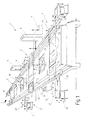
- a multi-station press 1 is schematic indicated, the several in the direction of T in succession arranged press stations 2, 3, 4 and possibly has further press stations, not shown.
- the Workstations 3, 4 assigned plungers 6, 7 only indicated in dashed lines, with tappet guides, Ram drives and press frames for simplification are omitted.
- the press frame is just through stands 8, 9 shown by way of example and in section, 10 indicated.
- Press station for transporting workpieces from the press station Press station in which tools 12, 13, 14 are arranged are a three-axis transfer device 15.
- the Workpiece transport may take place between the press stations 2, 3, 4 arranged intermediate shelves 17, 18, 19.
- the transfer device 15 has two along the Passage direction T extending, parallel to each other Transfer rails 21, 22, the holding means 23 for Carrying and storing the workpieces.
- the transfer rails 21, 22 are with respect to a vertical longitudinal median plane the multi-station press 1 inclusive their drives are mirror-symmetrical to each other. The following description of the transfer rail 21 applies therefore correspondingly for the transfer rail 22.
- the transfer rail 21 is in the direction of T as well as in the vertical direction V and on the center of the multi-station press 1 to and from this, that is in Transverse direction Q, movably mounted.
- the transfer rail 21 in the longitudinal direction (clock direction T) is used for a longitudinal slide guide.
- This will formed by a longitudinal beam 25 on which the transfer rail 21 is mounted for longitudinal displacement.
- the transfer rail 21 in the longitudinal direction serve electrical Linear motors between the side members 25 and the transfer rail 21 act and as direct drives are trained. Over the length of the side member 25 can be distributed over several linear motors. In principle are also controlled or regulated hydraulic drives possible.
- position control position-sensing Sensors are provided which determine the relative position of the Characteristic transfer rail 21 with respect to the longitudinal beam 25 Give signal.
- the longitudinal beam 25 is of several, in the longitudinal direction spaced-apart cross slides 26, 27 worn, the output of linear motors 28, 29 for form the transverse direction Q.
- the linear motors 28, 29 are provided with sensors, not shown, a Issue position signal.
- the Linear motors 28, 29 each on lifting units 31, 32 kept, also by means of electric linear motors or other direct drives can be operated.
- the transfer device is used to improve clarity 15 separately illustrated in FIG. 2, wherein deviating from the transfer device described above on the longitudinal member 25, which is divided several times here not a continuous transfer rail, but individual ones Carriage units 33 are mounted for longitudinal displacement, each with its own linear drive are driven. Each carriage unit 33 registers Holding means 23.
- the linear motor 28 is illustrated. He has a primary part serving as an output 281 and a secondary part 282 formed as a stator, the in corresponding grooves of the ferromagnetic stator Short circuit conductor 283 contains. In grooves of the ferromagnetic Primary part 281 embedded windings phase-shifted (U, V, W; U ', V', W '). If necessary can instead of such a single comb motor also a double comb motor, a solenoid motor or a Synchronous motor with permanent magnetic excitation is used become.
- the advantage of the asynchronous motor is in the fact that it is particularly easy to switch off leaves.
- control device 36 the press controller 37 is subordinate.
- the control device 36 has one Central unit 38 to which via an optical fiber ring line 39 control units 41, 42, 43, 44 and 45 as well as other control units, not shown are.
- the optical fiber ring line 39 is used for data exchange between the central unit 38 and the control units 41 to 45.
- Each control unit 41 to 45 controls an electric linear motor 28, 29, for position feedback, each with a linear position measuring unit 46, 47 is provided.
- a monitor unit M On the control units 41 to 45 and / or on the Central unit 38 is a monitor unit M in each case trained the correct functioning of each Unit of the connected linear drive (28, 29) and connected sensors (46, 47) are monitored.
- the Monitor unit M can also be part of control units 41 to 45 or the central unit 38. E.g. can the Monitor function from the control unit or from one Program section to be provided, which becomes a program the control or central unit 41 to 35, 38 belongs.
- control units 41 to 45 and the central unit 38 influence the Monitor units M the operation of the control device 36 Not.
- the control units 41 to 45 received from the Central processing unit 38 via the optical fiber ring line 39 control signals for positioning the transfer rail 21.
- the control units 41 to 45 set this Control commands and regulate the respectively connected Linear motors so that the specified movement is achieved becomes.
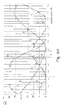
- Figures 6 and 6A illustrate relative to FIG a press revolution angular ranges in which the transfer device 15 completed movements must and their timings. More than a half Angular range 51 taking eccentric shaft revolution indicates the downward stroke of the press ram e.g. in a drawing stage or in another press stage. The remaining angular range 52 characterizes the Return stroke of the ram. The control is on this movement the linear drives synchronized.
- the transfer rails 21, 22 guide a feed stroke in an angular range 53 out of a workpiece in the open tool leads. The transfer rails begin before the feed stroke ends 21, 22 in the angular range 54.
- the transfer rails 21, 22 begin in the Angular range 55 to move away from each other to release the closing tool.
- the stamp is moved further downwards, begins during the Opening movement (angular range 55) of the transfer rails 21, 22 whose return stroke 66 at an angular position of about 110 °.
- the return stroke 66 Tranferschienen 21, 22, these begin with themselves opening tool in an angular range 57 again close to grasp the workpiece and open Raise die in area 58 and in the next cycle continue to convey in the angular range 53.
- the angular range proves to be particularly critical 55, in which the opening transfer rails the Must have left the working area of the ram while the tool closes. If this does not succeed, can the press ram because of the relatively large flywheels do not stop abruptly, so that there is a collision between the tool and the transfer rails 21, 22 or the holding means 23 comes.
- the safe or collision-free position P can on the movement curve can be achieved, which otherwise also with proper Operation is going through.
- the definition of different Curves KN for emergency operation, on which a collision-free Position P faster or with less effort is achievable is possible. With the emergency operation achieved that only a small security angle between the removal of the holding means 23 from the Tool and closing the tool required is. Then the working speed of the press increase.
- the Transfer rail 21 has such a lateral rigidity on that they are relative at the occurring large accelerations in the direction of the Q axis deflects significantly. In addition, it has a stiffness reserve on, which prevents the transfer rail 21 in the event of failure of a linear motor, e.g. the Linear motor 29, due to the now larger distance between the active linear motors 28 and 29a at the side Accelerate bends elastically, as at 61 indicated.
- the increased rigidity of the transfer rail 21 thus enables that in the event of a linear motor failure its driving force from the neighboring linear motors 28, 29a and the other linear motors and is introduced into the transfer rail 21.
- the control device takes a similar emergency operation 36 in the event of failure of parts of the optical fiber ring line 39 a, with appropriate interpretation of the information transmission system only for failure one or fewer drive units.
- the Linear motors that remain active go into emergency operation over and pose during the particularly critical opening phase (55 in Fig. 6) collision-free operation for sure.
- Fig. 7 is a modified, as a two-axis transfer trained transfer device 15 'illustrates in which the transfer rails 21, 22 only in the direction of passage T and in the vertical direction V are movable.
- the transfer rails 21, 22 For driving in the direction of travel T and as a lifting unit for Lifting and lowering in the vertical direction serve electrical purposes Linear drives, as in principle and as an example in Fig. 3 illustrates.
- suction spiders 63 With such a two-axis transfer device 15 'it depends on the holding means 23 (suction spiders 63) in the event of an error when closing the To bring the tool out of it in time.
- a controller 36 for direct electric drives 28, 29 of a transfer device 15 contains at least one Monitor device M, the malfunction of a direct drive 28, 29 the control device 36 in an emergency operating mode toggles.
- the switches in the emergency mode Control device 36 to those affected by the error Linear drive is powerless and controls the remaining ones Direct drives preferably with full or slightly excessive Performance so that there is no collision between the forming tool and the transfer device 15 after which the press is preferably shut down becomes.
Description
Die Erfindung betrifft ein Verfahren zum Schalten einer Transfervorrichtung in Notbetriebsart mit den Merkmalen des Oberbegriffes des Patentanspruches 1.The invention relates to a method for switching a transfer device in Emergency operating mode with the features of the preamble of claim 1.
Insbesondere Mehrstationenpressen, bspw Karosseriepressenoder dergl., weisen Transfervorrichtungen auf, mit denen Werkstücke von Stufe zu Stufe weitertransportiert werden. Dazu haben solche Transfervorrichtungen meist zwei zueinander parallele Transferschienen, zwischen denen voneinander beabstandete Quertraversen mit Festhaltemitteln, wie bspw. Saugerspinnen oder dergl., gehalten sind. Der Werkstücktransport erfolgt durch eine kombinierte Hebe-, Vorschub- und Senkbewegung der Transferschienen(Zweiachstransfer).In particular, multi-station presses, for example body presses or the like Transfer devices with which workpieces are transported from stage to stage become. For this purpose, such transfer devices usually have two parallel ones Transfer rails, between which spaced crossbars with Holding means, such as, for example, suction spiders or the like, are held. The Workpiece transport takes place through a combined lifting, feeding and Lowering movement of the transfer rails (two-axis transfer).
Darüber hinaus sind Transfervorrichtungen bekannt, bei denen anstelle der Quertraversen an den Transferschienen gehaltene Festhaltemittel vorgesehen sind. Die Quertraversen führen hier neben der Hebe-Senk- und Vorschubbewegung noch eine Querbewegung aus (Dreiachstransfer mit Vertikalbewegung zum Heben/Senken, Längsbewegung zum Ausführen eines Transferschrittes und Querbewegung zum Öffnen und Schließen).In addition, transfer devices are known in which instead of Cross members on the transfer rails holding means are provided. The In addition to the lifting, lowering and feed movements, crossbeams also perform one Cross movement off (three-axis transfer with vertical movement for lifting / lowering, Longitudinal movement to perform a transfer step and cross movement to open and close).
Es ist bereits ein Dreiachstransfer bekannt, bei dem als Antriebe für die Bewegungen in den drei Bewegungsachsen Linearmotoren vorgesehen sind. Die Linearmotoren werden separat angesteuert, wobei die Linearmotoren einer Transportschiene synchron zu den Linearmotoren der anderen Transportschiene sowie pressensynchron angesteuert werden.A three-axis transfer is already known in which as drives for the movements in the three movement axes Linear motors are provided. The linear motors are controlled separately, with the linear motors one Transport rail synchronous to the linear motors of the other transport rail as well as press synchronized become.
Während der Antrieb von Transferschienen mit Linearmotoren als Direktantriebe zu kostengünstigen, baulich einfachen Transfervorrichtungen führt, die einen flexiblen Einsatz gestatten, besteht bei einem möglichen Ausfall einzelner Systemkomponenten die Gefahr, daß die Transferschiene und/oder andere Elemente der Transfervorrichtung, wie bspw. Quertraversen, nicht die gewünschte Bewegung ausführen und bspw. eine Arbeitsstation nach Aufnahme oder Ablage eines Werkstückes nicht rechtzeitig verlassen. Bei Mehrstationenpressen kann dies zu einer ernsthaften Beschädigung der Transferschiene oder sonstiger Elemente und im schlimmsten Falle der gesamten Transfervorrichtung und/oder von Werkzeugen führen.While driving transfer rails with linear motors as direct drives at low cost, structurally leads simple transfer devices that are flexible Allow use, there is one possible Failure of individual system components the risk that the Transfer rail and / or other elements of the transfer device, such as cross beams, not the desired one Carry out movement and, for example, a work station Not picking up or storing a workpiece in time leave. In the case of multi-station presses, this can lead to one serious damage to the transfer rail or other Elements and, at worst, the whole Guide the transfer device and / or tools.
Aus der DE 44 22 719 A1 ist eine Sicherheitseinrichtung für ein flexibles Transfersystem für Pressen bekannt geworden, bei dem die Transferschiene eines Dreiachstransfers an einem vorgespannten Federspeicher gelagert ist. Dieser ist im Ruhezustand in seiner Spannstellung arretiert und erzeugt, wenn er ausgelöst wird, eine schnelle seitliche Bewegung der Transferschiene. Zum Arretieren des Federspeichers dient ein Kniehebelsystem, das im Fehlerfalle elektromagnetisch ausgelöst wird. Die sich nun einstellende schnelle Querbewegung der Transferschiene führt diese aus dem Gefahrenbereich heraus. DE 44 22 719 A1 describes a safety device for a flexible transfer system for presses became known, in which the transfer rail one Three-axis transfers on a preloaded spring mechanism is stored. This is in its tensioned position in the idle state locked and generated when triggered a quick sideways movement of the transfer rail. To the A toggle lever system serves to lock the spring accumulator, that is triggered electromagnetically in the event of a fault. The now quick transverse movement of the transfer rail leads them out of the danger area.
Für eine einzelne Transferschiene sind in der Regel mehrere Federspeicher erforderlich, die insgesamt einen nennenswerten Aufwand und eine beachtliche zusätzliche Masse verursachen, die es beim Transfer zu beschleunigen und abzubremsen giltThere are usually several spring accumulators for a single transfer rail required, the overall a significant effort and a considerable cause additional mass to accelerate and brake it during transfer applies
Davon ausgehend ist es Aufgabe der Erfindung, ein Verfahren zu schaffen für eine fehlersichere Transfervorrichtung, die ein gutes dynamisches Verhalten aufweistBased on this, it is an object of the invention to provide a method for fail-safe transfer device that exhibits good dynamic behavior
Diese Aufgabe wird durch das Verfahren nach Patentanspruch 1 gelöst.This object is achieved by the method according to claim 1.
Die Transfervorrichtung, die als Zwei- oder als Dreiachstransfer ausgebildet sein kann, weist wenigstens eine, vorzugsweise zwei zueinander parallele Transferschienen auf, die in wenigstens einer Achsrichtung, bspw in der Richtung "Öffnen/Schließen", das heißt aufeinander zu und voneinander weg, mittels elektrischer Direktantriebe betätigt werden. Dabei wird die jeweilige Transferschiene in Querrichtung von mehreren parallel wirkenden elektrischen Direktantrieben angetrieben, die mit ihrem jeweiligen Abtrieb an der Transferschiene angreifen. Die Direktantriebe sind voneinander beabstandet und über die Länge der Transferschiene verteilt Bspw. sind drei oder mehr Direktantriebe für jede Achse vorgesehen.The transfer device, which can be designed as a two or three-axis transfer can, has at least one, preferably two mutually parallel transfer rails on, in at least one axial direction, for example in the "open / close" direction, the means towards and away from each other, actuated by means of direct electric drives become. The respective transfer rail becomes parallel in the transverse direction of several acting electric direct drives driven with their respective output attack the transfer rail. The direct drives are spaced apart and over distributed the length of the transfer rail e.g. are three or more direct drives for each Axis provided.
Die zur Ansteuerung vorgesehene Steuereinrichtung steuert die zu einer Achse gehörigen Direktantriebe übereinstimmend an, so daß die Transferschiene über ihre gesamte Länge die vorgegebene Bewegung einheitlich ausführt. Vorzugsweise erhält die Steuereinrichtung Sensorsignale, bspw über die aktuelle Position der Transferschiene, so daß eine Positionsregelung erhalten werden kann. The control device provided for actuation controls the one axis associated direct drives to match, so that the transfer rail on their entire length performs the specified movement uniformly. Preferably, the Control device sensor signals, for example via the current position of the transfer rail, see above that position control can be obtained.
Die Steuereinrichtung weist neben ihrer regulären Betriebsart, in der sie die Transferschiene(n) veranlaßt, sich im vorgegebenen Takt entlang einer vorzugsweise programmierbaren oder sonstwie einstellbaren Transferkurve zu bewegen, eine Notbetriebsart auf, in der sie wenigstens einen der angeschlossenen und synchron zu betätigenden Direktantriebe kräftefrei oder im wesentlichen kräftefrei schaltet. Ein solcher Fehler kann bspw. vorliegen, wenn ein dem betreffenen Linearantrieb zugeordneter Positionssensor ein ungültiges Signal abgibt. Wird dies erkannt, wird der zugeordnete Direktantrieb sehr schnell kräftefrei geschaltet. Dadurch wird verhindert, daß er gegen die anderen Direktantriebe arbeitet und die Bewegung der Transferschiene blockiert oder behindert. Bei Ausfall eines einzelnen Antriebes kann der Bewegungsablauf bis zum Erreichen eines sicheren Zustandes weitergeführt werden.The control device has in addition to its regular Operating mode in which it causes the transfer rail (s), preferably in the specified cycle along one programmable or otherwise adjustable transfer curve to move to an emergency mode in which they at least one of the connected and to be operated synchronously Direct drives are essentially force-free switches free of forces. Such an error can exist, for example, if an assigned to the linear actuator in question Position sensor emits an invalid signal. Becomes recognized this, the assigned direct drive becomes very quickly switched off. This prevents that he works against the other direct drives and the Blocked or blocked movement of the transfer rail. If a single drive fails, the motion sequence can continued until a safe state is reached become.
Das Kommunikationssystem (Bus, Stern, Ring) zwischen der zentralen Steuerung und den intelligenten Antrieben ist so ausgeführt, daß es bei Ausfall eines einzelnen Antriebes weiter betriebsfähig bleibt. Die Steuereinrichtung steuert die verbleibenden Direktantriebe in der Notbetriebsart jedoch weiter an, so daß die Bewegung der Transferschiene wenigstens fortgesetzt wird, bis die Festhaltemittel aus den Arbeitsstationen herausgeführt sind. Wegen der schnellen Kraftfreischaltung des von der Havarie betroffenen Direktantriebes kann dies mit den verbleibenden Linearmotoren mit ausreichender Geschwindigkeit erfolgen, wobei diese dafür ausgelegt sind. Insbesondere, wenn die Transferschiene in einer Achse von mehreren, vorzugsweise mehr als drei Direktantrieben bewegt wird, ist die Leistungseinbuße bei Ausfall und nach Kräftefreischalten eines Direktantriebes gering, so daß die Transferschiene aus dem Gefahrenbereich entfernt werden kann. Gegebenenfalls können die Direktantriebe in der Notbetriebsart auch kurzzeitig mit überhöhter Leistung betrieben werden. Dies insbesondere, wenn der Betrieb der Transfervorrichtung nicht über einige Takte hinweg sondern nur so lange fortgesetzt wird, bis sich die Transferschienen und/oder die Festhaltemittel in einer sicheren Position befinden.The communication system (bus, star, ring) between central control and intelligent drives is designed so that if one individual fails Drive remains operational. The control device controls the remaining direct drives in the Emergency mode continues, however, so that the movement of the Transfer rail is continued at least until the Holding means led out of the workstations are. Because of the quick release of power from the This can be done with the direct drive affected by the accident remaining linear motors with sufficient speed done, which are designed for this. Especially if the transfer rail is in an axis of several, preferably more than three direct drives is the loss of performance in the event of failure and after activating a direct drive, low that the transfer rail is removed from the danger area can be. If necessary, the direct drives in the emergency operating mode also for a short time with excessive power operate. This is particularly the case if the Operation of the transfer device is not over a few cycles away but only continues until the transfer rails and / or the holding means in in a safe position.
Die einer Achse zugeordneten Direktantriebe weisen vorzugsweise eine einheitliche Leistungsfähigkeit auf, so daß der Notbetrieb bei Ausfall eines beliebigen Direktantriebes jeweils zu tolerierbaren Verhältnissen führt. Vorzugsweise sind die Direktantriebe in ihrer Leistungsfähigkeit so bemessen, daß sie bei Ausfall eines Direktantriebes noch die volle erforderliche Gesamtleistung oder wenigstens eine ausreichende Leistung liefern.The direct drives assigned to an axis point preferably uniform performance, so that emergency operation in the event of failure of any direct drive leads to tolerable conditions. The direct drives are preferably efficient dimensioned so that if a direct drive fails the full required total output or at least provide sufficient performance.
Die Transferschiene der erfindungsgemäßen Transfervorrichtung ist vorzugsweise besonders biegesteif ausgeführt, um sicherzustellen, daß auch bei Ausfall eines Direktantriebes keine elastischen Verbiegungen auftreten, die zu einer Kollision zwischen Transferschiene und Werkzeug führen könnten. Die Biegesteifigkeit bspw. in Seitenrichtung ist dazu so weit erhöht, daß die Eigenfrequenz eines Tragschienenabschnittes, der sich von einem arbeitenden über einen ausgefallenen bis zu dem nächsten arbeitenden Direktantrieb erstreckt, größer ist als die niedrigste Anregungsfrequenz, die sich aus der seitlichen Bewegung in der Notbetriebsart ergibt.The transfer rail of the transfer device according to the invention is preferably particularly rigid, to ensure that even if a Direct drive no elastic bends occur, leading to a collision between transfer rail and Tool. The bending stiffness, for example, in Lateral direction is increased so far that the natural frequency a mounting rail section, which extends from one worker over a fancy to that next working direct drive extends, is larger than the lowest excitation frequency resulting from the lateral movement in the emergency mode results.
Die Bewegung der Transferschiene kann in der Notbetriebsart von der Bewegungskurve abweichen, die die Transferschiene bei regulärem Betrieb durchfährt. Insbesondere kann die Bewegungskurve bei Notbetrieb so festgelegt sein, daß ein schnellstmögliches Verlassen der Arbeitsstationen ermöglicht wird. Dies kann unter Umständen mit einer reinen seitlichen Bewegung der Transferschiene erreicht werden. In der Regel wird jedoch auch bei Notbetrieb versucht, der bei regulärem Betrieb zu durchfahrenden Kurve wenigstens innerhalb einer vorgegebenen Toleranz zu folgen.The movement of the transfer rail can be in the emergency mode deviate from the motion curve that the Transfer rail runs during normal operation. In particular can the movement curve during emergency operation be determined that the fastest possible exit from the Workstations is made possible. This may happen with a pure lateral movement of the transfer rail can be achieved. Usually, however, too attempted during emergency operation, which during regular operation passing curve at least within a predetermined Tolerance to follow.
Die Direktantriebe sind vorzugsweise elektrische Linearmotoren, wobei jedoch auch hydraulische oder andere elektrisch steuerbare Direktantriebe zur Anwendung kommen können.The direct drives are preferably electrical Linear motors, but also hydraulic or others electrically controllable direct drives are used can.
Zur Erfassung von Ausfällen an den Sensoren, den Direktantrieben oder der Steuereinrichtung kann eine Monitoreinrichtung zur Erkennung von Fehlerzuständen vorgesehen sein. Die Monitoreinrichtung kann Teil der Steuereinrichtung oder von dieser getrennt ausgebildet sein und dient dazu, bei einem Ausfall im System den nicht mehr korrekt steuerbaren Direktantrieb zu bestimmen und die Notbetriebsart mit den übrigen Direktantrieben einzuleiten.To detect failures at the sensors, the Direct drives or the control device can Monitor device for the detection of error states be provided. The monitor device can be part of the Control device or formed separately from this and is used in the event of a system failure direct drive that can no longer be controlled correctly and the emergency mode with the other direct drives initiate.
Eine weitere Erhöhung der Betriebssicherheit wird durch Einsatz eines redundanten Kommunikationssystems zwischen der zentralen Steuerung und den intelligenten Antrieben erreicht. Noch gesteigert wird die Ausfallsicherheit durch redundante Ausführung der zentralen Steuerung.A further increase in operational security will by using a redundant communication system between the central control and the intelligent Drives reached. Reliability is further increased through redundant execution of the central Control.
Die Steuereinrichtung enthält vorzugsweise separate Steuereinheiten, die jeweils einem Direktantrieb zugeordnet sind. Die einer Zentraleinheit untergeordneten Steuereinheiten kommunizieren untereinander und mit der Zentraleinheit über ein Datenübertragungssystem, das eine Ringstruktur oder Busstruktur aufweisen kann. Zur Vermeidung von Folgeausfällen größerer Systemteile können ausgefallene Übertragungsabschnitte inaktiv geschaltet werden. Außerdem können das gesamte System oder Teile davon redundant ausgebildet sein, indem Stand-By-Einheiten vorgesehen werden, die im Fehlerfall den Betrieb übernehmen. The control device preferably contains separate ones Control units, each assigned to a direct drive are. The control units subordinate to a central unit communicate with each other and with the Central unit via a data transmission system, the one Can have ring structure or bus structure. To avoid of subsequent failures of larger system parts failed transmission sections switched to inactive become. You can also use the entire system or parts of which can be designed redundantly by stand-by units be provided, the operation in the event of a fault take.
Die Vorteile des Verfahrens ergeben sich entsprechend für eine Mehrstationenpresse beim Schalten in der Betriebsart Notbetrieb.The advantages of the method result accordingly for a multi-station press when switching in the emergency mode.
In der Zeichnung ist ein Ausführungsbeispiel der Erfindung dargestellt. Es zeigen:
- Fig. 1
- eine Mehrstationenpresse mit Dreiachstransfer, in schematisierter, ausschnittsweiser Darstellung unter Weglassung der Stößelführungen und der Stößelantriebe,
- Fig. 2
- den Dreiachstransfer nach Fig. 1 mit als Direktantrieb dienenden Linearmotoren, in perspektivischer, schematisierter Darstellung,
- Fig 3
- einen Asynchron-Linearmotor, wie er als Direktantrieb für den Dreiachstransfer nach Fig 2 verwendbar ist, in schematisierter, vereinfachter Schnittdarstellung,
- Fig. 4
- eine Transferschiene des Dreiachstransfers mit ausgefallenem Linearantrieb, in einer Draufsicht, unter überhöhter Darstellung möglicher dynamischer Übergangsvorgänge,
- Fig. 5
- eine die linearmotoren ansteuernde Steuereinrichtung mit mehreren Steuereinheiten, im Blockschaltbild,
- Fig. 6
- ein Polardiagramm zur Darstellung der zeitlichen bzw. phasenmäßigen Zuordnung von Bewegungen des Dreiachstransfers in Bezug auf einen Pressenumlauf,
- Fig. 6A
- Zeitverläufe der Bewegung der Transferschienen und des Pressenstößels, und
- Fig. 7
- einen mittels elektrischer Linearmotoren angetriebenen Zweiachstransfer in perspektivischer Prinzipdarstellung.
- Fig. 1
- a multi-station press with three-axis transfer, in a schematic, partial representation, omitting the ram guides and the ram drives,
- Fig. 2
- 1 with linear motors serving as direct drive, in a perspective, schematic representation,
- Fig. 3
- an asynchronous linear motor, as it can be used as a direct drive for the three-axis transfer according to FIG. 2, in a schematic, simplified sectional view,
- Fig. 4
- a transfer rail of the three-axis transfer with failed linear drive, in a plan view, with an excessive representation of possible dynamic transition processes,
- Fig. 5
- a control device controlling the linear motors with several control units, in the block diagram,
- Fig. 6
- a polar diagram to show the temporal or phase assignment of movements of the three-axis transfer in relation to a press cycle,
- Figure 6A
- Timings of the movement of the transfer rails and the press ram, and
- Fig. 7
- a two-axis transfer driven by means of electric linear motors in a perspective basic illustration.
In Fig. 1 ist eine Mehrstationenpresse 1 schematisch
angedeutet, die mehrere in Durchlaufrichtung T hintereinander
angeordnete Pressenstationen 2, 3, 4 sowie eventuell
weitere, nicht dargestellte Pressenstationen aufweist.
Zur Verbesserung der Übersichtlichkeit sind den
Arbeitsstationen 3, 4 zugeordnete Stößel 6, 7 lediglich
in gestrichelten Linien angedeutet, wobei Stößelführungen,
Stößelantriebe und Pressenrahmen zur Vereinfachung
weggelassen sind. Der Pressenrahmen ist lediglich durch
beispielhaft und geschnitten dargestellte Ständer 8, 9,
10 angedeutet.In Fig. 1, a multi-station press 1 is schematic
indicated, the several in the direction of T in succession
arranged
Zum Transport von Werkstücken von Pressenstation zu
Pressenstation, in denen Werkzeuge 12, 13, 14 angeordnet
sind, dient eine dreiachsige Transfervorrichtung 15. Der
Werkstücktransport erfolgt gegebenenfalls über zwischen
den Pressenstationen 2, 3, 4 angeordnete Zwischenablagen
17, 18, 19.For transporting workpieces from the press station
Press station in which
Die Transfervorrichtung 15 weist zwei sich längs der
Durchlaufrichtung T erstreckende, zueinander parallele
Transferschienen 21, 22 auf, die Festhaltemittel 23 zur
Aufnahme und Ablage der Werkstücke tragen. Die Transferschienen
21, 22 sind bezüglich einer vertikalen Längsmittelebene
der Mehrstationenpresse 1 einschließlich
ihrer Antriebe spiegelsymmetrisch zueinander ausgebildet.
Die nachfolgende Beschreibung der Transferschiene 21 gilt
deshalb entsprechend für die Transferschiene 22.The
Die Transferschiene 21 ist in Durchlaufrichtung T
sowie in Vertikalrichtung V und auf die Mitte der Mehrstationenpresse
1 hin und von dieser weg, das heißt in
Querrichtung Q, bewegbar gelagert. Zur Lagerung und
Führung der Transferschiene 21 in Längsrichtung (Taktrichtung
T) dient eine Längsschlittenführung. Diese wird
durch einen Längsträger 25 gebildet, an dem die Transferschiene
21 längsverschiebbar gelagert ist. Zum Antrieb
der Transferschiene 21 in Längsrichtung dienen elektrische
Linearmotoren, die zwischen dem Längsträger 25 und
der Transferschiene 21 wirken und als Direktantriebe
ausgebildet sind. Über die Länge des Längsträgers 25
können mehrere Linearmotoren verteilt sein. Prinzipiell
sind hier auch gesteuerte oder geregelte Hydraulikantriebe
möglich. Zur Lageregelung sind positionserfassende
Sensoren vorgesehen, die ein die Relativposition der
Transferschiene 21 in Bezug auf den Längsträger 25 kennzeichnendes
Signal abgeben.The
Der Längsträger 25 ist von mehreren, in Längsrichtung
voneinander beabstandeten Querschlitten 26, 27
getragen, die den Abtrieb von Linearmotoren 28, 29 für
die Querrichtung Q bilden. Die Linearmotoren 28, 29 sind
mit nicht weiter dargestellten Sensoren versehen, die ein
Positionssignal abgeben.The
Zum Heben und Senken der Transferschiene 21 sind die
Linearmotoren 28, 29 jeweils an Hubeinheiten 31, 32
gehalten, die ebenfalls mittels elektrischer Linearmotoren
oder anderer Direktantriebe betrieben sein können.
Zur Verbesserung der Übersichtlichkeit ist die Transfervorrichtung
15 in Fig. 2 separat veranschaulicht, wobei
abweichend von der vorstehend beschriebenen Transfervorrichtung
an dem hier mehrfach unterteilten Längsträger 25
keine durchgehende Transferschiene sondern einzelne
Schlitteneinheiten 33 längsverschiebbar gelagert sind,
die jeweils über einen eigenen Linearantrieb direkt
angetrieben sind. Jede Schlitteneinheit 33 trägt ein
Festhaltemittel 23.To raise and lower the
In Fig. 3 ist der Linearmotor 28 veranschaulicht. Er
weist einen als Abtrieb dienenden Primärteil 281 und
einen als Stator ausgebildeten Sekundärteil 282 auf, der
in entsprechenden Nuten des ferromagnetischen Stators
Kurzschlußleiter 283 enthält. In Nuten des ferromagnetischen
Primärteiles 281 eingebettete Wicklungen werden
phasenversetzt (U, V, W; U', V', W') angesteuert. Bedarfsweise
kann anstelle eines solchen Einzelkammotors
auch ein Doppelkammotor, ein Solenoidmotor oder ein
Synchronmotor mit permanentmagnetischer Erregung verwendet
werden. Der Vorzug des Asynchronmotors liegt
darin, daß er sich besonders einfach kräftefrei schalten
läßt.3, the
Wie aus der schematisierten Ansicht aus Fig. 4
hervorgeht, greifen an der Transferschiene 21 bspw. zur
Bewegung in Querrichtung Q (Öffnen und Schließen) neben
den genannten Linearmotoren 28, 29 weitere Linearmotoren
28a, 29a, 29b, 29c, 29d an, die synchron angesteuert
werden. Dazu dient eine aus Fig. 5 bspw. ersichtliche
Steuereinrichtung 36, die einer Pressensteuerung 37
untergeordnet ist. Die Steuereinrichtung 36 weist eine
Zentraleinheit 38 auf, an die über eine Lichtwellenleiter-Ringleitung
39 Steuereinheiten 41, 42, 43, 44 und 45
sowie weitere, nicht dargestellte Steuereinheiten angeschlossen
sind. Die Lichtwellenleiter-Ringleitung 39
dient dem Datenaustausch zwischen der Zentraleinheit 38
und den Steuereinheiten 41 bis 45. Jede Steuereinheit 41
bis 45 steuert einen elektrischen Linearmotor 28, 29 an,
der zur Lagerückmeldung jeweils mit einer linearen Wegmeßeinheit
46, 47 versehen ist.As from the schematic view from FIG. 4
emerges, access the
An den Steuereinheiten 41 bis 45 und/oder an der
Zentraleinheit 38 ist jeweils eine Monitoreinheit M
ausgebildet, die die korrekte Funktion der jeweiligen
Einheit, des angeschlossenen Linearantriebes (28, 29)
sowie angeschlossener Sensoren (46, 47) überwacht. Die
Monitoreinheit M kann auch Teil der Steuereinheiten 41
bis 45 oder der Zentraleinheit 38 sein. Bspw. kann die
Monitorfunktion von der Steuereinheit oder von einem
Programmabschnitt erbracht werden, der zu einem Programm
der Steuer- oder Zentraleinheit 41 bis 35, 38 gehört.On the
Bei ordnungsgemäßer Funktion der Sensorik der Linearmotoren
der Stromversorgung sowie der Steuereinheiten
41 bis 45 und der Zentraleinheit 38 beeinflussen die
Monitoreinheiten M den Betrieb der Steuereinrichtung 36
nicht. Die Steuereinheiten 41 bis 45 erhalten von der
Zentraleinheit 38 über die Lichtwellenleiter-Ringleitung
39 Steuersignale für die Positionierung der Transferschiene
21. Die Steuereinheiten 41 bis 45 setzen diese
Steuerbefehle um und regeln die jeweils angeschlossenen
Linearmotoren so, daß die vorgegebene Bewegung erreicht
wird.If the sensors of the linear motors function properly
the power supply and the
Die Figuren 6 und 6A veranschaulichen bezogen auf
einen Pressenumlauf Winkelbereiche, in denen die Transfervorrichtung
15 vorgegebene Bewegungen absolviert haben
muß sowie deren Zeitverläufe. Ein mehr als eine halbe
Exzenterwellenumdrehung einnehmender Winkelbereich 51
kennzeichnet den Abwärtshub des Pressenstößels bspw. in
einer Ziehstufe oder auch in einer anderweitigen Pressenstufe.
Der verbleibende Winkelbereich 52 kennzeichnet den
Rückhub des Stößels. Auf diese Bewegung ist die Steuerung
der Linearantriebe synchronisiert. Die Transferschienen
21, 22 führen in einem Winkelbereich 53 einen Zuführhub
aus, der ein Werkstück in das offenstehende Werkzeug
führt. Vor Ende des Zuführhubes beginnen sich die Tranferschienen
21, 22 in dem Winkelbereich 54 abzusenken.
Sobald das Werkstück bei "S" auf dem Unterwerkzeug abgelegt
ist, beginnen sich die Tranferschienen 21, 22 in dem
Winkelbereich 55 voneinander weg zu bewegen, um das sich
schließende Werkzeug freizugeben. Während der Stempel
weiter abwärts bewegt wird, beginnt noch während der
Öffnungsbewegung (Winkelbereich 55) der Transferschienen
21, 22 deren Rückhub 66 bei einer Winkelposition von
ungefähr 110°. Noch während der Rückhubbewegung 66 der
Tranferschienen 21, 22 beginnen diese, sich bei sich
öffnendem Werkzeug in einem Winkelbereich 57 wieder zu
schließen, um das Werkstück zu erfassen und bei offenem
Gesenk in dem Bereich 58 anzuheben und im nächsten Zyklus
in dem Winkelbereich 53 weiterzufördern.Figures 6 and 6A illustrate relative to FIG
a press revolution angular ranges in which the
Als besonders kritisch erweist sich der Winkelbereich 55, in dem die sich öffnenden Transferschienen den Arbeitsbereich des Stößels verlassen haben müssen, während sich das Werkzeug schließt. Gelingt dies nicht, kann der Pressenstößel wegen der in dem Antrieb enthaltenen, relativ großen Schwungmassen nicht abrupt stoppen, so daß es zur Kollision zwischen dem Werkzeug und den Transferschienen 21, 22 bzw. den Festhaltemitteln 23 kommt.The angular range proves to be particularly critical 55, in which the opening transfer rails the Must have left the working area of the ram while the tool closes. If this does not succeed, can the press ram because of the relatively large flywheels do not stop abruptly, so that there is a collision between the tool and the transfer rails 21, 22 or the holding means 23 comes.
Um in solchen Fällen Beschädigungen der Werkzeuge
und der Transfereinrichtung 15 zu vermeiden, überwachen
die Monitoreinrichtungen M die korrekte Funktion der
Transfervorrichtung 15. Wird festgestellt, daß bspw. ein
einzelner Linearmotor nicht korrekt arbeitet oder korrekt
angesteuert wird, so daß es zu einer Kollision kommen
könnte, gibt die betreffende Monitoreinrichtung ein
Fehlersignal an die betreffende Steuereinheit und/oder
das Gesamtsystem ab. Ein solcher auslösender Fehler kann
bspw. ein Sensorsignal bspw. von der linearen Wegmeßeinrichtung
47 sein, das bezüglich der übrigen Sensorsignale
außerhalb einer vorgegebenen Toleranz liegt. In
diesem Fall geht die Steuereinrichtung 36 in eine Notbetriebsart
über. Diese dient dazu, insbesondere in dem
Winkelbereich 55 die Transferscheinen 21, 22 und die
angeschlossenen Festhaltemittel 23 aus dem sich schließenden
Werkzeug herauszufahren. Dazu wird der von dem
Fehler betroffene Linearantrieb (im Beispiel der Linearmotor
29) kräftefrei geschaltet, während die anderen
Linearmotoren mit voller Leistung weiter betrieben werden.
Die Linearmotoren sind dabei so dimensioniert, daß
auch bei Ausfall eines Linearmotors die zum Beschleunigen
und Abbremsen der Transferschiene 21 erforderliche Kraft
von den verbleibenden Linearmotoren aufgebracht werden
kann.To damage the tools in such cases
and to avoid the
Im einfachsten Fall wird in der Notbetriebsart eine
bezüglich der Stößelbewegung sichere, das heißt kollisionsfreie,
Position P der Tranferschienen 21, 22 eingestellt,
wonach die Transfervorrichtung 15 und der Pressenhauptantrieb
stillgesetzt werden. Die sichere oder
kollisionsfreie Position P kann auf der Bewegungskurve
erreicht werden, die ansonsten auch bei ordnungsgemäßem
Betrieb durchlaufen wird. Die Festlegung abweichender
Kurven KN für den Notbetrieb, auf denen eine kollisionsfreie
Position P schneller oder mit geringerem Kraftaufwand
erreichbar ist, ist möglich. Mit dem Notbetrieb wird
erreicht, daß lediglich ein kleiner Sicherheitswinkel
zwischen dem Herausfahren der Festhaltemittel 23 aus dem
Werkzeug und dem Schließen des Werkzeuges erforderlich
ist. Dadurch dann die Arbeitsgeschwindigkeit der Presse
erhöht werden.In the simplest case, one is in the emergency mode
Reliable, i.e. collision-free,
Position P of the transfer rails 21, 22 set,
after which the
Wie aus Fig. 4 ersichtlich, bilden die voneinander
beabstandeten Linearmotoren 28, 28a, 29 bis 29d Krafteinleitungspunkte,
die voneinander beabstandet sind. Die
Transferschiene 21 weist eine solche seitliche Steifigkeit
auf, daß sie sich bei den auftretenden relativ
großen Beschleunigungen in Richtung der Q-Achse nicht
wesentlich durchbiegt. Zusätzlich weist sie eine Steifigkeitsreserve
auf, die verhindert, daß sich die Transferschiene
21 bei Ausfall eines Linearmotors, bspw. des
Linearmotors 29, aufgrund des nun größeren Abstandes
zwischen den aktiven Linearmotoren 28 und 29a beim seitlichen
Beschleunigen elastisch verbiegt, wie bei 61
angedeutet. Die erhöhte Steifigkeit der Transferschiene
21 ermöglicht somit bei Ausfall eines Linearmotors, daß
dessen Antriebskraft von den benachbarten Linearmotoren
28, 29a sowie den weiteren Linearmotoren übernommen und
in die Transferschiene 21 eingeleitet wird.As can be seen from FIG. 4, they form one another
spaced
Einen ähnlichen Notbetrieb nimmt die Steuereinrichtung
36 bei Ausfall von Teilen der Lichtwellenleiter-Ringleitung
39 ein, die bei entsprechender Auslegung
des Informationsübertragungssystemes lediglich zum Ausfall
einer oder weniger Antriebseinheiten führt. Die
aktiv bleibenden Linearmotoren gehen in den Notbetrieb
über und stellen während der besonders kritischen Öffnungsphase
(55 in Fig. 6) den kollisionsfreien Betrieb
sicher.The control device takes a
In Fig. 7 ist eine abgewandelte, als Zweiachstransfer
ausgebildete Transfervorrichtung 15' veranschaulicht,
bei der die Transferschienen 21, 22 lediglich in Durchlaufrichtung
T sowie in Vertikalrichtung V bewegbar sind.
Zum Antrieb in Durchlaufrichtung T und als Hubeinheit zum
Heben und Senken in Vertikalrichtung dienen elektrische
Linearantriebe, wie prinzipiell und beispielhaft in Fig.
3 veranschaulicht. Zwischen den Transferschienen 21, 22
sind Quertraversen 62 gehalten, die mit Saugerspinnen 63
versehen sind. Bei einer solchen zweiachsigen Transfervorrichtung
15' kommt es darauf an, die Festhaltemittel
23 (Saugerspinnen 63) im Fehlerfalle beim Schließen des
Werkzeuges rechtzeitig aus diesem herauszubringen. Während
dies bei dem Dreiachstransfer im wesentlichen in
Richtung der Q-Achse erfolgt, wird bei der zweiachsigen
Transfervorrichtung 15' im Notbetrieb mit den verbleibenden
Linearantrieben ein Hub in Transferrichtung in eine
sichere, kollisionsfreie Position durchgeführt, wonach
die Presse stillgesetzt wird.In Fig. 7 is a modified, as a two-axis transfer
trained transfer device 15 'illustrates
in which the transfer rails 21, 22 only in the direction of passage
T and in the vertical direction V are movable.
For driving in the direction of travel T and as a lifting unit for
Lifting and lowering in the vertical direction serve electrical purposes
Linear drives, as in principle and as an example in Fig.
3 illustrates. Between the transfer rails 21, 22
Eine Steuerung 36 für elektrische Direktantriebe 28,
29 einer Transfervorrichtung 15 enthält wenigstens eine
Monitoreinrichtung M, die bei Fehlfunktion eines Direktantriebes
28, 29 die Steuereinrichtung 36 in eine Notbetriebsart
umschaltet. In der Notbetriebsart schaltet die
Steuereinrichtung 36 den von dem Fehler betroffenen
Linearantrieb kraftlos und steuert die verbleibenden
Direktantriebe vorzugsweise mit voller oder leicht überhöhter
Leistung so an, daß Kollisionsfreiheit zwischen
dem Umformwerkzeug und der Transfervorrichtung 15 hergestellt
wird, wonach die Presse vorzugsweise stillgesetzt
wird.A
Claims (4)
- Method of controlling a transfer apparatus (15) for the transport of workpieces along a plurality of work stations, in particular press stations (2, 3, 4), in an emergency operating mode,having at least one transfer rail (21), the longitudinal extent of which essentially corresponds to a direction (T) in which the workpieces are to be transported in a cyclic manner and which is provided with devices (23) for receiving or retaining the workpieces,having a plurality of electric direct drives (28, 29), the outputs of which are connected to the transfer rail (21) and which drive the transfer rail (21) with corresponding direction of force, so that the electric direct drives (28, 29) form a drive group for a predetermined axis direction (Q),having a control device (36) which activates the direct drives (28, 29) belonging to the drive group in an essentially corresponding manner and which assumes an emergency operating mode in the event of a hazard caused by a failure of a direct drive (28, 29) or of parts of the control device (36) which are assigned to this direct drive (28, 29), characterized in that the control device (36), in the emergency operating mode, essentially neutralizes that direct drive (28, 28a, 29 to 29d) of the drive group which is affected by the failure,and in that the control device (36), in the emergency operating mode, continues to activate the remaining direct drives (28a, 29 to 29d) and leads the transfer rail (21) and its retaining means (23) out of the work stations (2, 3, 4).
- Method according to Claim 1, characterized in that the control device, in the emergency operating mode, activates the remaining direct drives (28, 28a, 29 to 29d) in such a way that the movement of the transfer rail (21), at least in sections within a predetermined tolerance, follows a time characteristic run through during regular operation.
- Method according to Claim 1, characterized in that a monitor device (M), for error detection, monitors signals which have been transmitted by sensors (46, 47) and/or instruments belonging to the control device.
- Method according to Claim 1, characterized in that the control device (36) stops the transfer rail (21) as soon as the transfer rail (21) has reached a safe position in the emergency operating mode.
Applications Claiming Priority (2)
| Application Number | Priority Date | Filing Date | Title |
|---|---|---|---|
| DE19652709 | 1996-12-18 | ||
| DE19652709A DE19652709A1 (en) | 1996-12-18 | 1996-12-18 | Transfer device for cyclic workpiece transport |
Publications (2)
| Publication Number | Publication Date |
|---|---|
| EP0849014A1 EP0849014A1 (en) | 1998-06-24 |
| EP0849014B1 true EP0849014B1 (en) | 2001-03-14 |
Family
ID=7815154
Family Applications (1)
| Application Number | Title | Priority Date | Filing Date |
|---|---|---|---|
| EP97121900A Expired - Lifetime EP0849014B1 (en) | 1996-12-18 | 1997-12-12 | Method of controlling a transfer device for intermittent workpiece transport |
Country Status (4)
| Country | Link |
|---|---|
| US (1) | US6176365B1 (en) |
| EP (1) | EP0849014B1 (en) |
| DE (2) | DE19652709A1 (en) |
| ES (1) | ES2156333T3 (en) |
Cited By (1)
| Publication number | Priority date | Publication date | Assignee | Title |
|---|---|---|---|---|
| DE102015122796A1 (en) * | 2015-12-23 | 2017-06-29 | Benteler Automobiltechnik Gmbh | Hot forming line for the production of hot-formed and press-hardened sheet steel products and method for its operation |
Families Citing this family (9)
| Publication number | Priority date | Publication date | Assignee | Title |
|---|---|---|---|---|
| DE19831623A1 (en) * | 1998-07-15 | 2000-01-20 | Mueller Weingarten Maschf | Method for controlling the drive of a large section press and device for carrying out the method |
| DE19932706C2 (en) * | 1999-07-15 | 2002-04-25 | Joern Hattesohl | Device for machining workpieces |
| DE10157328A1 (en) * | 2001-11-23 | 2003-06-12 | Schuler Pressen Gmbh & Co | Device for transporting workpieces within a multi-stage press |
| DE10202348B4 (en) * | 2002-01-23 | 2009-01-02 | Müller Weingarten AG | Removal device for the transport of molded parts |
| US7036350B2 (en) * | 2002-09-04 | 2006-05-02 | Schuler Pressen Gmbh & Co. | Arrangement for production of cut out and/or unformed workpieces |
| DE102004005046B4 (en) * | 2004-01-30 | 2008-01-24 | Müller Weingarten AG | Transport device for workpieces in presses |
| JP5844838B2 (en) * | 2013-05-30 | 2016-01-20 | アイダエンジニアリング株式会社 | Servo press line operation method and operation control device |
| ES2688046T3 (en) * | 2016-04-22 | 2018-10-30 | Siemens Aktiengesellschaft | Procedure, linear drive and installation |
| SE542025C2 (en) * | 2018-06-21 | 2020-02-11 | Gestamp Hardtech Ab | Process and apparatus for cooling hot components |
Family Cites Families (15)
| Publication number | Priority date | Publication date | Assignee | Title |
|---|---|---|---|---|
| US4187942A (en) * | 1975-11-27 | 1980-02-12 | Herbert Morris Ltd. | Transfer beam conveyor |
| GB2043012B (en) * | 1979-03-01 | 1983-01-12 | Hoklykem Holdings Ltd | Conveying articles between liquidtreatment stations |
| JPS58605A (en) * | 1981-06-23 | 1983-01-05 | Fujikura Rubber Ltd | Fluid operation device with piston |
| US4540087A (en) * | 1982-08-19 | 1985-09-10 | Kabushiki Kaisha Komatsu Seisakusho | Three-dimensional work transfer apparatus |
| US4513602A (en) * | 1982-09-30 | 1985-04-30 | Sofy Hugh M | Transfer device |
| US4627253A (en) * | 1984-07-25 | 1986-12-09 | Verson Allsteel Press Co. | Fault detection system for continuously running transfer press |
| BR8701734A (en) * | 1987-03-24 | 1987-08-11 | Prodty Engenharia E Comercio L | IMPROVEMENT IN A PIECE TRANSFER SYSTEM, WITH A PIECE LIFTING MECHANISM, OR THIRD AXIS, DERIVED FROM THE ACTIVATION OF THE CLAIMS AXIS AXIS |
| US4969349A (en) * | 1988-06-23 | 1990-11-13 | Maher John H | Synchronized dual axis actuator |
| US5105647A (en) * | 1988-06-23 | 1992-04-21 | Maher John H | System for transferring workpieces through a series of work stations |
| US5140839A (en) * | 1991-06-27 | 1992-08-25 | Hitachi Zosen Clearing, Inc. | Cross bar transfer press |
| DE4422719A1 (en) * | 1994-06-29 | 1996-01-04 | Erfurt Umformtechnik Gmbh | Safety device for a flexible press transfer system |
| JP3562656B2 (en) * | 1994-07-01 | 2004-09-08 | 株式会社小松製作所 | Emergency evacuation device for transfer feeder |
| DE19506079A1 (en) * | 1995-02-22 | 1996-08-29 | Schuler Pressen Gmbh & Co | Appts. for transfer of workpieces through a sequence of work stations |
| DE19542205A1 (en) * | 1995-11-13 | 1997-05-15 | Schuler Pressen Gmbh & Co | Press with combined transfer device |
| JP3773576B2 (en) * | 1996-02-08 | 2006-05-10 | 株式会社小松製作所 | Transfer press |
-
1996
- 1996-12-18 DE DE19652709A patent/DE19652709A1/en not_active Withdrawn
-
1997
- 1997-12-12 EP EP97121900A patent/EP0849014B1/en not_active Expired - Lifetime
- 1997-12-12 DE DE59703136T patent/DE59703136D1/en not_active Expired - Fee Related
- 1997-12-12 ES ES97121900T patent/ES2156333T3/en not_active Expired - Lifetime
- 1997-12-18 US US08/993,090 patent/US6176365B1/en not_active Expired - Fee Related
Cited By (2)
| Publication number | Priority date | Publication date | Assignee | Title |
|---|---|---|---|---|
| DE102015122796A1 (en) * | 2015-12-23 | 2017-06-29 | Benteler Automobiltechnik Gmbh | Hot forming line for the production of hot-formed and press-hardened sheet steel products and method for its operation |
| US10954577B2 (en) | 2015-12-23 | 2021-03-23 | Benteler Automobiltechnik Gmbh | Hot-forming line for manufacturing hot-formed and press-hardened steel-sheet products, and method for operating said hot-forming line |
Also Published As
| Publication number | Publication date |
|---|---|
| DE59703136D1 (en) | 2001-04-19 |
| EP0849014A1 (en) | 1998-06-24 |
| DE19652709A1 (en) | 1998-06-25 |
| US6176365B1 (en) | 2001-01-23 |
| ES2156333T3 (en) | 2001-06-16 |
Similar Documents
| Publication | Publication Date | Title |
|---|---|---|
| DE3614979C3 (en) | Security system for a printing press | |
| EP2800672B1 (en) | Rail vehicle brake device | |
| DE102008008602B4 (en) | Transfer device for workpiece carriers and method for transporting workpiece carriers | |
| EP0849014B1 (en) | Method of controlling a transfer device for intermittent workpiece transport | |
| EP3174650B1 (en) | Punching device and method for punching a workpiece | |
| EP2195186B1 (en) | Magnetic levitation vehicle and method for lifting and/or lowering said vehicle | |
| DE19780992B4 (en) | stage press | |
| EP3134574A1 (en) | Rail system, in particular for an electrical pallet conveyor system | |
| DE102005061193A1 (en) | Handling method for injection molding method, has handling device which is assigned in assembly robot which learns from product part on product part memory and surrenders to handling device | |
| DE1287417B (en) | Positioning device | |
| EP2305534A1 (en) | Assembly and method for activating a secure operating state for a driver-less means of transport | |
| EP2213390A1 (en) | Traversing device for punched plates | |
| DE4410103C1 (en) | Drive of the fluidic or electrical type with a control | |
| EP3016760A1 (en) | Apparatus and method for transferring a component and tool system | |
| DE1800048A1 (en) | Grinding machine, but especially a device for bringing about a surface of rotation during the grinding process | |
| DE19526491B4 (en) | Method for supplying electronically controlled drives in and on a press with energy | |
| EP0243620B1 (en) | Actuator for a differential lock control device | |
| EP3326767A1 (en) | Modular system for mounting manipulators | |
| DE3205740A1 (en) | WIRE BENDING MACHINE | |
| EP2015964B1 (en) | Step with a step contact mat for a rail vehicle | |
| DE3051184C2 (en) | Control and monitoring of prodn. plant | |
| DE102015104034B3 (en) | Method and control device for controlling a movement of a transfer device for transferring a component between two tool devices, transfer system and computer program product | |
| DE19949295B4 (en) | Device for transporting molded parts in forming plants | |
| DE102010048212A1 (en) | Method for displacing movable tool carrier to secured state in electrical propelled injection molding machine, involves moving tool carrier to secured state by braking device when braking action of motor is less than preset braking action | |
| WO2011038921A1 (en) | Method for moving a machining unit of a machine |
Legal Events
| Date | Code | Title | Description |
|---|---|---|---|
| PUAI | Public reference made under article 153(3) epc to a published international application that has entered the european phase |
Free format text: ORIGINAL CODE: 0009012 |
|
| AK | Designated contracting states |
Kind code of ref document: A1 Designated state(s): DE ES FR GB IT SE |
|
| AX | Request for extension of the european patent |
Free format text: AL;LT;LV;MK;RO;SI |
|
| 17P | Request for examination filed |
Effective date: 19981218 |
|
| AKX | Designation fees paid |
Free format text: DE ES FR GB IT SE |
|
| RBV | Designated contracting states (corrected) |
Designated state(s): DE ES FR GB IT SE |
|
| 17Q | First examination report despatched |
Effective date: 19990602 |
|
| RAP1 | Party data changed (applicant data changed or rights of an application transferred) |
Owner name: SCHULER PRESSEN GMBH & CO. KG |
|
| RTI1 | Title (correction) |
Free format text: METHOD OF CONTROLLING A TRANSFER DEVICE FOR INTERMITTENT WORKPIECE TRANSPORT |
|
| GRAG | Despatch of communication of intention to grant |
Free format text: ORIGINAL CODE: EPIDOS AGRA |
|
| GRAG | Despatch of communication of intention to grant |
Free format text: ORIGINAL CODE: EPIDOS AGRA |
|
| GRAH | Despatch of communication of intention to grant a patent |
Free format text: ORIGINAL CODE: EPIDOS IGRA |
|
| GRAH | Despatch of communication of intention to grant a patent |
Free format text: ORIGINAL CODE: EPIDOS IGRA |
|
| GRAA | (expected) grant |
Free format text: ORIGINAL CODE: 0009210 |
|
| AK | Designated contracting states |
Kind code of ref document: B1 Designated state(s): DE ES FR GB IT SE |
|
| REF | Corresponds to: |
Ref document number: 59703136 Country of ref document: DE Date of ref document: 20010419 |
|
| GBT | Gb: translation of ep patent filed (gb section 77(6)(a)/1977) |
Effective date: 20010329 |
|
| ET | Fr: translation filed | ||
| ITF | It: translation for a ep patent filed |
Owner name: STUDIO JAUMANN P. & C. S.N.C. |
|
| REG | Reference to a national code |
Ref country code: ES Ref legal event code: FG2A Ref document number: 2156333 Country of ref document: ES Kind code of ref document: T3 |
|
| REG | Reference to a national code |
Ref country code: GB Ref legal event code: IF02 |
|
| PLBE | No opposition filed within time limit |
Free format text: ORIGINAL CODE: 0009261 |
|
| STAA | Information on the status of an ep patent application or granted ep patent |
Free format text: STATUS: NO OPPOSITION FILED WITHIN TIME LIMIT |
|
| 26N | No opposition filed | ||
| PGFP | Annual fee paid to national office [announced via postgrant information from national office to epo] |
Ref country code: GB Payment date: 20021202 Year of fee payment: 6 |
|
| PGFP | Annual fee paid to national office [announced via postgrant information from national office to epo] |
Ref country code: FR Payment date: 20021213 Year of fee payment: 6 |
|
| PGFP | Annual fee paid to national office [announced via postgrant information from national office to epo] |
Ref country code: SE Payment date: 20021218 Year of fee payment: 6 |
|
| PGFP | Annual fee paid to national office [announced via postgrant information from national office to epo] |
Ref country code: ES Payment date: 20021220 Year of fee payment: 6 |
|
| PG25 | Lapsed in a contracting state [announced via postgrant information from national office to epo] |
Ref country code: GB Free format text: LAPSE BECAUSE OF NON-PAYMENT OF DUE FEES Effective date: 20031212 |
|
| PG25 | Lapsed in a contracting state [announced via postgrant information from national office to epo] |
Ref country code: SE Free format text: LAPSE BECAUSE OF NON-PAYMENT OF DUE FEES Effective date: 20031213 Ref country code: ES Free format text: LAPSE BECAUSE OF NON-PAYMENT OF DUE FEES Effective date: 20031213 |
|
| EUG | Se: european patent has lapsed | ||
| GBPC | Gb: european patent ceased through non-payment of renewal fee |
Effective date: 20031212 |
|
| PG25 | Lapsed in a contracting state [announced via postgrant information from national office to epo] |
Ref country code: FR Free format text: LAPSE BECAUSE OF NON-PAYMENT OF DUE FEES Effective date: 20040831 |
|
| REG | Reference to a national code |
Ref country code: FR Ref legal event code: ST |
|
| PGFP | Annual fee paid to national office [announced via postgrant information from national office to epo] |
Ref country code: DE Payment date: 20050215 Year of fee payment: 8 |
|
| REG | Reference to a national code |
Ref country code: ES Ref legal event code: FD2A Effective date: 20031213 |
|
| PG25 | Lapsed in a contracting state [announced via postgrant information from national office to epo] |
Ref country code: IT Free format text: LAPSE BECAUSE OF NON-PAYMENT OF DUE FEES Effective date: 20051212 |
|
| PG25 | Lapsed in a contracting state [announced via postgrant information from national office to epo] |
Ref country code: DE Free format text: LAPSE BECAUSE OF NON-PAYMENT OF DUE FEES Effective date: 20060701 |