EP0848865B1 - Feldsteuerung für hochspannungskabelendverschluss - Google Patents
Feldsteuerung für hochspannungskabelendverschluss Download PDFInfo
- Publication number
- EP0848865B1 EP0848865B1 EP96926809A EP96926809A EP0848865B1 EP 0848865 B1 EP0848865 B1 EP 0848865B1 EP 96926809 A EP96926809 A EP 96926809A EP 96926809 A EP96926809 A EP 96926809A EP 0848865 B1 EP0848865 B1 EP 0848865B1
- Authority
- EP
- European Patent Office
- Prior art keywords
- stress control
- conformable
- cable
- control material
- termination
- Prior art date
- Legal status (The legal status is an assumption and is not a legal conclusion. Google has not performed a legal analysis and makes no representation as to the accuracy of the status listed.)
- Expired - Lifetime
Links
- 239000000463 material Substances 0.000 claims description 48
- 238000009413 insulation Methods 0.000 claims description 17
- 239000004020 conductor Substances 0.000 claims description 8
- 238000010292 electrical insulation Methods 0.000 claims 1
- 230000035882 stress Effects 0.000 description 88
- 229920000642 polymer Polymers 0.000 description 12
- 230000015556 catabolic process Effects 0.000 description 10
- 229920001296 polysiloxane Polymers 0.000 description 10
- 238000012360 testing method Methods 0.000 description 9
- 229920001577 copolymer Polymers 0.000 description 6
- 230000005684 electric field Effects 0.000 description 5
- 238000000034 method Methods 0.000 description 5
- 239000000203 mixture Substances 0.000 description 4
- 239000011347 resin Substances 0.000 description 4
- 229920005989 resin Polymers 0.000 description 4
- 230000008033 biological extinction Effects 0.000 description 3
- 229920001971 elastomer Polymers 0.000 description 3
- 229920001519 homopolymer Polymers 0.000 description 3
- 239000005060 rubber Substances 0.000 description 3
- 238000010998 test method Methods 0.000 description 3
- 239000004215 Carbon black (E152) Substances 0.000 description 2
- GOOHAUXETOMSMM-UHFFFAOYSA-N Propylene oxide Chemical compound CC1CO1 GOOHAUXETOMSMM-UHFFFAOYSA-N 0.000 description 2
- XLOMVQKBTHCTTD-UHFFFAOYSA-N Zinc monoxide Chemical compound [Zn]=O XLOMVQKBTHCTTD-UHFFFAOYSA-N 0.000 description 2
- 125000002947 alkylene group Chemical group 0.000 description 2
- JRPBQTZRNDNNOP-UHFFFAOYSA-N barium titanate Chemical compound [Ba+2].[Ba+2].[O-][Ti]([O-])([O-])[O-] JRPBQTZRNDNNOP-UHFFFAOYSA-N 0.000 description 2
- 229910002113 barium titanate Inorganic materials 0.000 description 2
- 239000006229 carbon black Substances 0.000 description 2
- 238000005520 cutting process Methods 0.000 description 2
- 238000013461 design Methods 0.000 description 2
- 150000001993 dienes Chemical class 0.000 description 2
- 239000006185 dispersion Substances 0.000 description 2
- HQQADJVZYDDRJT-UHFFFAOYSA-N ethene;prop-1-ene Chemical group C=C.CC=C HQQADJVZYDDRJT-UHFFFAOYSA-N 0.000 description 2
- 239000012530 fluid Substances 0.000 description 2
- 229930195733 hydrocarbon Natural products 0.000 description 2
- 150000002430 hydrocarbons Chemical class 0.000 description 2
- 229910052751 metal Inorganic materials 0.000 description 2
- 239000002184 metal Substances 0.000 description 2
- 239000000178 monomer Substances 0.000 description 2
- 239000002245 particle Substances 0.000 description 2
- 239000004014 plasticizer Substances 0.000 description 2
- 230000008569 process Effects 0.000 description 2
- 229920002379 silicone rubber Polymers 0.000 description 2
- 239000000126 substance Substances 0.000 description 2
- RBACIKXCRWGCBB-UHFFFAOYSA-N 1,2-Epoxybutane Chemical compound CCC1CO1 RBACIKXCRWGCBB-UHFFFAOYSA-N 0.000 description 1
- VDYWHVQKENANGY-UHFFFAOYSA-N 1,3-Butyleneglycol dimethacrylate Chemical compound CC(=C)C(=O)OC(C)CCOC(=O)C(C)=C VDYWHVQKENANGY-UHFFFAOYSA-N 0.000 description 1
- STMDPCBYJCIZOD-UHFFFAOYSA-N 2-(2,4-dinitroanilino)-4-methylpentanoic acid Chemical compound CC(C)CC(C(O)=O)NC1=CC=C([N+]([O-])=O)C=C1[N+]([O-])=O STMDPCBYJCIZOD-UHFFFAOYSA-N 0.000 description 1
- UHDNUPHSDMOGCR-UHFFFAOYSA-N 3-Formylbenzoic acid Chemical compound OC(=O)C1=CC=CC(C=O)=C1 UHDNUPHSDMOGCR-UHFFFAOYSA-N 0.000 description 1
- OYPRJOBELJOOCE-UHFFFAOYSA-N Calcium Chemical compound [Ca] OYPRJOBELJOOCE-UHFFFAOYSA-N 0.000 description 1
- 229920002943 EPDM rubber Polymers 0.000 description 1
- BRLQWZUYTZBJKN-UHFFFAOYSA-N Epichlorohydrin Chemical compound ClCC1CO1 BRLQWZUYTZBJKN-UHFFFAOYSA-N 0.000 description 1
- 239000004593 Epoxy Substances 0.000 description 1
- VGGSQFUCUMXWEO-UHFFFAOYSA-N Ethene Chemical compound C=C VGGSQFUCUMXWEO-UHFFFAOYSA-N 0.000 description 1
- 239000005977 Ethylene Substances 0.000 description 1
- IAYPIBMASNFSPL-UHFFFAOYSA-N Ethylene oxide Chemical compound C1CO1 IAYPIBMASNFSPL-UHFFFAOYSA-N 0.000 description 1
- 229920000181 Ethylene propylene rubber Polymers 0.000 description 1
- ZLSWBLPERHFHIS-UHFFFAOYSA-N Fenoprop Chemical compound OC(=O)C(C)OC1=CC(Cl)=C(Cl)C=C1Cl ZLSWBLPERHFHIS-UHFFFAOYSA-N 0.000 description 1
- 239000006057 Non-nutritive feed additive Substances 0.000 description 1
- 239000006087 Silane Coupling Agent Substances 0.000 description 1
- 230000006750 UV protection Effects 0.000 description 1
- 229920004482 WACKER® Polymers 0.000 description 1
- 229910052782 aluminium Inorganic materials 0.000 description 1
- XAGFODPZIPBFFR-UHFFFAOYSA-N aluminium Chemical compound [Al] XAGFODPZIPBFFR-UHFFFAOYSA-N 0.000 description 1
- 238000013459 approach Methods 0.000 description 1
- 230000003190 augmentative effect Effects 0.000 description 1
- ZDWGXBPVPXVXMQ-UHFFFAOYSA-N bis(2-ethylhexyl) nonanedioate Chemical compound CCCCC(CC)COC(=O)CCCCCCCC(=O)OCC(CC)CCCC ZDWGXBPVPXVXMQ-UHFFFAOYSA-N 0.000 description 1
- 229910052791 calcium Inorganic materials 0.000 description 1
- 239000011575 calcium Substances 0.000 description 1
- 239000003054 catalyst Substances 0.000 description 1
- 238000013329 compounding Methods 0.000 description 1
- 235000014113 dietary fatty acids Nutrition 0.000 description 1
- XWVQUJDBOICHGH-UHFFFAOYSA-N dioctyl nonanedioate Chemical compound CCCCCCCCOC(=O)CCCCCCCC(=O)OCCCCCCCC XWVQUJDBOICHGH-UHFFFAOYSA-N 0.000 description 1
- 230000000694 effects Effects 0.000 description 1
- GKIPXFAANLTWBM-UHFFFAOYSA-N epibromohydrin Chemical compound BrCC1CO1 GKIPXFAANLTWBM-UHFFFAOYSA-N 0.000 description 1
- 150000002170 ethers Chemical class 0.000 description 1
- 230000006355 external stress Effects 0.000 description 1
- 239000000194 fatty acid Substances 0.000 description 1
- 229930195729 fatty acid Natural products 0.000 description 1
- 150000004665 fatty acids Chemical class 0.000 description 1
- 239000000945 filler Substances 0.000 description 1
- 230000004907 flux Effects 0.000 description 1
- 238000009472 formulation Methods 0.000 description 1
- 239000011810 insulating material Substances 0.000 description 1
- NLYAJNPCOHFWQQ-UHFFFAOYSA-N kaolin Chemical compound O.O.O=[Al]O[Si](=O)O[Si](=O)O[Al]=O NLYAJNPCOHFWQQ-UHFFFAOYSA-N 0.000 description 1
- 238000004519 manufacturing process Methods 0.000 description 1
- 239000010445 mica Substances 0.000 description 1
- 229910052618 mica group Inorganic materials 0.000 description 1
- 239000002480 mineral oil Substances 0.000 description 1
- 235000010446 mineral oil Nutrition 0.000 description 1
- 125000002524 organometallic group Chemical group 0.000 description 1
- 150000002924 oxiranes Chemical class 0.000 description 1
- 150000002978 peroxides Chemical class 0.000 description 1
- 239000003348 petrochemical agent Substances 0.000 description 1
- 239000002952 polymeric resin Substances 0.000 description 1
- 238000006116 polymerization reaction Methods 0.000 description 1
- 239000010734 process oil Substances 0.000 description 1
- 230000009467 reduction Effects 0.000 description 1
- 229920000260 silastic Polymers 0.000 description 1
- 229920005573 silicon-containing polymer Polymers 0.000 description 1
- 239000004945 silicone rubber Substances 0.000 description 1
- 239000000344 soap Substances 0.000 description 1
- 229920003002 synthetic resin Polymers 0.000 description 1
- ADXGNEYLLLSOAR-UHFFFAOYSA-N tasosartan Chemical compound C12=NC(C)=NC(C)=C2CCC(=O)N1CC(C=C1)=CC=C1C1=CC=CC=C1C=1N=NNN=1 ADXGNEYLLLSOAR-UHFFFAOYSA-N 0.000 description 1
- 229920001897 terpolymer Polymers 0.000 description 1
- UKRDPEFKFJNXQM-UHFFFAOYSA-N vinylsilane Chemical compound [SiH3]C=C UKRDPEFKFJNXQM-UHFFFAOYSA-N 0.000 description 1
- 239000011787 zinc oxide Substances 0.000 description 1
Images

Classifications
-
- H—ELECTRICITY
- H02—GENERATION; CONVERSION OR DISTRIBUTION OF ELECTRIC POWER
- H02G—INSTALLATION OF ELECTRIC CABLES OR LINES, OR OF COMBINED OPTICAL AND ELECTRIC CABLES OR LINES
- H02G15/00—Cable fittings
- H02G15/08—Cable junctions
- H02G15/18—Cable junctions protected by sleeves, e.g. for communication cable
- H02G15/184—Cable junctions protected by sleeves, e.g. for communication cable with devices for relieving electrical stress
-
- H—ELECTRICITY
- H02—GENERATION; CONVERSION OR DISTRIBUTION OF ELECTRIC POWER
- H02G—INSTALLATION OF ELECTRIC CABLES OR LINES, OR OF COMBINED OPTICAL AND ELECTRIC CABLES OR LINES
- H02G15/00—Cable fittings
- H02G15/02—Cable terminations
- H02G15/06—Cable terminating boxes, frames or other structures
- H02G15/064—Cable terminating boxes, frames or other structures with devices for relieving electrical stress
- H02G15/068—Cable terminating boxes, frames or other structures with devices for relieving electrical stress connected to the cable shield only
-
- H—ELECTRICITY
- H02—GENERATION; CONVERSION OR DISTRIBUTION OF ELECTRIC POWER
- H02G—INSTALLATION OF ELECTRIC CABLES OR LINES, OR OF COMBINED OPTICAL AND ELECTRIC CABLES OR LINES
- H02G15/00—Cable fittings
- H02G15/08—Cable junctions
- H02G15/18—Cable junctions protected by sleeves, e.g. for communication cable
-
- H—ELECTRICITY
- H02—GENERATION; CONVERSION OR DISTRIBUTION OF ELECTRIC POWER
- H02G—INSTALLATION OF ELECTRIC CABLES OR LINES, OR OF COMBINED OPTICAL AND ELECTRIC CABLES OR LINES
- H02G15/00—Cable fittings
- H02G15/08—Cable junctions
- H02G15/18—Cable junctions protected by sleeves, e.g. for communication cable
- H02G15/182—Cable junctions protected by sleeves, e.g. for communication cable held in expanded condition in radial direction prior to installation
- H02G15/1826—Cable junctions protected by sleeves, e.g. for communication cable held in expanded condition in radial direction prior to installation on a removable hollow core, e.g. a tube
- H02G15/1833—Cable junctions protected by sleeves, e.g. for communication cable held in expanded condition in radial direction prior to installation on a removable hollow core, e.g. a tube formed of helically wound strip with adjacent windings, which are removable by applying a pulling force to a strip end
Definitions
- the present invention relates to electrical stress control and more particularly to a method and an arrangement to control electrical stress in a region of high electric field strength associated with high voltage electrical equipment.
- stress control means to control electrical stress due to a discontinuity in a region of high electrical field strength high voltage electrical equipment, for example, electrical bushings, and joints or terminations of high voltage cables.
- Such stress control means typically comprise stress cones and tapes or tubular articles of semi-conductive stress control material.
- This invention is directed to stress control means comprising high permittivity stress control material and provides improved corona discharge extinction, power frequency voltage withstand and impulse voltage withstand performance over prior art arrangements using such stress control means.
- this invention is described primarily as it applies to a termination of a high voltage cable. The invention can be applied, however, to other electrical equipment where stress control is desired.
- a typical high voltage cable includes an inner conductor surrounded by a conductor shield which is, in turn, surrounded by an insulating material that is surrounded by an outer electrically semi-conductive shield, in some instances, and metal shield.
- a conductor shield which is, in turn, surrounded by an insulating material that is surrounded by an outer electrically semi-conductive shield, in some instances, and metal shield.
- it is customary to remove or cut back each successive layer of the cable to expose the layer below. Cutting back the electrically semi-conductive shield causes a discontinuity in the electric field resulting in high electric stress at the end of the shield.
- the high electrical stress can cause electrical discharges to occur, which in turn tend to cause breakdown of the insulation of the cable.
- the high electrical stress can be controlled by electrical stress control means.
- High-voltage alternating current cable terminations are generally tested in the U.S. under the IEEE standard test procedure Std. 48-1990. This procedure sets forth, inter alia, design tests to be performed by the manufacturer to obtain information on the performance of a high voltage cable termination.
- the design tests of the IEEE procedure that are particularly useful in determining the effectiveness of a termination which includes a stress control arrangement include the "Partial Discharge (Corona) Extinction Voltage Test," the “Power Frequency Voltage Withstand Test” and the “Lightning Impulse Voltage Withstand Test.”
- the discharge extinction voltage test electrical discharge in the termination is measured at specific applied voltages and has to be below specific values. Also the voltage at which the discharge extinguishes is measured and has to be above specific values.
- the power frequency voltage withstand tests the specified voltage is applied to the cable and should be withstood without flashover or other dielectric breakdown.
- impulses of specific value and waveform are applied to the cable and should be withstood without flashover or other dielectric breakdown.
- the voltage at which flashover occurs should be above specific values.
- the discharge, power frequency voltage and impulse voltage performance of the termination should meet the requirements set forth in the IEEE Standard Test procedures STD 48-1990.
- the use of stress control material in high voltage cable terminations does not always produce terminations that meet the impulse performance requirements of the IEEE test procedures.
- the stress control arrangement may be augmented by the use of rain sheds. While sheds are typically employed with outdoor terminations for other purposes, they are not generally employed when the cable termination is installed indoors. Since the use of sheds adds to the cost of the termination and requires additional space around the cable, it is desirable to be able to dispense with the use of the sheds yet still meet the desired impulse performance.
- WO-A- 84 03993 discloses a power cable termination having features as defined in the preamble of claim 1.
- the present invention provides a novel arrangement that significantly improves the termination's discharge, power frequency voltage and impulse voltage performance without the use of sheds. While the present invention is primarily described in connection with a termination of a cable, it is suitable for employment with high voltage cable joints and other high voltage equipment including electrical bushings and feedthroughs.
- the present invention includes an elastically recoverable elastomeric insulating sleeve which is provided with an inner support or "core" which holds the sleeve in a stretched condition.
- the sleeve is placed over the power cable and the core is unwound and removed, allowing the sleeve to contract into contact with the cable.
- a two-part stress control system consisting of a non-tacky, void-filling conformable stress control material surrounded by an elastomeric stress control tube. Both the conformable stress control material and the stress control tube have high permittivity (greater than 10).
- "Permittivity" is synonymous with dielectric constant and is the ratio of electric flux generated by an electrical field in a medium to that generated by the field in a vacuum.
- the present invention defines relationships among the permittivities of the conformable stress control material and the stress control tube, the thicknesses of both members, and the length the conformable stress control material extends from the edge of the semi-conductive shield layer of the cable.
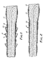
- FIG. 1 illustrates a termination assembly, generally indicated as 10, according to one embodiment of the present invention.
- the assembly 10 is a pre-stretched tubular sleeve 12 supported in the stretched condition by an easily removeable core 14.
- the assembly 10 is typically designated a "PST", which stands for pre-stretched tube.
- PST pre-stretched tube.
- the core 14 is a one-piece rigid spiral core having interconnected adjacent coils in a closed helical configuration, as described in U.S. patent no. 3,515,798.
- the outer sleeve 12 is preferably silicone rubber, although a wide variety of materials may be used so long as they possess the required arc and track resistance, ultraviolet resistance and ability to stretch and recover substantially their original dimensions when the core 14 is removed.
- the termination assembly of Figure 1 is primarily intended for outdoor use and so includes rain sheds 16 which increase the tracking length along the length of the sleeve 12. Space is usually more critical in indoor applications, so the rains sheds 16 are usually dispensed with in these situations, as shown in Figure 2.
- Either termination assembly 10 is applied as shown in Figure 3 to an electrical power cable 22 which has a suitable terminating device such as the lug 24 shown crimped to the conductor 26 of the cable 22.
- the cable 22 must be prepared by removing a predetermined length of insulation 28 covering the conductor 26 and a greater predetermined length of semi-conductive shielding 30 covering the insulation 28. Cutting back the shield 30 causes a discontinuity in the electrical field surrounding the conductor 26 which results in high electrical stresses an the end of the shield 30. The high stress can cause electrical discharge to occur, which in turn may cause breakdown of the insulation 28 of the cable 22 or the termination sleeve 12.
- the present invention is intended to control these high electrical stresses to avoid these undesirable results.
- Electrical stress control is provided in the termination 10 by the combined use of a high permittivity stress control tube 18 lining a portion of the sleeve 12, and a conformable stress control material 20 within the stress control tube 18.
- the thicknesses of the stress control tube 18 and the conformable stress control material 20, the length of the conformable stress control material 20 and the permittivity of both the stress control tube 18 and the conformable stress control material 20 are controlled to accomplish the desired stress control within the termination assembly 10.
- the high permittivity stress control tube 18 is described generally in U.S. patent number 4,363,842, which is incorporated herein by reference.
- the article taught in that patent has been modified somewhat to produce the preferred stress control tube 18 defined by the following composition: Parts by Weight Nordel 1470 (Tradename for an ethylene/propylene/diene monomer rubber commercially available from Dupont) 50 Nordel 1440 (Tradename for an ethylene/propylene/diene monomer rubber commercially available from Dupont) 50 Zinc oxide (French Process) 5.0 ARO60 Carbon Black (a N754 grade, large particle size carbon black commercially available from J.M.
- the conformable stress control material 20 is described in U.S. patent application 08/524,390 filed on like date as the present application and identified as attorney docket number 51948USA5A.
- the conformable stress control material 20 is comprised of a resin component which consists of a blend of two polymeric resins; epihalohydrin polymers and insulating polymers having an electrical dissipation factor (tan ⁇ ) of less than 1.
- Epihalohydrin polymers suitable for use are the elastomeric polymers of an epihalohydrin in homopolymer or copolymer form. Such polymers are prepared by polymerization of the monomeric material in mass or in solution with organometallic catalysts, and may be homopolymers, copolymers, terpolymers, etc.
- homopolymers examples include epichlorohydrin, or epibromohydrin; useful copolymers include copolymers of epihalohydrins with alkylene oxides, and copolymers with epoxides, e.g., propylene oxide, ethylene oxide, butene oxide, and epoxy ethers such as ethylglycidyl ether, allylglycidyl ether and the like. Such polymers are available from Zeon Chemicals, Inc.
- Preferred epihalohydrin polymers include copolymers with alkylene oxides, particularly ethylene and propylene oxides.
- the resin component also contains an insulating polymer having a tan ⁇ of less than one.
- Useful polymers include silicone, EPM or EPDM and hydrocarbon rubbers.
- Useful silicones include silicones which are fluid at room temperature and gum silicones; gum silicones are preferred for easy compounding and processability; most preferred are those gum silicones having a durometer of about 30.
- silicone elastomers include those fluid silicones available as Dow Corning DC 10,000, and the like, and gum silicones available as Elastosil® R300/30 from Wacker Silicones Corporation, and Silastic® GP31 from Dow Corning, and the like.
- This formulation produces a non-tacky, conformable stress control material 20 comprising:
- Preferred non-tacky electrical stress control materials comprise:
- the highest electrical stress of a prepared cable 22 occurs at the cut back end of the semi-conductive insulation shield 30.
- the present invention coordinates two components held to specific relative geometries based on their permittivities to provide stress control.
- the inner conformable stress control material 20 is positioned to extend in both directions from the cut edge of the shield 30 and should have a thickness sufficient to fill the radial step from the outer surface of the cable insulation 28 to the outer surface of the shield 30.
- the stress control tube 18 covers the conformable stress control material 20 and extends beyond the conformable stress control material 20 in both directions from the edge of the shield 30.
- the maximum internal electrical stress at the cable insulation 28 is primarily affected by the permittivity of the conformable stress control material 30.
- the permittivity of the conformable stress control material must be high enough to prevent its breakdown at the maximum power frequency voltage withstand required for the cable and its attached termination to achieve the required voltage rating in accordance with industry standard tests.
- the breakdown strengths for the conformable stress control materials tested were about 11800 V/mm.
- the permittivity of the comformable stress control material should be at least about 16. Since the most common voltage range is 15 to 69 kV, the preferred value for the permittivity is greater than 22, and most preferably is greater than 25.
- This relationship assumes a thickness of the termination sleeve 12 of about 2 mm. This thickness being the thinnest which will withstand voltage breakdown through the sleeve 12 to conserve material. Increased thickness of the sleeve 12 will also reduce stress at the outer surface of the sleeve 12.
- the maximum permissible external stresses, S, must be below a level which would cause electrical breakdown of air during impulse conditions.
- the impulse breakdown strength for terminations was found to be between about 3000 and 9200 Volts/mm.
- the preferred embodiment should maintain stress at required impulse levels at about 3150 Volts/mm. This factor allows a maximum quantity for B to be calculated.
- the thickness of the conformable stress control material 20 be at least 1 mm and most preferably between 2 and 3 mm to ensure that the material 20 completely fills the step at the cut end of the shield 30.
- the length of the conformable material 20 is at least 10 mm and preferably 25 to 50 mm along the cable insulation 28, in addition it is preferred that the conformable material extend about 10 mm on top of the cable shield 30 to ensure intimate contact with the shield 30, although this extension is not necessary so long as there is contact between the conformable stress control material 20 and the cable shield 30.
- the stress control tube 18 is preferably about 60 mm long, it being found that a longer length has no further effect for tube 18 permittivities of less than 50.
- the tube 18 should not extend beyond the cut end of the cable insulation 28 and should not extend beyond the cut-back point of any further layers (for example, any metal shielding) above the cable shield 30.
- the thickness of the tube 18 is preferably at least 1 mm and most preferably between 2 and 3 mm.
- Manipulation of these various parameters permits one to predict, for example, the necessary permittivity of the stress control tube 18 to be determined based on dimensions given or allows one to predict the dimensions the two stress control components must assume for given permittivities of the materials.
Landscapes
- Insulating Bodies (AREA)
- Cable Accessories (AREA)
- Details Of Indoor Wiring (AREA)
Claims (1)
- Abschluß eines elektrischen Stromkabels mit einem inneren Leiter (26), einer den Leiter (26) umgebenden elektrischen Isolierung (28) und einer die Isolierung umgebenden halbleitfähigen Abschirmung (30), wobei die Abschirmung (30) auf eine vorbestimmte Länge entfernt ist und die Isolierung (28) auf eine geringere vorbestimmte Länge entfernt ist, um den Leiter (26) freizulegen, wobei der Abschluß aufweist:dadurch gekennzeichnet, daßeine Schicht aus konformem Feldsteuermaterial (20) mit relativ hoher absoluter Dielektrizitätskonstante, die in Kontakt mit dem Ende der Kabelabschirmung (30) angeordnet ist und sich entlang der Kabelisolierung (28) erstreckt;ein über dem konformen Feldsteuermaterial (20) angeordnetes polymeres Feldsteuerrohr (18); undeine über dem Feldsteuerrohr (18) angeordnete polymere elektrisch isolierende Schicht (12);
die absolute Dielektrizitätskonstante εp des konformen Feldsteuermaterials (20) wenigstens ungefähr den Wert 16 hat, und wobei die Länge Lp des konformen Feldsteuermaterials (20) über der Kabelisolierung (28), die Dicke tp des konformen Feldsteuermaterials (20) und die Dicke tt des Feldsteuerrohres (18) durch die folgende Gleichung definiert sind, wobei B kleiner als ungefähr 0,56 ist:εp die absolute Dielektrizitätskonstante des konformen Feldsteuermaterials ist;εt die absolute Dielektrizitätskonstante des Feldsteuerrohres angibt;lp die Länge des konformen Feldsteuermaterials über der Kabelisolierung in Millimetern angibt;tt die Dicke des Feldsteuerrohres in Millimetern bezeichnet; undtp die Dicke des konformen Feldsteuermaterials in Millimetern angibt.
Applications Claiming Priority (3)
| Application Number | Priority Date | Filing Date | Title |
|---|---|---|---|
| US52423695A | 1995-09-06 | 1995-09-06 | |
| US524236 | 1995-09-06 | ||
| PCT/US1996/012478 WO1997009763A1 (en) | 1995-09-06 | 1996-07-30 | Stress control for termination of a high voltage cable |
Publications (2)
| Publication Number | Publication Date |
|---|---|
| EP0848865A1 EP0848865A1 (de) | 1998-06-24 |
| EP0848865B1 true EP0848865B1 (de) | 1999-03-03 |
Family
ID=24088355
Family Applications (1)
| Application Number | Title | Priority Date | Filing Date |
|---|---|---|---|
| EP96926809A Expired - Lifetime EP0848865B1 (de) | 1995-09-06 | 1996-07-30 | Feldsteuerung für hochspannungskabelendverschluss |
Country Status (7)
| Country | Link |
|---|---|
| EP (1) | EP0848865B1 (de) |
| JP (1) | JP4205164B2 (de) |
| AU (1) | AU6683696A (de) |
| BR (1) | BR9610112A (de) |
| DE (1) | DE69601649T2 (de) |
| ES (1) | ES2128181T3 (de) |
| WO (1) | WO1997009763A1 (de) |
Families Citing this family (6)
| Publication number | Priority date | Publication date | Assignee | Title |
|---|---|---|---|---|
| US6015629A (en) * | 1995-09-06 | 2000-01-18 | 3M Innovative Properties Company | Stress control for termination of a high voltage cable |
| FR2753844B1 (fr) * | 1996-09-26 | 1998-10-30 | Equipement pour extremite de cable et materiau de constitution de l'equipement | |
| FR2766981B1 (fr) * | 1997-07-29 | 1999-09-10 | Telecommunications Sa | Manchon de protection a couche conductrice interne pour une extremite de cable |
| FR2766982B1 (fr) * | 1997-07-29 | 1999-09-10 | Telecommunications Sa | Manchon de protection muni d'un embout conducteur pour une extremite de cable |
| CN103715647A (zh) | 2012-10-09 | 2014-04-09 | 泰科电子(上海)有限公司 | 用于电力电缆的冷缩式终端 |
| JP6357681B2 (ja) * | 2014-06-02 | 2018-07-18 | 住電機器システム株式会社 | インナーコアリボン、インナーコアおよびインナーコアの製造方法 |
Family Cites Families (4)
| Publication number | Priority date | Publication date | Assignee | Title |
|---|---|---|---|---|
| US4363842A (en) * | 1981-03-02 | 1982-12-14 | Minnesota Mining And Manufacturing Company | Elastomeric pre-stretched tubes for providing electrical stress control |
| FR2518837B1 (fr) * | 1981-12-18 | 1985-08-09 | Fabrication Cables Elect Cie G | Procede de preparation d'extremites de cables electriques a champ radial haute tension et cables electriques ainsi obtenus |
| GB8303462D0 (en) * | 1983-02-08 | 1983-03-16 | Raychem Gmbh | Electrical stress control |
| US4551915A (en) * | 1983-04-06 | 1985-11-12 | Raychem Corporation | Method for terminating a high voltage cable |
-
1996
- 1996-07-30 AU AU66836/96A patent/AU6683696A/en not_active Abandoned
- 1996-07-30 EP EP96926809A patent/EP0848865B1/de not_active Expired - Lifetime
- 1996-07-30 WO PCT/US1996/012478 patent/WO1997009763A1/en not_active Ceased
- 1996-07-30 ES ES96926809T patent/ES2128181T3/es not_active Expired - Lifetime
- 1996-07-30 BR BR9610112A patent/BR9610112A/pt not_active IP Right Cessation
- 1996-07-30 DE DE69601649T patent/DE69601649T2/de not_active Expired - Lifetime
- 1996-07-30 JP JP51118797A patent/JP4205164B2/ja not_active Expired - Fee Related
Also Published As
| Publication number | Publication date |
|---|---|
| BR9610112A (pt) | 1999-02-23 |
| WO1997009763A1 (en) | 1997-03-13 |
| JPH11512595A (ja) | 1999-10-26 |
| DE69601649T2 (de) | 1999-10-28 |
| JP4205164B2 (ja) | 2009-01-07 |
| ES2128181T3 (es) | 1999-05-01 |
| DE69601649D1 (de) | 1999-04-08 |
| EP0848865A1 (de) | 1998-06-24 |
| AU6683696A (en) | 1997-03-27 |
Similar Documents
| Publication | Publication Date | Title |
|---|---|---|
| US6340794B1 (en) | Stress control for termination of a high voltage cable | |
| US6015629A (en) | Stress control for termination of a high voltage cable | |
| EP0848854B1 (de) | Epihalohydrinwerkstoff zur verminderung elektrischer beanspruchung | |
| EP0148196B2 (de) | Gerät zur verminderung der beanspruchung eines dielektrikums und verfahren | |
| EP0847610B1 (de) | Elastisch rückstellbare silikonspleissumhüllung | |
| EP0780949B1 (de) | Universeller Kabeladapter, mit Hilfe des Adapters hergestellte Kabelverbindung sowie Verfahren zur Herstellung derselben | |
| EP0121986B1 (de) | Vorrichtung und Verfahren zur Verminderung elektrischer Beanspruchung | |
| EP1010226A1 (de) | Kabelendverschluss | |
| WO1997009763A1 (en) | Stress control for termination of a high voltage cable | |
| CA2231233C (en) | Stress control for termination of a high voltage cable | |
| US4319073A (en) | Push-on end termination for shielded power cable conductors of sector-shaped conductor cross section | |
| JP3029203B2 (ja) | 架橋ポリエチレン電力ケーブルの接続部及び端末部 | |
| EP0522760A1 (de) | Wärmerückstellbarer, röhrenförmiger, spannungsregelnder Bauteil | |
| CN216451143U (zh) | 电缆终端组件及电缆终端装置 | |
| EP4586423A1 (de) | Zubehör für hvdc-kabel auf basis von thermoplastischen elastomeren | |
| TW202606138A (zh) | 電力纜線用終端連接部 | |
| JP3083098B2 (ja) | 架橋ポリエチレン電力ケーブルの接続部及び端末部 | |
| JPH084633Y2 (ja) | 直流耐電圧試験用リードケーブル終端部 | |
| JPH06269119A (ja) | ゴム製ストレスコーン | |
| JP4253404B2 (ja) | 高電圧機器用絶縁物 | |
| JPH11283443A (ja) | 絶縁物 | |
| JPS6123734B2 (de) |
Legal Events
| Date | Code | Title | Description |
|---|---|---|---|
| PUAI | Public reference made under article 153(3) epc to a published international application that has entered the european phase |
Free format text: ORIGINAL CODE: 0009012 |
|
| 17P | Request for examination filed |
Effective date: 19980218 |
|
| AK | Designated contracting states |
Kind code of ref document: A1 Designated state(s): DE ES FR GB IT |
|
| GRAG | Despatch of communication of intention to grant |
Free format text: ORIGINAL CODE: EPIDOS AGRA |
|
| GRAG | Despatch of communication of intention to grant |
Free format text: ORIGINAL CODE: EPIDOS AGRA |
|
| GRAH | Despatch of communication of intention to grant a patent |
Free format text: ORIGINAL CODE: EPIDOS IGRA |
|
| 17Q | First examination report despatched |
Effective date: 19980708 |
|
| GRAH | Despatch of communication of intention to grant a patent |
Free format text: ORIGINAL CODE: EPIDOS IGRA |
|
| GRAA | (expected) grant |
Free format text: ORIGINAL CODE: 0009210 |
|
| AK | Designated contracting states |
Kind code of ref document: B1 Designated state(s): DE ES FR GB IT |
|
| REF | Corresponds to: |
Ref document number: 69601649 Country of ref document: DE Date of ref document: 19990408 |
|
| ET | Fr: translation filed | ||
| REG | Reference to a national code |
Ref country code: ES Ref legal event code: FG2A Ref document number: 2128181 Country of ref document: ES Kind code of ref document: T3 |
|
| ITF | It: translation for a ep patent filed | ||
| PLBE | No opposition filed within time limit |
Free format text: ORIGINAL CODE: 0009261 |
|
| STAA | Information on the status of an ep patent application or granted ep patent |
Free format text: STATUS: NO OPPOSITION FILED WITHIN TIME LIMIT |
|
| 26N | No opposition filed | ||
| REG | Reference to a national code |
Ref country code: GB Ref legal event code: IF02 |
|
| REG | Reference to a national code |
Ref country code: HK Ref legal event code: WD Ref document number: 1014344 Country of ref document: HK |
|
| REG | Reference to a national code |
Ref country code: FR Ref legal event code: PLFP Year of fee payment: 20 |
|
| PGFP | Annual fee paid to national office [announced via postgrant information from national office to epo] |
Ref country code: ES Payment date: 20150611 Year of fee payment: 20 |
|
| PGFP | Annual fee paid to national office [announced via postgrant information from national office to epo] |
Ref country code: GB Payment date: 20150729 Year of fee payment: 20 Ref country code: DE Payment date: 20150722 Year of fee payment: 20 |
|
| PGFP | Annual fee paid to national office [announced via postgrant information from national office to epo] |
Ref country code: FR Payment date: 20150629 Year of fee payment: 20 |
|
| PGFP | Annual fee paid to national office [announced via postgrant information from national office to epo] |
Ref country code: IT Payment date: 20150727 Year of fee payment: 20 |
|
| REG | Reference to a national code |
Ref country code: DE Ref legal event code: R071 Ref document number: 69601649 Country of ref document: DE |
|
| REG | Reference to a national code |
Ref country code: GB Ref legal event code: PE20 Expiry date: 20160729 |
|
| PG25 | Lapsed in a contracting state [announced via postgrant information from national office to epo] |
Ref country code: GB Free format text: LAPSE BECAUSE OF EXPIRATION OF PROTECTION Effective date: 20160729 |
|
| REG | Reference to a national code |
Ref country code: ES Ref legal event code: FD2A Effective date: 20161107 |
|
| PG25 | Lapsed in a contracting state [announced via postgrant information from national office to epo] |
Ref country code: ES Free format text: LAPSE BECAUSE OF EXPIRATION OF PROTECTION Effective date: 20160731 |