EP0848832B1 - Anordnung und verfahren zur bestimmung der position eines markers in einem organischen hohlraum - Google Patents
Anordnung und verfahren zur bestimmung der position eines markers in einem organischen hohlraum Download PDFInfo
- Publication number
- EP0848832B1 EP0848832B1 EP96931761A EP96931761A EP0848832B1 EP 0848832 B1 EP0848832 B1 EP 0848832B1 EP 96931761 A EP96931761 A EP 96931761A EP 96931761 A EP96931761 A EP 96931761A EP 0848832 B1 EP0848832 B1 EP 0848832B1
- Authority
- EP
- European Patent Office
- Prior art keywords
- magnetic field
- marker
- coil
- arrangement
- sensors
- Prior art date
- Legal status (The legal status is an assumption and is not a legal conclusion. Google has not performed a legal analysis and makes no representation as to the accuracy of the status listed.)
- Expired - Lifetime
Links
- 239000003550 marker Substances 0.000 title claims description 69
- 238000000034 method Methods 0.000 title claims description 14
- 238000005259 measurement Methods 0.000 claims description 14
- 238000001514 detection method Methods 0.000 claims description 4
- 239000000696 magnetic material Substances 0.000 claims description 3
- 230000001960 triggered effect Effects 0.000 claims description 2
- SZVJSHCCFOBDDC-UHFFFAOYSA-N ferrosoferric oxide Chemical compound O=[Fe]O[Fe]O[Fe]=O SZVJSHCCFOBDDC-UHFFFAOYSA-N 0.000 claims 2
- 230000005389 magnetism Effects 0.000 claims 2
- 230000015572 biosynthetic process Effects 0.000 claims 1
- 230000001747 exhibiting effect Effects 0.000 claims 1
- 229910006297 γ-Fe2O3 Inorganic materials 0.000 claims 1
- 210000001035 gastrointestinal tract Anatomy 0.000 description 10
- 238000011156 evaluation Methods 0.000 description 4
- 210000000936 intestine Anatomy 0.000 description 3
- 238000002595 magnetic resonance imaging Methods 0.000 description 3
- 229910001566 austenite Inorganic materials 0.000 description 2
- 230000007423 decrease Effects 0.000 description 2
- 238000003745 diagnosis Methods 0.000 description 2
- 208000010643 digestive system disease Diseases 0.000 description 2
- 238000006073 displacement reaction Methods 0.000 description 2
- 230000001939 inductive effect Effects 0.000 description 2
- 230000005415 magnetization Effects 0.000 description 2
- 239000002184 metal Substances 0.000 description 2
- 238000012935 Averaging Methods 0.000 description 1
- 208000018522 Gastrointestinal disease Diseases 0.000 description 1
- 208000022559 Inflammatory bowel disease Diseases 0.000 description 1
- 210000000683 abdominal cavity Anatomy 0.000 description 1
- 239000002775 capsule Substances 0.000 description 1
- 239000012876 carrier material Substances 0.000 description 1
- 210000001072 colon Anatomy 0.000 description 1
- 238000002405 diagnostic procedure Methods 0.000 description 1
- 238000012631 diagnostic technique Methods 0.000 description 1
- 238000010586 diagram Methods 0.000 description 1
- 201000010099 disease Diseases 0.000 description 1
- 208000037265 diseases, disorders, signs and symptoms Diseases 0.000 description 1
- 230000000694 effects Effects 0.000 description 1
- 230000002496 gastric effect Effects 0.000 description 1
- 230000002452 interceptive effect Effects 0.000 description 1
- 239000007788 liquid Substances 0.000 description 1
- 239000000463 material Substances 0.000 description 1
- 239000002923 metal particle Substances 0.000 description 1
- 238000013508 migration Methods 0.000 description 1
- 230000005012 migration Effects 0.000 description 1
- 231100000252 nontoxic Toxicity 0.000 description 1
- 230000003000 nontoxic effect Effects 0.000 description 1
- 230000008855 peristalsis Effects 0.000 description 1
- 235000021395 porridge Nutrition 0.000 description 1
- 239000000700 radioactive tracer Substances 0.000 description 1
- 230000035945 sensitivity Effects 0.000 description 1
- 239000010802 sludge Substances 0.000 description 1
- 210000000813 small intestine Anatomy 0.000 description 1
- 239000007787 solid Substances 0.000 description 1
- 238000001228 spectrum Methods 0.000 description 1
- 210000002784 stomach Anatomy 0.000 description 1
- 230000002123 temporal effect Effects 0.000 description 1
- 238000002560 therapeutic procedure Methods 0.000 description 1
- 239000010409 thin film Substances 0.000 description 1
- 238000002604 ultrasonography Methods 0.000 description 1
Images



Classifications
-
- A—HUMAN NECESSITIES
- A61—MEDICAL OR VETERINARY SCIENCE; HYGIENE
- A61B—DIAGNOSIS; SURGERY; IDENTIFICATION
- A61B5/00—Measuring for diagnostic purposes; Identification of persons
- A61B5/06—Devices, other than using radiation, for detecting or locating foreign bodies ; Determining position of diagnostic devices within or on the body of the patient
-
- A—HUMAN NECESSITIES
- A61—MEDICAL OR VETERINARY SCIENCE; HYGIENE
- A61B—DIAGNOSIS; SURGERY; IDENTIFICATION
- A61B5/00—Measuring for diagnostic purposes; Identification of persons
- A61B5/06—Devices, other than using radiation, for detecting or locating foreign bodies ; Determining position of diagnostic devices within or on the body of the patient
- A61B5/061—Determining position of a probe within the body employing means separate from the probe, e.g. sensing internal probe position employing impedance electrodes on the surface of the body
- A61B5/062—Determining position of a probe within the body employing means separate from the probe, e.g. sensing internal probe position employing impedance electrodes on the surface of the body using magnetic field
-
- A—HUMAN NECESSITIES
- A61—MEDICAL OR VETERINARY SCIENCE; HYGIENE
- A61B—DIAGNOSIS; SURGERY; IDENTIFICATION
- A61B5/00—Measuring for diagnostic purposes; Identification of persons
- A61B5/07—Endoradiosondes
- A61B5/073—Intestinal transmitters
-
- G—PHYSICS
- G01—MEASURING; TESTING
- G01V—GEOPHYSICS; GRAVITATIONAL MEASUREMENTS; DETECTING MASSES OR OBJECTS; TAGS
- G01V3/00—Electric or magnetic prospecting or detecting; Measuring magnetic field characteristics of the earth, e.g. declination, deviation
- G01V3/08—Electric or magnetic prospecting or detecting; Measuring magnetic field characteristics of the earth, e.g. declination, deviation operating with magnetic or electric fields produced or modified by objects or geological structures or by detecting devices
Definitions
- the invention relates to an arrangement and a method for determination the position of a marker in an organic cavity, in particular to determine the local passage speeds of a marker the gastrointestinal tract, especially in the small intestine.
- the Invention takes place in the context of medical diagnosis of the gastrointestinal tract Application without a diagnostic procedure as such affect.
- Medical examinations are known in which a repeated determination of the local passage speed of a marker through the gastrointestinal tract is required. This is the case, for example, with inflammatory bowel diseases such as Chron's disease, functional gastrointestinal disorders and physiological examinations of the gastrointestinal tract.
- the usual diagnostic technique such as X-ray using contrast sludge, must not be used in such cases because of the radiation exposure. The same applies to scintigraphic methods.
- Magnetic resonance imaging or magnetic resonance is a complex process and expensive procedure that is used for frequently repeated examinations not suitable and for determining a local passage speed, which is a time interval between successive position determinations of markers of the order of 10 s, is too slow [K. Fitzgerald, IEEE Spectrum 27 (1990) p. 52].
- the position of metal particles can be determined with metal detectors become.
- the lateral accuracy in determining the position decreases however with the distance from the body surface and becomes at one Distance of> 10 cm worse than 1 cm [K. Ewe, therapy week 41 (1991), p. 77].
- the accuracy of a depth measurement is described in this Work reported nothing. However, since they are generally worse than that is lateral accuracy, this method is sufficient for measuring the local passage speed is not sufficient.
- the invention has for its object an arrangement and a Method for determining the position of markers in an organic Cavity, particularly in the entire gastrointestinal tract to indicate the an accuracy of positioning better than 1 cm in all guaranteed three coordinate directions and times for each Position determination of 10 s and below enabled.
- the through the measured values obtained according to the invention for the respective Marker position should also provide a spatial representation be deliverable.
- a magnetizable marker which can be solitary or in a viscous carrier solution or in connection with a solid carrier material (capsule), consists of a spherically symmetrically distributed, isotropic, semi-hard magnetic material which has a medium-sized coercive force, preferably in the range from 10 4 to 10 5 A / m and has a large relative remanence, preferably> 0.8, application.
- the marker preferably consists essentially of ⁇ -Fe 2 O 3 and / or Fe 3 O 4 , which, in addition to the required magnetic properties, is also non-toxic.
- Such a marker is introduced into the organic cavity and exposed to a primary magnetic field of an electrical coil which is subjected to a pulsed current.
- the coil diameter should be so large that it is at least 5 times the marker diameter.
- the coil is designed in such a way that it can generate a rotationally symmetrical, almost homogeneous primary magnetic field in a region of the size of approximately 10 ⁇ 10 ⁇ 30 cm 3 . Due to the pulsed current application of the coil, the marker is magnetized repeatedly during its migration through the organic cavity in short time intervals, whereby the magnetic moment of the marker adjusts itself parallel to the primary magnetic field of the coil, so that rotational movements of the marker, as a possibly distorting measurement variable, no longer matter.
- the primary magnetic field of the coil has decayed to values of preferably less than 10% of the maximum value
- at least one measurement of the secondary magnetic field of the marker is carried out by means of anisotropic magnetic field sensors.
- the time interval between the primary magnetic field maxima can be adapted to the gastrointestinal tract areas to be examined and is in any case so short that interfering translational or rotational movements of the marker do not take place or can be compensated for by averaging several measurements; this time interval is preferably set to ⁇ 10 s.
- the primary magnetic field is preferably generated by a pair of coaxial coils, between which the patient's body with the area to be examined is arranged.
- the distance of the coil should be adapted to the patient's body and is preferably between 30 cm and 40 cm.
- the direction of the primary magnetic field is parallel to the common axis of both coils and is preferably reversed between two successive magnetizations.
- the maximum value H p of the primary magnetic field is chosen so that a sufficiently high remanence of the marker is generated. With the selected marker material, it is advantageous to generate an H p of> 10 3 A / m.
- the upper limit of H p is limited solely by the technical effort and can be up to 10 5 A / m, for example in the case of pulse fields.
- H ⁇ S H S cos ( ⁇ + ⁇ )
- H ⁇ S H S sin ( ⁇ + ⁇ )
- suitable magnetic field sensors preferably anisotropic, magnetoresistive thin-film sensors, as are currently available.
- the amount of H ⁇ / S therefore has a maximum, while at the same time H ⁇ / S is zero.
- a magnetic field sensor for H ⁇ / S arranged on this coil axis only shows a possible interference field. If the marker deviates from the coil axis, the magnetic field sensor delivers an additional signal, the sign of which changes with the polarity of the marker remanence, that is, with the polarity of the primary magnetic field. This frequency-selectively amplifiable signal from this magnetic field sensor therefore indicates whether the marker is on the coil axis.
- the signal can therefore be adjusted to zero, which is why, according to the invention, the coil axis is tracked into the marker center.
- a second magnetic field sensor which is symmetrically arranged and fixed on the coil axis, for determining H Betician / S can be arranged, the signal of which is added with the opposite sign to the signal of the first magnetic field sensor.
- several such magnetic field sensors can be arranged radially distributed axially symmetrically around the coil axis and electrically connected in the above sense.
- H S is the same size at the location of these two magnetic field sensors. If both sensors have the same sensitivity, the difference between these signals is zero.
- the difference signal is a monotonic function of z and, if m is known, a measure of the deviation of the marker in the z direction.
- the value of m can be determined in a separate measuring step before and / or after the marker has been administered to the patient. Analogous to the determination in the radial direction, the accuracy of the measurement in the z direction can be increased by further H ⁇ / S magnetic field sensors arranged on the coil axis and electrically connected accordingly.
- the current position of the marker within the organic is thus closed on the one hand by the position of the coil axis the registration of which means are provided after the Zero adjustment of the H ⁇ / S signal using suitable shifting means and secondly, completely determined by the size of the H ⁇ / S signal.
- reference markers become in the form of small coils or magnets on which Patient's body attached to defined locations, their position also is measured.
- the determination of the local passage speed of the marker is easily obtained as a quotient from the respective distance two measuring points between two current impulses Coil (s) and the time difference between these adjacent points.
- a patient 1 whose gastrointestinal tract is to be examined, lies on a non-metallic support 2.
- Two identical coils 3 and 4 are with their coil axes on a common axis XX with a clear width A of the order of 30 cm spaced apart. 3, the coils 3, 4 are acted upon by pulse-shaped currents.
- a maximum primary magnetic field for example with a strength of 20,000 A / m, is generated in the geometric center 5, depending on the selected current pulse frequency, for example, at a time interval of 1 s.
- a marker 6 consisting of ⁇ -Fe 2 O 3 , the diameter of which is approximately 8 mm, was administered orally to patient 1. After each magnetization in the named primary magnetic field, the marker 6 has a remanent magnetic moment m of approx. 7 ⁇ 10 -5 Am 2 .
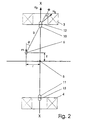
- FIG. 2 shows schematically how the coils 3, 4 are each rigidly connected to anisotropic magnetoresistive magnetic field sensors 10, 11, 12, 13.
- the magnetic field sensors 10, 11 are designed in such a way that they serve the exclusive detection of a component of the secondary magnetic field originating from the marker and the magnetic field sensors 12, 13 of a secondary magnetic field called perpendicular to it. If the marker 6 is located in the center of the common coil axis XX, the magnetic field component H ⁇ / S, in accordance with the above provisions, is approximately 4 ⁇ 10 ⁇ 2 A / m at the location of the magnetic field sensors 10, 11, while the magnetic field component H ⁇ running perpendicular thereto / S is zero.
- FIG. 1 shows schematically how the coils 3, 4 are each rigidly connected to anisotropic magnetoresistive magnetic field sensors 10, 11, 12, 13.
- the magnetic field sensors 10, 11 are designed in such a way that they serve the exclusive detection of a component of the secondary magnetic field originating from the marker and the magnetic field sensors 12, 13 of a secondary
- the radial component of the secondary magnetic field at the location of the radial sensors 12, 13 is approximately 4 ⁇ 10 -3 A / m.
- the axial component of the secondary magnetic field at the location of the sensor 10 is approximately 5.2 ⁇ 10 -2 A / m, whereas it is only approximately 3.5 at the location of the sensor 11 ⁇ 10 -2 A / m.
- Anisotropic magnetic field sensors can deliver signal voltages of 10 -4 V at a field strength of 1 A / m.
- the coil axis XX common in the example is now shifted according to the invention with the aid of means for relative tracking, which can be most simply in the form of a cross table 80 (cf. FIG. 1) connected to the coils 3 and 4, as long as until this signal disappears. If this is the case, the coil axis is again in the marker center.
- the position assumed in this regard is detected by a location sensor 8 indicated in FIG. 3 and fed to a storage and evaluation unit 9.
- the difference of 1.7 ⁇ V can also be amplified to about 170 ⁇ V with the frequency-selective amplifier 7.
- These signals assigned to the respective vertical marker position are also fed to the storage and evaluation unit 9.
- the required number of measured values is available for each current marker position, which clearly describes its current spatial position in the gastrointestinal tract.
- the marker positions obtained one after the other in the described manner form a point chain which represents the path of the marker.
- the quotient from the distance between adjacent points and the time interval between these points is a measure of the local passage speed of the marker 6 to be determined. All the measurement data obtained can be obtained after appropriate evaluation and calibration during or after the examination of the marker movement in the patient display a monitor 15 three-dimensionally.
- the patient is not one Exposed to radiation exposure and the measurement can be taken as often as required be repeated.
- the earth's magnetic field or the local local interference field is none Has no effect on the measurement result sought and so none complex shielding measures are required.
Landscapes
- Life Sciences & Earth Sciences (AREA)
- Health & Medical Sciences (AREA)
- Engineering & Computer Science (AREA)
- Physics & Mathematics (AREA)
- Surgery (AREA)
- General Health & Medical Sciences (AREA)
- Veterinary Medicine (AREA)
- Public Health (AREA)
- Animal Behavior & Ethology (AREA)
- Molecular Biology (AREA)
- Medical Informatics (AREA)
- Heart & Thoracic Surgery (AREA)
- Biophysics (AREA)
- Pathology (AREA)
- Biomedical Technology (AREA)
- Remote Sensing (AREA)
- Human Computer Interaction (AREA)
- Geophysics (AREA)
- Electromagnetism (AREA)
- General Physics & Mathematics (AREA)
- Environmental & Geological Engineering (AREA)
- General Life Sciences & Earth Sciences (AREA)
- Geology (AREA)
- Measurement Of Length, Angles, Or The Like Using Electric Or Magnetic Means (AREA)
- Measurement And Recording Of Electrical Phenomena And Electrical Characteristics Of The Living Body (AREA)
Description
Die übliche Diagnose-Technik, wie Röntgen unter Verwendung von Kontrastbrei, darf in solchen Fällen wegen der Strahlenbelastung nicht angewendet werden. Dasselbe gilt für szintigraphische Methoden.
Bevorzugt wird das Primärmagnetfeld im Rahmen der Erfindung durch ein Paar koaxialer Spulen erzeugt, zwischen denen der Patientenkörper mit dem zu untersuchenden Bereich angeordnet wird. Der Abstand der Spule soll dem Patientenkörper angepaßt sein und beträgt vorzugsweise zwischen 30 cm und 40 cm. Die Richtung des Primärmagnetfeldes ist parallel zur gemeinsamen Achse beider Spulen und wird vorzugsweise zwischen zwei aufeinander folgenden Aufinagnetisierungen umgepolt. Der Maximalwert Hp des Primärmagnetfeldes wird so gewählt, daß eine hinreichend hohe Remanenz des Markers erzeugt wird. Es ist beim gewählten Markermaterial vorteilhaft, ein Hp von > 103 A/m zu erzeugen. Nach oben ist Hp allein durch den technischen Aufwand begrenzt und kann, z.B. bei Impulsfeldem, bis 105 A/m betragen.
Die Komponenten des Sekundärmagnetfeldes parallel H ∥ / S und senkrecht H ⊥ / S zur Remanenzrichtung werden durch die Gleichungen
Sobald der Marker sich auf der Spulenachse befindet (ϑ = Φ = 0), ist bei vorgegebenem Wert des magnetischen Moments m der Betrag von HS gemäß Gleichung (1) eine eindeutige Funktion von R. Im Spezialfall, unter Verwendung zweier koaxial zueinander angeordneter gleicher Spulen und der Position des Marker genau in der Mitte zwischen diesen Spulen und dem Einsatz je eines zur jeweiligen Spule und zur gemeinsamen Spulenachse gleich positionierten H ∥ / S-Magnetfeldsensors, ist HS am Ort dieser beiden Magnetfeldsensoren gleich groß. Falls beide Sensoren die gleiche Empfindlichkeit besitzen, ist die Differenz dieser Signale Null. Weicht die Markerposition auf der Spulenachse um einen Abstand z von genannter Mittenstellung ab, dann ist das Differenzsignal eine monotone Funktion von z und, bei bekanntem m, ein Maß für die Abweichung des Markers in z-Richtung. Der Wert von m kann in einem gesonderten Meßschritt bestimmt werden, bevor und/oder nachdem der Marker dem Patienten verabreicht wird bzw. wurde. Die Genauigkeit der Messung in z-Richtung kann analog zur Bestimmung in radialer Richtung durch weitere auf der Spulenachse angeordnete und elektrisch entsprechend verschaltete H ∥ / S-Magnetfeldsensoren erhöht werden.
Anisotrope Magnetfeldsensoren können Signalspannungen von 10-4 V bei einer Feldstärke von 1 A/m liefern. Werden die Sensoren jeweils in den erfindungsgemäß vorgesehenen Pausen t1 (vgl. Fig. 4) zwischen zwei Primärfeldimpulsen mit dem zeitlichen Abstand t2 getriggert eingeschaltet, dann liefern die in Reihe geschalteten Radialsensoren 12, 13 nach einer radialen Markerverschiebung von r = 1 cm eine impulsförmige Wechselspannung mit einer Amplitude von 0,4 µV, die mit einem frequenzselektiven Verstärker 7 leicht auf 40 µV verstärkbar ist. Die im Beispiel gemeinsame Spulenachse X-X wird nun gemäß der Erfindung mit Hilfe von Mitteln zur relativen Nachführung, die am einfachsten in Form eines mit den Spulen 3 un 4 in Verbindung stehenden Kreuztisches 80 (vgl. Fig. 1) ausgebildet sein können, solange verschoben, bis dieses Signal verschwunden ist. Ist dies der Fall, befindet sich die Spulenachse wieder im Markerzentrum. Ihre diesbezüglich eingenommene Lage wird mit einem in Fig. 3 angedeuteten Ortssensor 8 erfaßt und einer Speicher- und Auswerteeinheit 9 zugeführt.
Nach einer Axialverschiebung des Markers 6 aus dem Zentrum 5 um z = 1 cm, im Beispiel nach oben, werden von den beiden Axialsensoren 10, 11 impulsförmige Wechselspannungen mit Amplituden von ca. 5,2 µV (am Sensor 10) bzw. ca. 3,5 µV (am Sensor 11) erzeugt. Die Differenz von 1,7 µV kann ebenfalls mit dem frequenzselektiven Verstärker 7 auf etwa 170 µV verstärkt werden. Diese der jeweiligen vertikalen Markerposition zugeordneten Signale werden ebenfalls der Speicher- und Auswerteeinheit 9 zugeführt. Somit steht für jede aktuelle Markerposition die erforderliche Anzahl von Meßwerten zur Verfügung, die seine aktuelle räumliche Lage im Magen-Darm-Trakt eindeutig beschreibt. Die auf die beschriebene Weise nacheinander gewonnenen Markerpositionen bilden eine Punktkette, die den Weg des Markers repräsentiert. Der Quotient aus dem Abstand benachbarter Punkte und dem Zeitintervall zwischen diesen Punkten steht dabei als Maß für die zu ermittelnde lokale Passage-Geschwindigkeit des Markers 6. All die gewonnenen Meßdaten lassen sich nach entsprechender Auswertung und Kalibrierung während oder nach der Untersuchung der Markerbewegung im Patienten auf einem Monitor 15 dreidimensional zur Anzeige bringen.
- 1 -
- Patient
- 2 -
- Auflage
- 3,4 -
- Spule
- 5 -
- geometrisches Zentrum
- 6 -
- Marker
- 7 -
- frequenzselektiver Verstärker
- 8 -
- Ortssensor
- 80 -
- Mittel zur Nachführung
- 9 -
- Speicher- und Auswerteeinheit
- 10, 11 -
- Axialsensoren
- 12, 13 -
- Radialsensoren
- 14 -
- Generator
- 15 -
- Monitor
- A -
- lichte Weite
- t1 -
- Meßintervall
- t2 -
- Intervall der Stromimpulsfolge
- X-X -
- Achse
- ϑ,Φ -
- Winkel
Claims (13)
- Anordnung zur Bestimmung der Position eines Markers in einem organischen Hohlraum, bei der ein magnetisierbarer Marker und Mittel zur Positionsbestimmung des Markers zum Einsatz gelangen, dadurch gekennzeichnet, daßvorgesehen sind.a) ein im organischen Hohlraum bewegbarer, magnetisierbarer Marker (6), bestehend aus einem halbharten Magnetmaterial mit einer großen relativen Remanenz und mittelgroßer Koerzitivfeldstärke,b) wenigstens eine elektrische Spule (3 oder 4), der ein Spulendurchmesser gegeben ist, der mindestens ein 5faches des Markerdurchmessers beträgt,c) Mittel (14) zur impulsförmigen Strombeaufschlagung genannter Spule,d) anisotrope Magnetfeldsensoren (10, 11; 12, 13), die axialsymmetrisch zur Spulenachse (X-X) genannter Spule (3 oder 4) und in einer starren geometrischen Verbindung zur Spule angeordnet sind,e) Mittel (80) zur Nachführung der Spulenachse in bezug auf die aktuelle Markerposition und Mittel (8) zur Positionsbestimmung der Spulenachse (X-X) undf) Mittel (7; 9) zur Signalerfassung, Speicherung und Auswertung der Signale der anisotropen Magnetfeldsensoren (10, 11; 12, 13) und der Mittel (8) zur Positionsbestimmung
- Anordnung gemäß Anspruch 1, dadurch gekennzeichnet, daß die wenigstens eine Spule (3 oder 4) so ausgebildet ist, daß sie ein rotationssymmetrisches, in einem Meßbereich in der Größenordnung von 10 · 10 · 30 cm3, nahezu homogenes magnetisches Primärfeld erzeugen läßt.
- Anordnung gemäß Anspruch 1 und 2, dadurch gekennzeichnet, daß bei Einsatz zweier Spulen (3, 4) diese zueinander koaxial und voneinander in einer lichten Weite (A) angeordnet sind, die die Aufnahme genannten organischen Hohlraums zuläßt.
- Anordnung gemäß Anspruch 1., dadurch gekennzeichnet, daß der Marker (6) kugelsymmetrisch ausgebildet ist und aus einem isotropen Magnetmaterial besteht, das eine Koerzitivfeldstärke im Bereich von 104 bis 105 A/m und eine relative Remanenz von vorzugsweise > 0,8 besitzt.
- Anordnung gemäß Anspruch 4, dadurch gekennzeichnet, daß der Marker im wesentlichen aus γ-Fe2O3 und/oder Fe3O4 gefertigt ist.
- Anordnung gemäß Anspruch 1, dadurch gekennzeichnet, daß für die anisotropen Magnetfeldsensoren (10, 11; 12, 13) magnetoresistive Dünnschichtsensoren gewählt sind.
- Anordnung gemäß Anspruch 1 und 6, dadurch gekennzeichnet, daß die anisotropen Magnetfeldsensoren so angeordnet sind, daßeingesetzt ist.wenigstens einer (10 oder 11) auf der Spulenachse zur Bestimmung der parallel zur Spulenachse (X-X) verlaufenden Magnetfeldkomponente des magnetischen Sekundärfeldes des Markers (6)und wenigstens einer (12 oder 13) zur Bestimmung einer senkrecht zur Spulenachse (X-X) verlaufenden radialen Magnetfeldkomponente des magnetischen Sekundärfeldes des Markers (6)
- Anordnung gemäß Anspruch 1 und 7, dadurch gekennzeichnet, daß bei Einsatz mehrerer anisotroper Magnetfeldsensoren zur Bestimmung der senkrecht zur Spulenachse verlaufenden radialen Magnetfeldkomponente des magnetischen Sekundärfeldes des Markers (6) diese axialsymmetrisch zur Spulenachse (X-X) und in einer senkrecht zur Spulenachse verlaufenden Ebene angeordnet sind.
- Anordnung gemäß Anspruch 1, 6, 7 oder 8, dadurch gekennzeichnet, daß die anisotropen Magnetfeldsensoren (10, 11; 12, 13) in einem Abstand zum Marker (6) angeordnet sind, der mindestens ein Dreifaches des Markerdurchmessers beträgt.
- Verfahren zur Bestimmung der Position eines Markers in einem organischen Hohlraum unter Verwendung einer Anordnung gemäß einem der vorstehenden Ansprüche, dadurch gekennzeichnet, daßa) die wenigstens eine Spule impulsförmig in einem zeitlichen Abstand mit im Vorzeichen jeweils wechselnden Strom beaufschlagt wird,b) zwischen zwei Stromimpulsen, wenn das durch sie erzeugte Primärmagnetfeld der Spule auf hinreichend kleine Werte abgeklungen ist, wenigstens einmal das von einem Marker stammende Sekundärmagnetfeld mittels anisotroper Magnetfeldsensoren parallel und senkrecht zur Spulenachse getrennt vermessen wird,c) die Spulenanordnung relativ zum Marker solange verschoben wird, bis die Magnetfeldsensoren, die der Bestimmung der radialen Sekundärmagnetfeldkomponente des Markers dienen, ein Nullsignal liefernd) und diese zugehörige Position der Spulenachse, als auch die zugehörigen Meßwerte, die die Magnetfeldsensoren, die der Erfassung der parallel zur Spulenachse verlaufenden Sekundärmagnetfeldkomponente des Markers dienen, abgespeichert und einer Anzeige zugeführt werden.
- Verfahren nach Anspruch 10, dadurch gekennzeichnet, daß die Signale der anisotropen Magnetfeldsensoren, welche durch das Sekundärmagnetfeld des Markers erzeugt werden, zu einem Zeitpunkt getriggert ausgelesen werden, wenn das durch die Spule erzeugte Primärmagnetfeld zwischen zwei Stromimpulsen auf weniger als 10% seines Maximalwertes abgeklungen ist.
- Verfahren nach Anspruch 10 oder 11, dadurch gekennzeichnet, daß zwischen zwei Stromimpulsbeaufschlagungen der Spule mehrere Messungen des Sekundärmagnetfeldes und eine Mittelung der Meßwerte vorgenommen werden.
- Verfahren nach einem der Ansprüche 10 bis 12, dadurch gekennzeichnet, daß der zeitliche Abstand zweier Stromimpulsbeaufschlagungen unterhalb von 10 s festgelegt wird.
Applications Claiming Priority (3)
| Application Number | Priority Date | Filing Date | Title |
|---|---|---|---|
| DE19532676 | 1995-09-05 | ||
| DE19532676A DE19532676C1 (de) | 1995-09-05 | 1995-09-05 | Anordnung zur Bestimmung der Position eines Markers in einem Hohlraum innerhalb des Organismus eines Lebewesens |
| PCT/EP1996/003857 WO1997009640A1 (de) | 1995-09-05 | 1996-09-03 | Anordnung und verfahren zur bestimmung der position eines markers in einem organischen hohlraum |
Publications (2)
| Publication Number | Publication Date |
|---|---|
| EP0848832A1 EP0848832A1 (de) | 1998-06-24 |
| EP0848832B1 true EP0848832B1 (de) | 2002-03-13 |
Family
ID=7771268
Family Applications (1)
| Application Number | Title | Priority Date | Filing Date |
|---|---|---|---|
| EP96931761A Expired - Lifetime EP0848832B1 (de) | 1995-09-05 | 1996-09-03 | Anordnung und verfahren zur bestimmung der position eines markers in einem organischen hohlraum |
Country Status (7)
| Country | Link |
|---|---|
| US (1) | US6082366A (de) |
| EP (1) | EP0848832B1 (de) |
| JP (1) | JPH11512007A (de) |
| CN (1) | CN1154854C (de) |
| DE (1) | DE19532676C1 (de) |
| ES (1) | ES2175126T3 (de) |
| WO (1) | WO1997009640A1 (de) |
Families Citing this family (150)
| Publication number | Priority date | Publication date | Assignee | Title |
|---|---|---|---|---|
| DE19707556C1 (de) * | 1995-09-05 | 1998-07-09 | Inst Physikalische Hochtech Ev | Marker zur Bestimmung seiner Position in einem Hohlraum innerhalb des Organismus eines Lebewesens |
| US6168780B1 (en) | 1997-02-26 | 2001-01-02 | Institut Fuer Physikalische Hochtechnologie E.V. | Marker for determining its position in a cavity inside the organism of a living being |
| DE19745890C1 (de) * | 1997-10-17 | 1999-03-25 | Inst Physikalische Hochtech Ev | Marker für eine Darm-Diagnostik und Darm-Therapie |
| WO2002039917A1 (en) | 1998-05-14 | 2002-05-23 | Calypso Medical, Inc. | Systems and methods for locating and defining a target location within a human body |
| US6363940B1 (en) | 1998-05-14 | 2002-04-02 | Calypso Medical Technologies, Inc. | System and method for bracketing and removing tissue |
| US8565860B2 (en) | 2000-08-21 | 2013-10-22 | Biosensors International Group, Ltd. | Radioactive emission detector equipped with a position tracking system |
| US8909325B2 (en) | 2000-08-21 | 2014-12-09 | Biosensors International Group, Ltd. | Radioactive emission detector equipped with a position tracking system and utilization thereof with medical systems and in medical procedures |
| US8055329B2 (en) | 2001-01-22 | 2011-11-08 | Spectrum Dynamics Llc | Ingestible device for radioimaging of the gastrointestinal tract |
| US7826889B2 (en) * | 2000-08-21 | 2010-11-02 | Spectrum Dynamics Llc | Radioactive emission detector equipped with a position tracking system and utilization thereof with medical systems and in medical procedures |
| US8036731B2 (en) | 2001-01-22 | 2011-10-11 | Spectrum Dynamics Llc | Ingestible pill for diagnosing a gastrointestinal tract |
| US8489176B1 (en) | 2000-08-21 | 2013-07-16 | Spectrum Dynamics Llc | Radioactive emission detector equipped with a position tracking system and utilization thereof with medical systems and in medical procedures |
| WO2005119025A2 (en) | 2004-06-01 | 2005-12-15 | Spectrum Dynamics Llc | Radioactive-emission-measurement optimization to specific body structures |
| US20020193685A1 (en) | 2001-06-08 | 2002-12-19 | Calypso Medical, Inc. | Guided Radiation Therapy System |
| US7135978B2 (en) | 2001-09-14 | 2006-11-14 | Calypso Medical Technologies, Inc. | Miniature resonating marker assembly |
| DE10151778A1 (de) * | 2001-10-19 | 2003-05-08 | Philips Corp Intellectual Pty | Verfahren zur Ermittlung der räumlichen Verteilung magnetischer Partikel |
| JP2004004563A (ja) * | 2002-03-27 | 2004-01-08 | Fujitsu Display Technologies Corp | 液晶表示装置用基板及びそれを備えた液晶表示装置並びにその製造方法及び製造装置 |
| US8244330B2 (en) | 2004-07-23 | 2012-08-14 | Varian Medical Systems, Inc. | Integrated radiation therapy systems and methods for treating a target in a patient |
| DE10233835A1 (de) * | 2002-07-25 | 2004-02-12 | Robert Bosch Gmbh | Verfahren zur Störbefreiung von Messsignalen |
| US20040019265A1 (en) * | 2002-07-29 | 2004-01-29 | Mazzocchi Rudy A. | Fiducial marker devices, tools, and methods |
| US7787934B2 (en) * | 2002-07-29 | 2010-08-31 | Medtronic, Inc. | Fiducial marker devices, tools, and methods |
| US7720522B2 (en) * | 2003-02-25 | 2010-05-18 | Medtronic, Inc. | Fiducial marker devices, tools, and methods |
| US20040116807A1 (en) * | 2002-10-17 | 2004-06-17 | Roni Amrami | Blood vessels wall imaging catheter |
| EP1573495B1 (de) | 2002-11-04 | 2009-11-04 | Spectrum Dynamics LLC | Vorrichtungen und verfahren zur abbildungund dämpfungskorrektur |
| US7289839B2 (en) * | 2002-12-30 | 2007-10-30 | Calypso Medical Technologies, Inc. | Implantable marker with a leadless signal transmitter compatible for use in magnetic resonance devices |
| US9248003B2 (en) * | 2002-12-30 | 2016-02-02 | Varian Medical Systems, Inc. | Receiver used in marker localization sensing system and tunable to marker frequency |
| US7912529B2 (en) * | 2002-12-30 | 2011-03-22 | Calypso Medical Technologies, Inc. | Panel-type sensor/source array assembly |
| US6889833B2 (en) * | 2002-12-30 | 2005-05-10 | Calypso Medical Technologies, Inc. | Packaged systems for implanting markers in a patient and methods for manufacturing and using such systems |
| US7926491B2 (en) * | 2002-12-31 | 2011-04-19 | Calypso Medical Technologies, Inc. | Method and apparatus for sensing field strength signals to estimate location of a wireless implantable marker |
| US7247160B2 (en) * | 2002-12-30 | 2007-07-24 | Calypso Medical Technologies, Inc. | Apparatuses and methods for percutaneously implanting objects in patients |
| US20040267240A1 (en) * | 2003-01-29 | 2004-12-30 | Yossi Gross | Active drug delivery in the gastrointestinal tract |
| CA2514392A1 (en) * | 2003-01-29 | 2004-08-12 | E-Pill Pharma Ltd. | Active drug delivery in the gastrointestinal tract |
| DE10318849A1 (de) * | 2003-02-28 | 2004-09-16 | Mayfield Technologies Gmbh | Vorrichtung zur Lokalisierung, Beeinflussung und Führung von Tracking-Körpern sowie Verfahren zum Betrieb einer Markierungseinrichtung |
| US7370656B2 (en) * | 2003-04-15 | 2008-05-13 | Koninklijke Philips Electronics N.V. | Method and arrangement for influencing magnetic particles and detecting interfering material |
| JP4647590B2 (ja) * | 2003-04-15 | 2011-03-09 | コーニンクレッカ フィリップス エレクトロニクス エヌ ヴィ | 物理的、化学的及び/又は生物学的な特性又は状態変数の空間的に解像される決定の方法 |
| EP1615555B1 (de) * | 2003-04-15 | 2012-06-13 | Philips Intellectual Property & Standards GmbH | Verfahren zur räumlich aufgelösten ermittlung der verteilung magnetischer partikel in einem untersuchungsbereich |
| EP2335575B1 (de) * | 2003-04-15 | 2012-12-05 | Philips Intellectual Property & Standards GmbH | Magnetische Gasblasenzusammensetzung und magnetische Gasblasenvorläufer zu seiner Herstellung |
| US8532735B2 (en) * | 2003-04-15 | 2013-09-10 | Koninklijke Philips N.V. | Device and method for examination and use of an electrical field in an object under examination containing magnetic particles |
| US8196589B2 (en) | 2003-12-24 | 2012-06-12 | Calypso Medical Technologies, Inc. | Implantable marker with wireless signal transmitter |
| US7684849B2 (en) * | 2003-12-31 | 2010-03-23 | Calypso Medical Technologies, Inc. | Marker localization sensing system synchronized with radiation source |
| US20050154284A1 (en) * | 2003-12-31 | 2005-07-14 | Wright J. N. | Method and system for calibration of a marker localization sensing array |
| US20050154280A1 (en) * | 2003-12-31 | 2005-07-14 | Wright J. N. | Receiver used in marker localization sensing system |
| US9623208B2 (en) * | 2004-01-12 | 2017-04-18 | Varian Medical Systems, Inc. | Instruments with location markers and methods for tracking instruments through anatomical passageways |
| WO2007054935A2 (en) * | 2005-11-09 | 2007-05-18 | Spectrum Dynamics Llc | Dynamic spect camera |
| US10964075B2 (en) | 2004-01-13 | 2021-03-30 | Spectrum Dynamics Llc | Gating with anatomically varying durations |
| US7968851B2 (en) | 2004-01-13 | 2011-06-28 | Spectrum Dynamics Llc | Dynamic spect camera |
| US8571881B2 (en) | 2004-11-09 | 2013-10-29 | Spectrum Dynamics, Llc | Radiopharmaceutical dispensing, administration, and imaging |
| WO2005067383A2 (en) * | 2004-01-13 | 2005-07-28 | Spectrum Dynamics Llc | Multi-dimensional image reconstruction |
| US9040016B2 (en) | 2004-01-13 | 2015-05-26 | Biosensors International Group, Ltd. | Diagnostic kit and methods for radioimaging myocardial perfusion |
| US8586932B2 (en) | 2004-11-09 | 2013-11-19 | Spectrum Dynamics Llc | System and method for radioactive emission measurement |
| US9470801B2 (en) | 2004-01-13 | 2016-10-18 | Spectrum Dynamics Llc | Gating with anatomically varying durations |
| WO2005112895A2 (en) * | 2004-05-20 | 2005-12-01 | Spectrum Dynamics Llc | Ingestible device platform for the colon |
| EP1766550A2 (de) | 2004-06-01 | 2007-03-28 | Spectrum Dynamics LLC | Verfahren zur ansichtsauswahl für messungen radioaktiver emission |
| US10195464B2 (en) | 2004-06-24 | 2019-02-05 | Varian Medical Systems, Inc. | Systems and methods for treating a lung of a patient using guided radiation therapy or surgery |
| US7596403B2 (en) * | 2004-06-30 | 2009-09-29 | Given Imaging Ltd. | System and method for determining path lengths through a body lumen |
| EP1771223A4 (de) * | 2004-07-23 | 2009-04-22 | Calypso Med Technologies Inc | Vorrichtungen und verfahren zum perkutanen objektimplantieren bei patienten |
| US9586059B2 (en) * | 2004-07-23 | 2017-03-07 | Varian Medical Systems, Inc. | User interface for guided radiation therapy |
| US8095203B2 (en) * | 2004-07-23 | 2012-01-10 | Varian Medical Systems, Inc. | Data processing for real-time tracking of a target in radiation therapy |
| US8437449B2 (en) | 2004-07-23 | 2013-05-07 | Varian Medical Systems, Inc. | Dynamic/adaptive treatment planning for radiation therapy |
| EP1778086A4 (de) * | 2004-07-23 | 2009-03-18 | Calypso Med Technologies Inc | Systeme und verfahren für die echtzeit-verfolgung von zielen in der strahlentherapie und anderen medizinischen anwendungen |
| US7899513B2 (en) * | 2004-07-23 | 2011-03-01 | Calypso Medical Technologies, Inc. | Modular software system for guided radiation therapy |
| US10136865B2 (en) | 2004-11-09 | 2018-11-27 | Spectrum Dynamics Medical Limited | Radioimaging using low dose isotope |
| US8606349B2 (en) | 2004-11-09 | 2013-12-10 | Biosensors International Group, Ltd. | Radioimaging using low dose isotope |
| US9316743B2 (en) | 2004-11-09 | 2016-04-19 | Biosensors International Group, Ltd. | System and method for radioactive emission measurement |
| US8615405B2 (en) | 2004-11-09 | 2013-12-24 | Biosensors International Group, Ltd. | Imaging system customization using data from radiopharmaceutical-associated data carrier |
| US8423125B2 (en) | 2004-11-09 | 2013-04-16 | Spectrum Dynamics Llc | Radioimaging |
| WO2008059489A2 (en) | 2006-11-13 | 2008-05-22 | Spectrum Dynamics Llc | Radioimaging applications of and novel formulations of teboroxime |
| EP1827388A2 (de) * | 2004-12-14 | 2007-09-05 | E-Pill Pharma Ltd. | Lokale abgabe von arzneimitteln oder substanzen unter verwendung von elektronischer permeabilitätserhöhung |
| US7680608B2 (en) * | 2004-12-14 | 2010-03-16 | Koninklijke Philips Electronics N.V. | Method of determining a spatial distribution of magnetic particles |
| US8355771B2 (en) * | 2004-12-15 | 2013-01-15 | Koninklijke Philips Electronics N.V. | Method of determining a spatial distribution of magnetic particles |
| US7872235B2 (en) | 2005-01-13 | 2011-01-18 | Spectrum Dynamics Llc | Multi-dimensional image reconstruction and analysis for expert-system diagnosis |
| US9295529B2 (en) * | 2005-05-16 | 2016-03-29 | Biosense Webster, Inc. | Position tracking using quasi-DC magnetic fields |
| RU2007146596A (ru) * | 2005-05-19 | 2009-06-27 | И-Пилл Фарма, Лтд. (Il) | Проглатываемое устройство для образования окиси азота в тканях |
| US8837793B2 (en) | 2005-07-19 | 2014-09-16 | Biosensors International Group, Ltd. | Reconstruction stabilizer and active vision |
| EP1908011B1 (de) | 2005-07-19 | 2013-09-04 | Spectrum Dynamics LLC | Rekonstruktionsstabilisierer und aktiv-vision |
| US8784336B2 (en) | 2005-08-24 | 2014-07-22 | C. R. Bard, Inc. | Stylet apparatuses and methods of manufacture |
| EP1926520B1 (de) | 2005-09-19 | 2015-11-11 | Varian Medical Systems, Inc. | Gerät und verfahren zur implantation von objekten, wie z.b. bronchoskopische implantation von markern in den lungen von patienten |
| WO2007061890A2 (en) | 2005-11-17 | 2007-05-31 | Calypso Medical Technologies, Inc. | Apparatus and methods for using an electromagnetic transponder in orthopedic procedures |
| CN100394888C (zh) * | 2005-12-01 | 2008-06-18 | 上海交通大学 | 基于磁标记物的吞服式电子遥测胶囊连续跟踪定位系统 |
| US8204500B2 (en) | 2005-12-28 | 2012-06-19 | Starhome Gmbh | Optimal voicemail deposit for roaming cellular telephony |
| DE102006014626A1 (de) * | 2006-03-29 | 2007-10-11 | Siemens Ag | Verfahren zur Positionierung einer magnetisch mittels eines Magnetspulensystems navigierbaren Endoskopie-Kapsel |
| US8894974B2 (en) | 2006-05-11 | 2014-11-25 | Spectrum Dynamics Llc | Radiopharmaceuticals for diagnosis and therapy |
| DE102006023733A1 (de) * | 2006-05-19 | 2007-12-06 | Siemens Ag | Instrument, bildgebendes Ortungssystem und Ortungsverfahren |
| US7601966B2 (en) | 2006-06-28 | 2009-10-13 | Spectrum Dynamics Llc | Imaging techniques for reducing blind spots |
| US7794407B2 (en) | 2006-10-23 | 2010-09-14 | Bard Access Systems, Inc. | Method of locating the tip of a central venous catheter |
| US8388546B2 (en) | 2006-10-23 | 2013-03-05 | Bard Access Systems, Inc. | Method of locating the tip of a central venous catheter |
| WO2008075362A2 (en) | 2006-12-20 | 2008-06-26 | Spectrum Dynamics Llc | A method, a system, and an apparatus for using and processing multidimensional data |
| US8521253B2 (en) | 2007-10-29 | 2013-08-27 | Spectrum Dynamics Llc | Prostate imaging |
| US9521961B2 (en) | 2007-11-26 | 2016-12-20 | C. R. Bard, Inc. | Systems and methods for guiding a medical instrument |
| US10449330B2 (en) | 2007-11-26 | 2019-10-22 | C. R. Bard, Inc. | Magnetic element-equipped needle assemblies |
| US8849382B2 (en) | 2007-11-26 | 2014-09-30 | C. R. Bard, Inc. | Apparatus and display methods relating to intravascular placement of a catheter |
| US9649048B2 (en) | 2007-11-26 | 2017-05-16 | C. R. Bard, Inc. | Systems and methods for breaching a sterile field for intravascular placement of a catheter |
| US10524691B2 (en) | 2007-11-26 | 2020-01-07 | C. R. Bard, Inc. | Needle assembly including an aligned magnetic element |
| ES2557084T3 (es) | 2007-11-26 | 2016-01-21 | C. R. Bard, Inc. | Sistema integrado para la colocación intravascular de un catéter |
| US8781555B2 (en) | 2007-11-26 | 2014-07-15 | C. R. Bard, Inc. | System for placement of a catheter including a signal-generating stylet |
| US10751509B2 (en) | 2007-11-26 | 2020-08-25 | C. R. Bard, Inc. | Iconic representations for guidance of an indwelling medical device |
| US9492097B2 (en) | 2007-11-26 | 2016-11-15 | C. R. Bard, Inc. | Needle length determination and calibration for insertion guidance system |
| US12440238B2 (en) | 2007-11-26 | 2025-10-14 | C. R. Bard, Inc. | Apparatus for use with needle insertion guidance system |
| US8478382B2 (en) | 2008-02-11 | 2013-07-02 | C. R. Bard, Inc. | Systems and methods for positioning a catheter |
| EP2293720B1 (de) | 2008-06-05 | 2021-02-24 | Varian Medical Systems, Inc. | Bewegungskompensierung für die medizinische bildgebung und relevante systeme und verfahren |
| ES2525525T3 (es) | 2008-08-22 | 2014-12-26 | C.R. Bard, Inc. | Conjunto de catéter que incluye conjuntos de sensor de ECG y magnético |
| US8437833B2 (en) | 2008-10-07 | 2013-05-07 | Bard Access Systems, Inc. | Percutaneous magnetic gastrostomy |
| US9943704B1 (en) | 2009-01-21 | 2018-04-17 | Varian Medical Systems, Inc. | Method and system for fiducials contained in removable device for radiation therapy |
| US8414559B2 (en) | 2009-05-07 | 2013-04-09 | Rainbow Medical Ltd. | Gastroretentive duodenal pill |
| US20110066175A1 (en) * | 2009-05-07 | 2011-03-17 | Rainbow Medical Ltd. | Gastric anchor |
| US9339206B2 (en) | 2009-06-12 | 2016-05-17 | Bard Access Systems, Inc. | Adaptor for endovascular electrocardiography |
| US9532724B2 (en) | 2009-06-12 | 2017-01-03 | Bard Access Systems, Inc. | Apparatus and method for catheter navigation using endovascular energy mapping |
| US8338788B2 (en) | 2009-07-29 | 2012-12-25 | Spectrum Dynamics Llc | Method and system of optimized volumetric imaging |
| EP2464407A4 (de) | 2009-08-10 | 2014-04-02 | Bard Access Systems Inc | Vorrichtungen und verfahren für endovaskuläre elektrographie |
| CN102665541B (zh) | 2009-09-29 | 2016-01-13 | C·R·巴德股份有限公司 | 与用于导管的血管内放置的设备一起使用的探针 |
| WO2011044421A1 (en) | 2009-10-08 | 2011-04-14 | C. R. Bard, Inc. | Spacers for use with an ultrasound probe |
| US10634741B2 (en) | 2009-12-04 | 2020-04-28 | Endomagnetics Ltd. | Magnetic probe apparatus |
| US9427186B2 (en) * | 2009-12-04 | 2016-08-30 | Endomagnetics Ltd. | Magnetic probe apparatus |
| WO2011097312A1 (en) | 2010-02-02 | 2011-08-11 | C.R. Bard, Inc. | Apparatus and method for catheter navigation and tip location |
| EP2912999B1 (de) | 2010-05-28 | 2022-06-29 | C. R. Bard, Inc. | Vorrichtung zur Verwendung mit einem Nadeleinsatz-Führungssystem |
| CN103037761B (zh) | 2010-05-28 | 2016-11-02 | C·R·巴德股份有限公司 | 用于针和医疗部件的插入引导系统 |
| EP2603145A2 (de) | 2010-08-09 | 2013-06-19 | C.R. Bard, Inc. | Stütz- und abdeckungsstrukturen für einen ultraschallsondenkopf |
| JP5845260B2 (ja) | 2010-08-20 | 2016-01-20 | シー・アール・バード・インコーポレーテッドC R Bard Incorporated | Ecg支援カテーテル先端配置の再確認 |
| US9545506B2 (en) | 2010-10-01 | 2017-01-17 | Varian Medical Systems, Inc. | Delivery catheter for and method of delivering an implant, for example, bronchoscopically implanting a marker in a lung |
| WO2012058461A1 (en) | 2010-10-29 | 2012-05-03 | C.R.Bard, Inc. | Bioimpedance-assisted placement of a medical device |
| CN102262167A (zh) * | 2011-07-08 | 2011-11-30 | 张峰 | 一种多维位移加速度传感器 |
| USD699359S1 (en) | 2011-08-09 | 2014-02-11 | C. R. Bard, Inc. | Ultrasound probe head |
| USD724745S1 (en) | 2011-08-09 | 2015-03-17 | C. R. Bard, Inc. | Cap for an ultrasound probe |
| JP5924641B2 (ja) * | 2011-10-17 | 2016-05-25 | 学校法人東京電機大学 | 医療用チューブの先端位置検出システムおよび当該システムに適用する医療用チューブ |
| WO2013070775A1 (en) | 2011-11-07 | 2013-05-16 | C.R. Bard, Inc | Ruggedized ultrasound hydrogel insert |
| DE102011089334A1 (de) * | 2011-12-21 | 2013-06-27 | Evonik Röhm Gmbh | Detektionssystem zur Erfassung magnetischer Objekte im menschlichen Organismus |
| CN104837413B (zh) | 2012-06-15 | 2018-09-11 | C·R·巴德股份有限公司 | 检测超声探测器上可移除帽的装置及方法 |
| US9585600B2 (en) * | 2012-10-02 | 2017-03-07 | Covidien Lp | Magnetic field viewing film for tracking in-situ surgical applications |
| CN105283202B (zh) | 2013-03-11 | 2019-04-23 | 安都磁学有限公司 | 用于淋巴结检测的低渗溶液 |
| US9234877B2 (en) | 2013-03-13 | 2016-01-12 | Endomagnetics Ltd. | Magnetic detector |
| US9239314B2 (en) | 2013-03-13 | 2016-01-19 | Endomagnetics Ltd. | Magnetic detector |
| DE102013211703A1 (de) * | 2013-06-20 | 2014-12-24 | Evonik Röhm Gmbh | Personalisiertes Detektionssystem zur Erfassung magnetischer Objekte im menschlichen Organismus |
| CN105979868B (zh) | 2014-02-06 | 2020-03-10 | C·R·巴德股份有限公司 | 用于血管内装置的导向和放置的系统和方法 |
| US9919165B2 (en) | 2014-05-07 | 2018-03-20 | Varian Medical Systems, Inc. | Systems and methods for fiducial to plan association |
| US10043284B2 (en) | 2014-05-07 | 2018-08-07 | Varian Medical Systems, Inc. | Systems and methods for real-time tumor tracking |
| EP3799776B1 (de) | 2014-09-25 | 2025-11-26 | BT Bidco, Inc. | Elektromechanische pillenvorrichtung mit lokalisationsfähigkeit |
| KR101636876B1 (ko) * | 2014-11-03 | 2016-07-06 | 삼성전자주식회사 | 의료 영상 처리 장치 및 방법 |
| US10973584B2 (en) | 2015-01-19 | 2021-04-13 | Bard Access Systems, Inc. | Device and method for vascular access |
| ES2833377T3 (es) | 2015-06-04 | 2021-06-15 | Endomagnetics Ltd | Materiales marcadores y formas de localizar un marcador magnético |
| WO2016210325A1 (en) | 2015-06-26 | 2016-12-29 | C.R. Bard, Inc. | Connector interface for ecg-based catheter positioning system |
| US11000207B2 (en) | 2016-01-29 | 2021-05-11 | C. R. Bard, Inc. | Multiple coil system for tracking a medical device |
| JP6242421B2 (ja) * | 2016-03-24 | 2017-12-06 | エゾノ アクチェンゲゼルシャフト | 撮像プローブ及び磁気測定検出器を備えるシステム |
| WO2018045465A1 (en) | 2016-09-09 | 2018-03-15 | Sunnybrook Research Institute | System and method for magnetic occult lesion localization and imaging |
| US11291384B2 (en) * | 2016-09-09 | 2022-04-05 | Sunnybrook Research Institute | System and method for magnetic occult lesion localization and imaging |
| EP3551034A1 (de) | 2016-12-07 | 2019-10-16 | Progenity, Inc. | Verfahren, vorrichtungen und systeme zur detektion des magen-darm-trakts |
| IL268900B2 (en) | 2017-03-31 | 2023-11-01 | Biora Therapeutics Inc | Localization systems and methods for an ingestible device |
| EP3852622B1 (de) | 2018-10-16 | 2025-04-02 | Bard Access Systems, Inc. | Sicherheitsausgerüstete verbindungssysteme und verfahren dafür zur herstellung von elektrischen verbindungen |
| NL2022093B1 (en) * | 2018-11-29 | 2020-06-26 | Sirius Medical Systems B V | The present disclosure relates to a magnetic field probe for determining a disposition of an implantable magnetic marker, a detection unit comprising the probe and a method of detecting the disposition of an implantable magnetic marker. |
| CN113473916A (zh) | 2019-01-30 | 2021-10-01 | 巴德阿克塞斯系统股份有限公司 | 用于跟踪医疗装置的系统和方法 |
| US11819285B2 (en) * | 2019-04-05 | 2023-11-21 | Covidien Lp | Magnetic interference detection systems and methods |
| CN117958766B (zh) * | 2024-04-02 | 2024-06-07 | 北京大众益康科技有限公司 | 一种睡眠肠胃动力的监测方法、电子设备及存储介质 |
Family Cites Families (3)
| Publication number | Priority date | Publication date | Assignee | Title |
|---|---|---|---|---|
| JPS60128385A (ja) * | 1983-12-15 | 1985-07-09 | Yokogawa Hokushin Electric Corp | 磁性体検出装置 |
| JPS60129681A (ja) * | 1983-12-16 | 1985-07-10 | Yokogawa Hokushin Electric Corp | 磁性体検出装置 |
| DE3940260A1 (de) * | 1989-03-04 | 1990-09-13 | Werner Weitschies | Verfahren zur bestimmung des aufenthaltsortes und der bewegung von objekten durch ihre markierung als magnetisches moment |
-
1995
- 1995-09-05 DE DE19532676A patent/DE19532676C1/de not_active Expired - Lifetime
-
1996
- 1996-09-03 WO PCT/EP1996/003857 patent/WO1997009640A1/de not_active Ceased
- 1996-09-03 ES ES96931761T patent/ES2175126T3/es not_active Expired - Lifetime
- 1996-09-03 US US09/011,465 patent/US6082366A/en not_active Expired - Lifetime
- 1996-09-03 JP JP9510855A patent/JPH11512007A/ja not_active Ceased
- 1996-09-03 EP EP96931761A patent/EP0848832B1/de not_active Expired - Lifetime
- 1996-09-03 CN CNB961967579A patent/CN1154854C/zh not_active Expired - Fee Related
Also Published As
| Publication number | Publication date |
|---|---|
| ES2175126T3 (es) | 2002-11-16 |
| US6082366A (en) | 2000-07-04 |
| CN1195404A (zh) | 1998-10-07 |
| EP0848832A1 (de) | 1998-06-24 |
| CN1154854C (zh) | 2004-06-23 |
| DE19532676C1 (de) | 1997-05-07 |
| JPH11512007A (ja) | 1999-10-19 |
| WO1997009640A1 (de) | 1997-03-13 |
Similar Documents
| Publication | Publication Date | Title |
|---|---|---|
| DE19532676C1 (de) | Anordnung zur Bestimmung der Position eines Markers in einem Hohlraum innerhalb des Organismus eines Lebewesens | |
| DE19626230A1 (de) | Vorrichtung zur Bestimmung der Lage eines magnetischen Markers | |
| EP1304542B1 (de) | Verfahren zur Ermittlung der räumlichen Verteilung magnetischer Partikel | |
| DE69318304T2 (de) | Ortungssystem | |
| EP0890117B1 (de) | Vorrichtung und verfahren zur positionsbestimmung | |
| DE69917030T2 (de) | Metalldetektor | |
| DE69630432T2 (de) | Mapping-Katheter | |
| EP0731362B1 (de) | MR-Verfahren und MR-Gerät zur Durchführung des Verfahrens | |
| EP0860706B1 (de) | MR-Verfahren und MR-Anordnung zur Bestimmung der Position einer Mikrospule | |
| WO1999019739A1 (de) | Mr-bildgebungsverfahren und medizinische vorrichtung zur verwendung in dem verfahren | |
| DE4310993A1 (de) | MR-Abbildungsverfahren und Anordnung zur Durchführung des Verfahrens | |
| EP0928972A2 (de) | MR-Verfahren mit im Untersuchungsbereich befindlichen Mikrospulen | |
| EP0324136A2 (de) | Elektromagnetische Einrichtung für Lagemessungen | |
| DE19543785A1 (de) | MR-Verfahren und Anordnung zur Durchführung des Verfahrens | |
| DE19844762A1 (de) | Vorrichtung zur induktiven Einkopplung eines Kernspinresonanzsignals in eine Empfangsantenne sowie medizinisches Interventionsinstrument | |
| DE10151779A1 (de) | Verfahren zum Lokalisieren eines Gegenstandes in einer MR-Apparatur sowie Katheter und MR-Apparatur zur Durchführung des Verfahrens | |
| DE102010013900A1 (de) | Verfahren zur Bildgebung mittels magnetischer Kleinstpartikel sowie Vorrichtung hierfür | |
| EP3709040A1 (de) | Passive magnetfeldkamera und verfahren zum betrieb der passiven magnetfeldkamera | |
| EP3378389A1 (de) | Vorrichtung für bildgebende verfahren auf basis des magnetic particle imaging und zugehörige verfahren | |
| DE102022104960A1 (de) | Magnetisches Positionsmesssystem mit Interferenzreduzierung | |
| DE102010048574A1 (de) | Verfahren und System zur Ermittlung der Position einer Vorrichtung | |
| DE102010048917B4 (de) | Wirbelstromflächensensor | |
| EP0168691A1 (de) | Vorrichtung zur berührungslosen Messung von Organbewegungen | |
| DE1623577C2 (de) | Magnetometer mit direkter Zeitverschlüsselung | |
| WO2006097423A1 (de) | Einrichtung zur positions- und/oder orientierungsbestimmung eines navigierbaren objektes |
Legal Events
| Date | Code | Title | Description |
|---|---|---|---|
| PUAI | Public reference made under article 153(3) epc to a published international application that has entered the european phase |
Free format text: ORIGINAL CODE: 0009012 |
|
| 17P | Request for examination filed |
Effective date: 19980124 |
|
| AK | Designated contracting states |
Kind code of ref document: A1 Designated state(s): ES FI FR GB GR IT PT SE |
|
| GRAG | Despatch of communication of intention to grant |
Free format text: ORIGINAL CODE: EPIDOS AGRA |
|
| 17Q | First examination report despatched |
Effective date: 20000201 |
|
| RAP1 | Party data changed (applicant data changed or rights of an application transferred) |
Owner name: AESCULAP-MEDITEC GMBH Owner name: INSTITUT FUER PHYSIKALISCHE HOCHTECHNOLOGIE E.V. |
|
| RAP1 | Party data changed (applicant data changed or rights of an application transferred) |
Owner name: ASCLEPION-MEDITEC AG Owner name: INSTITUT FUER PHYSIKALISCHE HOCHTECHNOLOGIE E.V. |
|
| GRAG | Despatch of communication of intention to grant |
Free format text: ORIGINAL CODE: EPIDOS AGRA |
|
| GRAH | Despatch of communication of intention to grant a patent |
Free format text: ORIGINAL CODE: EPIDOS IGRA |
|
| GRAH | Despatch of communication of intention to grant a patent |
Free format text: ORIGINAL CODE: EPIDOS IGRA |
|
| REG | Reference to a national code |
Ref country code: GB Ref legal event code: IF02 |
|
| GRAA | (expected) grant |
Free format text: ORIGINAL CODE: 0009210 |
|
| AK | Designated contracting states |
Kind code of ref document: B1 Designated state(s): ES FI FR GB GR IT PT SE |
|
| PG25 | Lapsed in a contracting state [announced via postgrant information from national office to epo] |
Ref country code: GR Free format text: LAPSE BECAUSE OF FAILURE TO SUBMIT A TRANSLATION OF THE DESCRIPTION OR TO PAY THE FEE WITHIN THE PRESCRIBED TIME-LIMIT Effective date: 20020313 Ref country code: FI Free format text: LAPSE BECAUSE OF FAILURE TO SUBMIT A TRANSLATION OF THE DESCRIPTION OR TO PAY THE FEE WITHIN THE PRESCRIBED TIME-LIMIT Effective date: 20020313 |
|
| GBT | Gb: translation of ep patent filed (gb section 77(6)(a)/1977) |
Effective date: 20020521 |
|
| PG25 | Lapsed in a contracting state [announced via postgrant information from national office to epo] |
Ref country code: SE Free format text: LAPSE BECAUSE OF FAILURE TO SUBMIT A TRANSLATION OF THE DESCRIPTION OR TO PAY THE FEE WITHIN THE PRESCRIBED TIME-LIMIT Effective date: 20020613 |
|
| PG25 | Lapsed in a contracting state [announced via postgrant information from national office to epo] |
Ref country code: PT Free format text: LAPSE BECAUSE OF FAILURE TO SUBMIT A TRANSLATION OF THE DESCRIPTION OR TO PAY THE FEE WITHIN THE PRESCRIBED TIME-LIMIT Effective date: 20020614 |
|
| ET | Fr: translation filed | ||
| REG | Reference to a national code |
Ref country code: ES Ref legal event code: FG2A Ref document number: 2175126 Country of ref document: ES Kind code of ref document: T3 |
|
| PLBE | No opposition filed within time limit |
Free format text: ORIGINAL CODE: 0009261 |
|
| STAA | Information on the status of an ep patent application or granted ep patent |
Free format text: STATUS: NO OPPOSITION FILED WITHIN TIME LIMIT |
|
| 26N | No opposition filed |
Effective date: 20021216 |
|
| PGFP | Annual fee paid to national office [announced via postgrant information from national office to epo] |
Ref country code: FR Payment date: 20040806 Year of fee payment: 9 |
|
| PGFP | Annual fee paid to national office [announced via postgrant information from national office to epo] |
Ref country code: GB Payment date: 20040901 Year of fee payment: 9 |
|
| PGFP | Annual fee paid to national office [announced via postgrant information from national office to epo] |
Ref country code: ES Payment date: 20040930 Year of fee payment: 9 |
|
| PG25 | Lapsed in a contracting state [announced via postgrant information from national office to epo] |
Ref country code: IT Free format text: LAPSE BECAUSE OF NON-PAYMENT OF DUE FEES;WARNING: LAPSES OF ITALIAN PATENTS WITH EFFECTIVE DATE BEFORE 2007 MAY HAVE OCCURRED AT ANY TIME BEFORE 2007. THE CORRECT EFFECTIVE DATE MAY BE DIFFERENT FROM THE ONE RECORDED. Effective date: 20050903 Ref country code: GB Free format text: LAPSE BECAUSE OF NON-PAYMENT OF DUE FEES Effective date: 20050903 |
|
| PG25 | Lapsed in a contracting state [announced via postgrant information from national office to epo] |
Ref country code: ES Free format text: LAPSE BECAUSE OF NON-PAYMENT OF DUE FEES Effective date: 20050905 |
|
| GBPC | Gb: european patent ceased through non-payment of renewal fee |
Effective date: 20050903 |
|
| PG25 | Lapsed in a contracting state [announced via postgrant information from national office to epo] |
Ref country code: FR Free format text: LAPSE BECAUSE OF NON-PAYMENT OF DUE FEES Effective date: 20060531 |
|
| REG | Reference to a national code |
Ref country code: FR Ref legal event code: ST Effective date: 20060531 |
|
| REG | Reference to a national code |
Ref country code: ES Ref legal event code: FD2A Effective date: 20050905 |