EP0848435A1 - Cell and production method thereof - Google Patents
Cell and production method thereof Download PDFInfo
- Publication number
- EP0848435A1 EP0848435A1 EP96928681A EP96928681A EP0848435A1 EP 0848435 A1 EP0848435 A1 EP 0848435A1 EP 96928681 A EP96928681 A EP 96928681A EP 96928681 A EP96928681 A EP 96928681A EP 0848435 A1 EP0848435 A1 EP 0848435A1
- Authority
- EP
- European Patent Office
- Prior art keywords
- active material
- material layer
- separator
- particles
- battery
- Prior art date
- Legal status (The legal status is an assumption and is not a legal conclusion. Google has not performed a legal analysis and makes no representation as to the accuracy of the status listed.)
- Granted
Links
- 238000004519 manufacturing process Methods 0.000 title claims description 17
- 239000002245 particle Substances 0.000 claims abstract description 162
- 239000006182 cathode active material Substances 0.000 claims abstract description 113
- 239000006183 anode active material Substances 0.000 claims abstract description 101
- 239000000126 substance Substances 0.000 claims abstract description 93
- 239000011149 active material Substances 0.000 claims abstract description 46
- 239000011148 porous material Substances 0.000 claims abstract description 39
- 150000002500 ions Chemical class 0.000 claims abstract description 35
- 239000003792 electrolyte Substances 0.000 claims abstract description 27
- 239000011230 binding agent Substances 0.000 claims description 33
- 239000000203 mixture Substances 0.000 claims description 24
- 239000006185 dispersion Substances 0.000 claims description 19
- 239000002612 dispersion medium Substances 0.000 claims description 17
- 229910001416 lithium ion Inorganic materials 0.000 claims description 15
- HBBGRARXTFLTSG-UHFFFAOYSA-N Lithium ion Chemical compound [Li+] HBBGRARXTFLTSG-UHFFFAOYSA-N 0.000 claims description 14
- 239000011248 coating agent Substances 0.000 claims description 14
- 238000000576 coating method Methods 0.000 claims description 14
- 238000001704 evaporation Methods 0.000 claims description 7
- 230000008020 evaporation Effects 0.000 claims description 7
- 239000011255 nonaqueous electrolyte Substances 0.000 claims description 4
- QHGJSLXSVXVKHZ-UHFFFAOYSA-N dilithium;dioxido(dioxo)manganese Chemical compound [Li+].[Li+].[O-][Mn]([O-])(=O)=O QHGJSLXSVXVKHZ-UHFFFAOYSA-N 0.000 claims description 2
- -1 polyethylene Polymers 0.000 description 43
- 230000000052 comparative effect Effects 0.000 description 35
- 229920005989 resin Polymers 0.000 description 32
- 239000011347 resin Substances 0.000 description 32
- 238000000034 method Methods 0.000 description 31
- XEKOWRVHYACXOJ-UHFFFAOYSA-N Ethyl acetate Chemical compound CCOC(C)=O XEKOWRVHYACXOJ-UHFFFAOYSA-N 0.000 description 30
- SECXISVLQFMRJM-UHFFFAOYSA-N N-Methylpyrrolidone Chemical compound CN1CCCC1=O SECXISVLQFMRJM-UHFFFAOYSA-N 0.000 description 28
- 239000011888 foil Substances 0.000 description 28
- 239000004698 Polyethylene Substances 0.000 description 25
- 229920000573 polyethylene Polymers 0.000 description 25
- 239000007788 liquid Substances 0.000 description 23
- OKTJSMMVPCPJKN-UHFFFAOYSA-N Carbon Chemical compound [C] OKTJSMMVPCPJKN-UHFFFAOYSA-N 0.000 description 22
- 239000002002 slurry Substances 0.000 description 22
- 229920002981 polyvinylidene fluoride Polymers 0.000 description 21
- KMTRUDSVKNLOMY-UHFFFAOYSA-N Ethylene carbonate Chemical compound O=C1OCCO1 KMTRUDSVKNLOMY-UHFFFAOYSA-N 0.000 description 19
- 239000002033 PVDF binder Substances 0.000 description 18
- 239000000463 material Substances 0.000 description 18
- 238000002360 preparation method Methods 0.000 description 18
- 229910002804 graphite Inorganic materials 0.000 description 17
- 239000010439 graphite Substances 0.000 description 17
- 229910052594 sapphire Inorganic materials 0.000 description 17
- 229910052782 aluminium Inorganic materials 0.000 description 16
- XAGFODPZIPBFFR-UHFFFAOYSA-N aluminium Chemical compound [Al] XAGFODPZIPBFFR-UHFFFAOYSA-N 0.000 description 16
- 238000001035 drying Methods 0.000 description 16
- 238000010276 construction Methods 0.000 description 13
- 238000007599 discharging Methods 0.000 description 12
- 238000002844 melting Methods 0.000 description 12
- 230000008018 melting Effects 0.000 description 12
- 239000007787 solid Substances 0.000 description 12
- 229920002134 Carboxymethyl cellulose Polymers 0.000 description 11
- 229910001290 LiPF6 Inorganic materials 0.000 description 11
- 239000001768 carboxy methyl cellulose Substances 0.000 description 11
- 235000010948 carboxy methyl cellulose Nutrition 0.000 description 11
- 239000008112 carboxymethyl-cellulose Substances 0.000 description 11
- 229920001973 fluoroelastomer Polymers 0.000 description 11
- 239000004816 latex Substances 0.000 description 11
- 229920000126 latex Polymers 0.000 description 11
- 239000012046 mixed solvent Substances 0.000 description 11
- 239000002904 solvent Substances 0.000 description 11
- VYPSYNLAJGMNEJ-UHFFFAOYSA-N Silicium dioxide Chemical compound O=[Si]=O VYPSYNLAJGMNEJ-UHFFFAOYSA-N 0.000 description 10
- 239000000843 powder Substances 0.000 description 10
- ZNQVEEAIQZEUHB-UHFFFAOYSA-N 2-ethoxyethanol Chemical compound CCOCCO ZNQVEEAIQZEUHB-UHFFFAOYSA-N 0.000 description 9
- XLYOFNOQVPJJNP-UHFFFAOYSA-N water Chemical compound O XLYOFNOQVPJJNP-UHFFFAOYSA-N 0.000 description 9
- RYGMFSIKBFXOCR-UHFFFAOYSA-N Copper Chemical compound [Cu] RYGMFSIKBFXOCR-UHFFFAOYSA-N 0.000 description 8
- ZMXDDKWLCZADIW-UHFFFAOYSA-N N,N-Dimethylformamide Chemical compound CN(C)C=O ZMXDDKWLCZADIW-UHFFFAOYSA-N 0.000 description 8
- 239000011889 copper foil Substances 0.000 description 8
- QSHDDOUJBYECFT-UHFFFAOYSA-N mercury Chemical compound [Hg] QSHDDOUJBYECFT-UHFFFAOYSA-N 0.000 description 8
- 229910052753 mercury Inorganic materials 0.000 description 8
- 239000002131 composite material Chemical class 0.000 description 7
- YEJRWHAVMIAJKC-UHFFFAOYSA-N 4-Butyrolactone Chemical compound O=C1CCCO1 YEJRWHAVMIAJKC-UHFFFAOYSA-N 0.000 description 6
- IAZDPXIOMUYVGZ-UHFFFAOYSA-N Dimethylsulphoxide Chemical compound CS(C)=O IAZDPXIOMUYVGZ-UHFFFAOYSA-N 0.000 description 6
- WYURNTSHIVDZCO-UHFFFAOYSA-N Tetrahydrofuran Chemical compound C1CCOC1 WYURNTSHIVDZCO-UHFFFAOYSA-N 0.000 description 6
- 229910021536 Zeolite Inorganic materials 0.000 description 6
- 239000003575 carbonaceous material Substances 0.000 description 6
- HNPSIPDUKPIQMN-UHFFFAOYSA-N dioxosilane;oxo(oxoalumanyloxy)alumane Chemical compound O=[Si]=O.O=[Al]O[Al]=O HNPSIPDUKPIQMN-UHFFFAOYSA-N 0.000 description 6
- 238000010438 heat treatment Methods 0.000 description 6
- NUJOXMJBOLGQSY-UHFFFAOYSA-N manganese dioxide Chemical compound O=[Mn]=O NUJOXMJBOLGQSY-UHFFFAOYSA-N 0.000 description 6
- 229910044991 metal oxide Inorganic materials 0.000 description 6
- 150000004706 metal oxides Chemical class 0.000 description 6
- 239000010457 zeolite Substances 0.000 description 6
- 241000531908 Aramides Species 0.000 description 5
- OIFBSDVPJOWBCH-UHFFFAOYSA-N Diethyl carbonate Chemical compound CCOC(=O)OCC OIFBSDVPJOWBCH-UHFFFAOYSA-N 0.000 description 5
- XEEYBQQBJWHFJM-UHFFFAOYSA-N Iron Chemical compound [Fe] XEEYBQQBJWHFJM-UHFFFAOYSA-N 0.000 description 5
- 229910032387 LiCoO2 Inorganic materials 0.000 description 5
- WMFOQBRAJBCJND-UHFFFAOYSA-M Lithium hydroxide Chemical compound [Li+].[OH-] WMFOQBRAJBCJND-UHFFFAOYSA-M 0.000 description 5
- 229920003235 aromatic polyamide Polymers 0.000 description 5
- OJIJEKBXJYRIBZ-UHFFFAOYSA-N cadmium nickel Chemical compound [Ni].[Cd] OJIJEKBXJYRIBZ-UHFFFAOYSA-N 0.000 description 5
- 229910052681 coesite Inorganic materials 0.000 description 5
- 229910052906 cristobalite Inorganic materials 0.000 description 5
- 229910052739 hydrogen Inorganic materials 0.000 description 5
- 239000001257 hydrogen Substances 0.000 description 5
- 229910052744 lithium Inorganic materials 0.000 description 5
- 239000003960 organic solvent Substances 0.000 description 5
- 229920005672 polyolefin resin Polymers 0.000 description 5
- 239000008213 purified water Substances 0.000 description 5
- 239000000377 silicon dioxide Substances 0.000 description 5
- 239000000243 solution Substances 0.000 description 5
- 229910052682 stishovite Inorganic materials 0.000 description 5
- 229910052905 tridymite Inorganic materials 0.000 description 5
- 229920000049 Carbon (fiber) Polymers 0.000 description 4
- PXHVJJICTQNCMI-UHFFFAOYSA-N Nickel Chemical compound [Ni] PXHVJJICTQNCMI-UHFFFAOYSA-N 0.000 description 4
- FBDMJGHBCPNRGF-UHFFFAOYSA-M [OH-].[Li+].[O-2].[Mn+2] Chemical compound [OH-].[Li+].[O-2].[Mn+2] FBDMJGHBCPNRGF-UHFFFAOYSA-M 0.000 description 4
- 239000006230 acetylene black Substances 0.000 description 4
- 239000007864 aqueous solution Substances 0.000 description 4
- 239000004917 carbon fiber Substances 0.000 description 4
- 238000007796 conventional method Methods 0.000 description 4
- 239000011302 mesophase pitch Substances 0.000 description 4
- 229910052751 metal Inorganic materials 0.000 description 4
- 239000002184 metal Substances 0.000 description 4
- VNWKTOKETHGBQD-UHFFFAOYSA-N methane Chemical compound C VNWKTOKETHGBQD-UHFFFAOYSA-N 0.000 description 4
- RUOJZAUFBMNUDX-UHFFFAOYSA-N propylene carbonate Chemical compound CC1COC(=O)O1 RUOJZAUFBMNUDX-UHFFFAOYSA-N 0.000 description 4
- WEVYAHXRMPXWCK-UHFFFAOYSA-N Acetonitrile Chemical compound CC#N WEVYAHXRMPXWCK-UHFFFAOYSA-N 0.000 description 3
- WHXSMMKQMYFTQS-UHFFFAOYSA-N Lithium Chemical compound [Li] WHXSMMKQMYFTQS-UHFFFAOYSA-N 0.000 description 3
- CPLXHLVBOLITMK-UHFFFAOYSA-N Magnesium oxide Chemical compound [Mg]=O CPLXHLVBOLITMK-UHFFFAOYSA-N 0.000 description 3
- 239000004743 Polypropylene Substances 0.000 description 3
- HEMHJVSKTPXQMS-UHFFFAOYSA-M Sodium hydroxide Chemical compound [OH-].[Na+] HEMHJVSKTPXQMS-UHFFFAOYSA-M 0.000 description 3
- PNEYBMLMFCGWSK-UHFFFAOYSA-N aluminium oxide Inorganic materials [O-2].[O-2].[O-2].[Al+3].[Al+3] PNEYBMLMFCGWSK-UHFFFAOYSA-N 0.000 description 3
- JFDZBHWFFUWGJE-UHFFFAOYSA-N benzonitrile Chemical compound N#CC1=CC=CC=C1 JFDZBHWFFUWGJE-UHFFFAOYSA-N 0.000 description 3
- 229920001577 copolymer Polymers 0.000 description 3
- 229910052593 corundum Inorganic materials 0.000 description 3
- 239000002270 dispersing agent Substances 0.000 description 3
- 239000000945 filler Substances 0.000 description 3
- 230000006872 improvement Effects 0.000 description 3
- 230000010220 ion permeability Effects 0.000 description 3
- 229910052742 iron Inorganic materials 0.000 description 3
- 238000010030 laminating Methods 0.000 description 3
- 229910001496 lithium tetrafluoroborate Inorganic materials 0.000 description 3
- 229920001155 polypropylene Polymers 0.000 description 3
- 150000003839 salts Chemical class 0.000 description 3
- 229910001220 stainless steel Inorganic materials 0.000 description 3
- 239000010935 stainless steel Substances 0.000 description 3
- 238000003860 storage Methods 0.000 description 3
- 229920003048 styrene butadiene rubber Polymers 0.000 description 3
- HXJUTPCZVOIRIF-UHFFFAOYSA-N sulfolane Chemical class O=S1(=O)CCCC1 HXJUTPCZVOIRIF-UHFFFAOYSA-N 0.000 description 3
- YLQBMQCUIZJEEH-UHFFFAOYSA-N tetrahydrofuran Natural products C=1C=COC=1 YLQBMQCUIZJEEH-UHFFFAOYSA-N 0.000 description 3
- 229910052723 transition metal Inorganic materials 0.000 description 3
- 150000003624 transition metals Chemical class 0.000 description 3
- 229910001845 yogo sapphire Inorganic materials 0.000 description 3
- BQCIDUSAKPWEOX-UHFFFAOYSA-N 1,1-Difluoroethene Chemical compound FC(F)=C BQCIDUSAKPWEOX-UHFFFAOYSA-N 0.000 description 2
- LTPBRCUWZOMYOC-UHFFFAOYSA-N Beryllium oxide Chemical compound O=[Be] LTPBRCUWZOMYOC-UHFFFAOYSA-N 0.000 description 2
- VTYYLEPIZMXCLO-UHFFFAOYSA-L Calcium carbonate Chemical compound [Ca+2].[O-]C([O-])=O VTYYLEPIZMXCLO-UHFFFAOYSA-L 0.000 description 2
- ODINCKMPIJJUCX-UHFFFAOYSA-N Calcium oxide Chemical compound [Ca]=O ODINCKMPIJJUCX-UHFFFAOYSA-N 0.000 description 2
- XTHFKEDIFFGKHM-UHFFFAOYSA-N Dimethoxyethane Chemical compound COCCOC XTHFKEDIFFGKHM-UHFFFAOYSA-N 0.000 description 2
- UFHFLCQGNIYNRP-UHFFFAOYSA-N Hydrogen Chemical compound [H][H] UFHFLCQGNIYNRP-UHFFFAOYSA-N 0.000 description 2
- FUJCRWPEOMXPAD-UHFFFAOYSA-N Li2O Inorganic materials [Li+].[Li+].[O-2] FUJCRWPEOMXPAD-UHFFFAOYSA-N 0.000 description 2
- 229910002097 Lithium manganese(III,IV) oxide Inorganic materials 0.000 description 2
- 229920003171 Poly (ethylene oxide) Polymers 0.000 description 2
- 239000004721 Polyphenylene oxide Substances 0.000 description 2
- 239000002174 Styrene-butadiene Substances 0.000 description 2
- GWEVSGVZZGPLCZ-UHFFFAOYSA-N Titan oxide Chemical compound O=[Ti]=O GWEVSGVZZGPLCZ-UHFFFAOYSA-N 0.000 description 2
- XLOMVQKBTHCTTD-UHFFFAOYSA-N Zinc monoxide Chemical compound [Zn]=O XLOMVQKBTHCTTD-UHFFFAOYSA-N 0.000 description 2
- MCMNRKCIXSYSNV-UHFFFAOYSA-N Zirconium dioxide Chemical compound O=[Zr]=O MCMNRKCIXSYSNV-UHFFFAOYSA-N 0.000 description 2
- 229920001893 acrylonitrile styrene Polymers 0.000 description 2
- TZCXTZWJZNENPQ-UHFFFAOYSA-L barium sulfate Chemical compound [Ba+2].[O-]S([O-])(=O)=O TZCXTZWJZNENPQ-UHFFFAOYSA-L 0.000 description 2
- MTAZNLWOLGHBHU-UHFFFAOYSA-N butadiene-styrene rubber Chemical compound C=CC=C.C=CC1=CC=CC=C1 MTAZNLWOLGHBHU-UHFFFAOYSA-N 0.000 description 2
- 150000004649 carbonic acid derivatives Chemical class 0.000 description 2
- 150000008280 chlorinated hydrocarbons Chemical class 0.000 description 2
- 150000001875 compounds Chemical class 0.000 description 2
- 150000005676 cyclic carbonates Chemical class 0.000 description 2
- QDOXWKRWXJOMAK-UHFFFAOYSA-N dichromium trioxide Chemical compound O=[Cr]O[Cr]=O QDOXWKRWXJOMAK-UHFFFAOYSA-N 0.000 description 2
- 238000009826 distribution Methods 0.000 description 2
- 150000002170 ethers Chemical class 0.000 description 2
- HCDGVLDPFQMKDK-UHFFFAOYSA-N hexafluoropropylene Chemical group FC(F)=C(F)C(F)(F)F HCDGVLDPFQMKDK-UHFFFAOYSA-N 0.000 description 2
- 229910052809 inorganic oxide Inorganic materials 0.000 description 2
- 150000002576 ketones Chemical class 0.000 description 2
- IIPYXGDZVMZOAP-UHFFFAOYSA-N lithium nitrate Chemical compound [Li+].[O-][N+]([O-])=O IIPYXGDZVMZOAP-UHFFFAOYSA-N 0.000 description 2
- 239000011572 manganese Substances 0.000 description 2
- TZIHFWKZFHZASV-UHFFFAOYSA-N methyl formate Chemical compound COC=O TZIHFWKZFHZASV-UHFFFAOYSA-N 0.000 description 2
- 125000004108 n-butyl group Chemical group [H]C([H])([H])C([H])([H])C([H])([H])C([H])([H])* 0.000 description 2
- 239000011331 needle coke Substances 0.000 description 2
- 229910052759 nickel Inorganic materials 0.000 description 2
- 150000002825 nitriles Chemical class 0.000 description 2
- 229920001568 phenolic resin Polymers 0.000 description 2
- 239000005011 phenolic resin Substances 0.000 description 2
- 229920003229 poly(methyl methacrylate) Polymers 0.000 description 2
- 229920002239 polyacrylonitrile Polymers 0.000 description 2
- 229920001721 polyimide Polymers 0.000 description 2
- 239000009719 polyimide resin Substances 0.000 description 2
- 239000004926 polymethyl methacrylate Substances 0.000 description 2
- 229920001451 polypropylene glycol Polymers 0.000 description 2
- 229920001343 polytetrafluoroethylene Polymers 0.000 description 2
- 239000004810 polytetrafluoroethylene Substances 0.000 description 2
- 238000003825 pressing Methods 0.000 description 2
- SCUZVMOVTVSBLE-UHFFFAOYSA-N prop-2-enenitrile;styrene Chemical compound C=CC#N.C=CC1=CC=CC=C1 SCUZVMOVTVSBLE-UHFFFAOYSA-N 0.000 description 2
- FVAUCKIRQBBSSJ-UHFFFAOYSA-M sodium iodide Inorganic materials [Na+].[I-] FVAUCKIRQBBSSJ-UHFFFAOYSA-M 0.000 description 2
- 239000011115 styrene butadiene Substances 0.000 description 2
- QAOWNCQODCNURD-UHFFFAOYSA-N sulfuric acid group Chemical class S(O)(O)(=O)=O QAOWNCQODCNURD-UHFFFAOYSA-N 0.000 description 2
- BFKJFAAPBSQJPD-UHFFFAOYSA-N tetrafluoroethene Chemical group FC(F)=C(F)F BFKJFAAPBSQJPD-UHFFFAOYSA-N 0.000 description 2
- DLYUQMMRRRQYAE-UHFFFAOYSA-N tetraphosphorus decaoxide Chemical compound O1P(O2)(=O)OP3(=O)OP1(=O)OP2(=O)O3 DLYUQMMRRRQYAE-UHFFFAOYSA-N 0.000 description 2
- 229910052845 zircon Inorganic materials 0.000 description 2
- WSLDOOZREJYCGB-UHFFFAOYSA-N 1,2-Dichloroethane Chemical compound ClCCCl WSLDOOZREJYCGB-UHFFFAOYSA-N 0.000 description 1
- VAYTZRYEBVHVLE-UHFFFAOYSA-N 1,3-dioxol-2-one Chemical compound O=C1OC=CO1 VAYTZRYEBVHVLE-UHFFFAOYSA-N 0.000 description 1
- RYHBNJHYFVUHQT-UHFFFAOYSA-N 1,4-Dioxane Chemical compound C1COCCO1 RYHBNJHYFVUHQT-UHFFFAOYSA-N 0.000 description 1
- QDDILSIJVYYDCY-UHFFFAOYSA-N 2-ethoxyethanol Chemical compound CCOCCO.CCOCCO QDDILSIJVYYDCY-UHFFFAOYSA-N 0.000 description 1
- KXGFMDJXCMQABM-UHFFFAOYSA-N 2-methoxy-6-methylphenol Chemical compound [CH]OC1=CC=CC([CH])=C1O KXGFMDJXCMQABM-UHFFFAOYSA-N 0.000 description 1
- JWUJQDFVADABEY-UHFFFAOYSA-N 2-methyltetrahydrofuran Chemical compound CC1CCCO1 JWUJQDFVADABEY-UHFFFAOYSA-N 0.000 description 1
- CMJLMPKFQPJDKP-UHFFFAOYSA-N 3-methylthiolane 1,1-dioxide Chemical compound CC1CCS(=O)(=O)C1 CMJLMPKFQPJDKP-UHFFFAOYSA-N 0.000 description 1
- 229910011255 B2O3 Inorganic materials 0.000 description 1
- 229910001558 CF3SO3Li Inorganic materials 0.000 description 1
- BVKZGUZCCUSVTD-UHFFFAOYSA-L Carbonate Chemical compound [O-]C([O-])=O BVKZGUZCCUSVTD-UHFFFAOYSA-L 0.000 description 1
- 229910021135 KPF6 Inorganic materials 0.000 description 1
- 229910015329 LixMn2O4 Inorganic materials 0.000 description 1
- 229910014190 LixNiyCo(1−y)O2 Inorganic materials 0.000 description 1
- 229920000877 Melamine resin Polymers 0.000 description 1
- NTIZESTWPVYFNL-UHFFFAOYSA-N Methyl isobutyl ketone Chemical compound CC(C)CC(C)=O NTIZESTWPVYFNL-UHFFFAOYSA-N 0.000 description 1
- UIHCLUNTQKBZGK-UHFFFAOYSA-N Methyl isobutyl ketone Natural products CCC(C)C(C)=O UIHCLUNTQKBZGK-UHFFFAOYSA-N 0.000 description 1
- 229910019785 NBF4 Inorganic materials 0.000 description 1
- KKCBUQHMOMHUOY-UHFFFAOYSA-N Na2O Inorganic materials [O-2].[Na+].[Na+] KKCBUQHMOMHUOY-UHFFFAOYSA-N 0.000 description 1
- 229910002640 NiOOH Inorganic materials 0.000 description 1
- RFFFKMOABOFIDF-UHFFFAOYSA-N Pentanenitrile Chemical compound CCCCC#N RFFFKMOABOFIDF-UHFFFAOYSA-N 0.000 description 1
- 239000004793 Polystyrene Substances 0.000 description 1
- 229920001328 Polyvinylidene chloride Polymers 0.000 description 1
- 229910052581 Si3N4 Inorganic materials 0.000 description 1
- RTAQQCXQSZGOHL-UHFFFAOYSA-N Titanium Chemical compound [Ti] RTAQQCXQSZGOHL-UHFFFAOYSA-N 0.000 description 1
- 229920000561 Twaron Polymers 0.000 description 1
- 229920001807 Urea-formaldehyde Polymers 0.000 description 1
- 239000011354 acetal resin Substances 0.000 description 1
- DPXJVFZANSGRMM-UHFFFAOYSA-N acetic acid;2,3,4,5,6-pentahydroxyhexanal;sodium Chemical compound [Na].CC(O)=O.OCC(O)C(O)C(O)C(O)C=O DPXJVFZANSGRMM-UHFFFAOYSA-N 0.000 description 1
- 239000004676 acrylonitrile butadiene styrene Substances 0.000 description 1
- 229920000122 acrylonitrile butadiene styrene Polymers 0.000 description 1
- 150000001408 amides Chemical class 0.000 description 1
- 150000001412 amines Chemical class 0.000 description 1
- 229910003481 amorphous carbon Inorganic materials 0.000 description 1
- 229910052925 anhydrite Inorganic materials 0.000 description 1
- RDOXTESZEPMUJZ-UHFFFAOYSA-N anisole Chemical compound COC1=CC=CC=C1 RDOXTESZEPMUJZ-UHFFFAOYSA-N 0.000 description 1
- KVNRLNFWIYMESJ-UHFFFAOYSA-N butyronitrile Chemical compound CCCC#N KVNRLNFWIYMESJ-UHFFFAOYSA-N 0.000 description 1
- 238000001354 calcination Methods 0.000 description 1
- 229910000019 calcium carbonate Inorganic materials 0.000 description 1
- OSGAYBCDTDRGGQ-UHFFFAOYSA-L calcium sulfate Chemical compound [Ca+2].[O-]S([O-])(=O)=O OSGAYBCDTDRGGQ-UHFFFAOYSA-L 0.000 description 1
- 229910052799 carbon Inorganic materials 0.000 description 1
- MYWGVEGHKGKUMM-UHFFFAOYSA-N carbonic acid;ethene Chemical compound C=C.C=C.OC(O)=O MYWGVEGHKGKUMM-UHFFFAOYSA-N 0.000 description 1
- 150000004653 carbonic acids Chemical class 0.000 description 1
- 229920002678 cellulose Polymers 0.000 description 1
- 239000001913 cellulose Substances 0.000 description 1
- 238000006243 chemical reaction Methods 0.000 description 1
- 239000000571 coke Substances 0.000 description 1
- 229910052878 cordierite Inorganic materials 0.000 description 1
- 238000000354 decomposition reaction Methods 0.000 description 1
- XUCJHNOBJLKZNU-UHFFFAOYSA-M dilithium;hydroxide Chemical compound [Li+].[Li+].[OH-] XUCJHNOBJLKZNU-UHFFFAOYSA-M 0.000 description 1
- JSKIRARMQDRGJZ-UHFFFAOYSA-N dimagnesium dioxido-bis[(1-oxido-3-oxo-2,4,6,8,9-pentaoxa-1,3-disila-5,7-dialuminabicyclo[3.3.1]nonan-7-yl)oxy]silane Chemical compound [Mg++].[Mg++].[O-][Si]([O-])(O[Al]1O[Al]2O[Si](=O)O[Si]([O-])(O1)O2)O[Al]1O[Al]2O[Si](=O)O[Si]([O-])(O1)O2 JSKIRARMQDRGJZ-UHFFFAOYSA-N 0.000 description 1
- IEJIGPNLZYLLBP-UHFFFAOYSA-N dimethyl carbonate Chemical compound COC(=O)OC IEJIGPNLZYLLBP-UHFFFAOYSA-N 0.000 description 1
- 238000004090 dissolution Methods 0.000 description 1
- 239000003822 epoxy resin Substances 0.000 description 1
- 150000002148 esters Chemical class 0.000 description 1
- JBTWLSYIZRCDFO-UHFFFAOYSA-N ethyl methyl carbonate Chemical compound CCOC(=O)OC JBTWLSYIZRCDFO-UHFFFAOYSA-N 0.000 description 1
- 238000000605 extraction Methods 0.000 description 1
- 230000002349 favourable effect Effects 0.000 description 1
- 229910052839 forsterite Inorganic materials 0.000 description 1
- 239000007770 graphite material Substances 0.000 description 1
- LNEPOXFFQSENCJ-UHFFFAOYSA-N haloperidol Chemical compound C1CC(O)(C=2C=CC(Cl)=CC=2)CCN1CCCC(=O)C1=CC=C(F)C=C1 LNEPOXFFQSENCJ-UHFFFAOYSA-N 0.000 description 1
- 229920006015 heat resistant resin Polymers 0.000 description 1
- 150000002484 inorganic compounds Chemical class 0.000 description 1
- 229910010272 inorganic material Inorganic materials 0.000 description 1
- JEIPFZHSYJVQDO-UHFFFAOYSA-N iron(III) oxide Inorganic materials O=[Fe]O[Fe]=O JEIPFZHSYJVQDO-UHFFFAOYSA-N 0.000 description 1
- 150000002596 lactones Chemical class 0.000 description 1
- YADSGOSSYOOKMP-UHFFFAOYSA-N lead dioxide Inorganic materials O=[Pb]=O YADSGOSSYOOKMP-UHFFFAOYSA-N 0.000 description 1
- XGZVUEUWXADBQD-UHFFFAOYSA-L lithium carbonate Chemical compound [Li+].[Li+].[O-]C([O-])=O XGZVUEUWXADBQD-UHFFFAOYSA-L 0.000 description 1
- 229910052808 lithium carbonate Inorganic materials 0.000 description 1
- 150000002642 lithium compounds Chemical class 0.000 description 1
- 229910001540 lithium hexafluoroarsenate(V) Inorganic materials 0.000 description 1
- HSZCZNFXUDYRKD-UHFFFAOYSA-M lithium iodide Inorganic materials [Li+].[I-] HSZCZNFXUDYRKD-UHFFFAOYSA-M 0.000 description 1
- 229910001947 lithium oxide Inorganic materials 0.000 description 1
- MHCFAGZWMAWTNR-UHFFFAOYSA-M lithium perchlorate Chemical compound [Li+].[O-]Cl(=O)(=O)=O MHCFAGZWMAWTNR-UHFFFAOYSA-M 0.000 description 1
- 229910001486 lithium perchlorate Inorganic materials 0.000 description 1
- 229910003002 lithium salt Inorganic materials 0.000 description 1
- 159000000002 lithium salts Chemical class 0.000 description 1
- 229910001537 lithium tetrachloroaluminate Inorganic materials 0.000 description 1
- 239000001095 magnesium carbonate Substances 0.000 description 1
- ZLNQQNXFFQJAID-UHFFFAOYSA-L magnesium carbonate Chemical compound [Mg+2].[O-]C([O-])=O ZLNQQNXFFQJAID-UHFFFAOYSA-L 0.000 description 1
- 229910000021 magnesium carbonate Inorganic materials 0.000 description 1
- HCWCAKKEBCNQJP-UHFFFAOYSA-N magnesium orthosilicate Chemical compound [Mg+2].[Mg+2].[O-][Si]([O-])([O-])[O-] HCWCAKKEBCNQJP-UHFFFAOYSA-N 0.000 description 1
- 229910052748 manganese Inorganic materials 0.000 description 1
- 150000002736 metal compounds Chemical class 0.000 description 1
- 229910001092 metal group alloy Inorganic materials 0.000 description 1
- 229910000000 metal hydroxide Inorganic materials 0.000 description 1
- 150000004692 metal hydroxides Chemical class 0.000 description 1
- 229910001960 metal nitrate Inorganic materials 0.000 description 1
- QLOAVXSYZAJECW-UHFFFAOYSA-N methane;molecular fluorine Chemical compound C.FF QLOAVXSYZAJECW-UHFFFAOYSA-N 0.000 description 1
- SKECXRFZFFAANN-UHFFFAOYSA-N n,n-dimethylmethanethioamide Chemical compound CN(C)C=S SKECXRFZFFAANN-UHFFFAOYSA-N 0.000 description 1
- 239000007773 negative electrode material Substances 0.000 description 1
- 150000004767 nitrides Chemical class 0.000 description 1
- 150000002828 nitro derivatives Chemical class 0.000 description 1
- 229920002627 poly(phosphazenes) Polymers 0.000 description 1
- 229920000058 polyacrylate Polymers 0.000 description 1
- 229920006122 polyamide resin Polymers 0.000 description 1
- 229920005668 polycarbonate resin Polymers 0.000 description 1
- 239000004431 polycarbonate resin Substances 0.000 description 1
- 229920000647 polyepoxide Polymers 0.000 description 1
- 229920001225 polyester resin Polymers 0.000 description 1
- 239000004645 polyester resin Substances 0.000 description 1
- 229920000570 polyether Polymers 0.000 description 1
- 229920006324 polyoxymethylene Polymers 0.000 description 1
- 229920006380 polyphenylene oxide Polymers 0.000 description 1
- 229920002223 polystyrene Polymers 0.000 description 1
- 229920005749 polyurethane resin Polymers 0.000 description 1
- 229920000915 polyvinyl chloride Polymers 0.000 description 1
- 239000004800 polyvinyl chloride Substances 0.000 description 1
- FVSKHRXBFJPNKK-UHFFFAOYSA-N propionitrile Chemical compound CCC#N FVSKHRXBFJPNKK-UHFFFAOYSA-N 0.000 description 1
- 230000009467 reduction Effects 0.000 description 1
- 238000009877 rendering Methods 0.000 description 1
- 239000011342 resin composition Substances 0.000 description 1
- HBMJWWWQQXIZIP-UHFFFAOYSA-N silicon carbide Chemical compound [Si+]#[C-] HBMJWWWQQXIZIP-UHFFFAOYSA-N 0.000 description 1
- 229920002050 silicone resin Polymers 0.000 description 1
- 229910052708 sodium Inorganic materials 0.000 description 1
- 239000011734 sodium Substances 0.000 description 1
- 235000019812 sodium carboxymethyl cellulose Nutrition 0.000 description 1
- BAZAXWOYCMUHIX-UHFFFAOYSA-M sodium perchlorate Chemical compound [Na+].[O-]Cl(=O)(=O)=O BAZAXWOYCMUHIX-UHFFFAOYSA-M 0.000 description 1
- 229910001488 sodium perchlorate Inorganic materials 0.000 description 1
- 229910001495 sodium tetrafluoroborate Inorganic materials 0.000 description 1
- 239000012798 spherical particle Substances 0.000 description 1
- 150000003464 sulfur compounds Chemical class 0.000 description 1
- 229920003002 synthetic resin Polymers 0.000 description 1
- 239000000057 synthetic resin Substances 0.000 description 1
- DQWPFSLDHJDLRL-UHFFFAOYSA-N triethyl phosphate Chemical compound CCOP(=O)(OCC)OCC DQWPFSLDHJDLRL-UHFFFAOYSA-N 0.000 description 1
- WVLBCYQITXONBZ-UHFFFAOYSA-N trimethyl phosphate Chemical compound COP(=O)(OC)OC WVLBCYQITXONBZ-UHFFFAOYSA-N 0.000 description 1
- 239000004762 twaron Substances 0.000 description 1
- GFQYVLUOOAAOGM-UHFFFAOYSA-N zirconium(iv) silicate Chemical compound [Zr+4].[O-][Si]([O-])([O-])[O-] GFQYVLUOOAAOGM-UHFFFAOYSA-N 0.000 description 1
Images


Classifications
-
- H—ELECTRICITY
- H01—ELECTRIC ELEMENTS
- H01M—PROCESSES OR MEANS, e.g. BATTERIES, FOR THE DIRECT CONVERSION OF CHEMICAL ENERGY INTO ELECTRICAL ENERGY
- H01M10/00—Secondary cells; Manufacture thereof
- H01M10/05—Accumulators with non-aqueous electrolyte
-
- H—ELECTRICITY
- H01—ELECTRIC ELEMENTS
- H01M—PROCESSES OR MEANS, e.g. BATTERIES, FOR THE DIRECT CONVERSION OF CHEMICAL ENERGY INTO ELECTRICAL ENERGY
- H01M10/00—Secondary cells; Manufacture thereof
- H01M10/05—Accumulators with non-aqueous electrolyte
- H01M10/052—Li-accumulators
-
- H—ELECTRICITY
- H01—ELECTRIC ELEMENTS
- H01M—PROCESSES OR MEANS, e.g. BATTERIES, FOR THE DIRECT CONVERSION OF CHEMICAL ENERGY INTO ELECTRICAL ENERGY
- H01M10/00—Secondary cells; Manufacture thereof
- H01M10/05—Accumulators with non-aqueous electrolyte
- H01M10/058—Construction or manufacture
-
- H—ELECTRICITY
- H01—ELECTRIC ELEMENTS
- H01M—PROCESSES OR MEANS, e.g. BATTERIES, FOR THE DIRECT CONVERSION OF CHEMICAL ENERGY INTO ELECTRICAL ENERGY
- H01M10/00—Secondary cells; Manufacture thereof
- H01M10/05—Accumulators with non-aqueous electrolyte
- H01M10/058—Construction or manufacture
- H01M10/0585—Construction or manufacture of accumulators having only flat construction elements, i.e. flat positive electrodes, flat negative electrodes and flat separators
-
- H—ELECTRICITY
- H01—ELECTRIC ELEMENTS
- H01M—PROCESSES OR MEANS, e.g. BATTERIES, FOR THE DIRECT CONVERSION OF CHEMICAL ENERGY INTO ELECTRICAL ENERGY
- H01M4/00—Electrodes
- H01M4/02—Electrodes composed of, or comprising, active material
- H01M4/13—Electrodes for accumulators with non-aqueous electrolyte, e.g. for lithium-accumulators; Processes of manufacture thereof
- H01M4/131—Electrodes based on mixed oxides or hydroxides, or on mixtures of oxides or hydroxides, e.g. LiCoOx
-
- H—ELECTRICITY
- H01—ELECTRIC ELEMENTS
- H01M—PROCESSES OR MEANS, e.g. BATTERIES, FOR THE DIRECT CONVERSION OF CHEMICAL ENERGY INTO ELECTRICAL ENERGY
- H01M4/00—Electrodes
- H01M4/02—Electrodes composed of, or comprising, active material
- H01M4/36—Selection of substances as active materials, active masses, active liquids
- H01M4/48—Selection of substances as active materials, active masses, active liquids of inorganic oxides or hydroxides
- H01M4/50—Selection of substances as active materials, active masses, active liquids of inorganic oxides or hydroxides of manganese
- H01M4/505—Selection of substances as active materials, active masses, active liquids of inorganic oxides or hydroxides of manganese of mixed oxides or hydroxides containing manganese for inserting or intercalating light metals, e.g. LiMn2O4 or LiMn2OxFy
-
- H—ELECTRICITY
- H01—ELECTRIC ELEMENTS
- H01M—PROCESSES OR MEANS, e.g. BATTERIES, FOR THE DIRECT CONVERSION OF CHEMICAL ENERGY INTO ELECTRICAL ENERGY
- H01M50/00—Constructional details or processes of manufacture of the non-active parts of electrochemical cells other than fuel cells, e.g. hybrid cells
- H01M50/40—Separators; Membranes; Diaphragms; Spacing elements inside cells
- H01M50/403—Manufacturing processes of separators, membranes or diaphragms
-
- H—ELECTRICITY
- H01—ELECTRIC ELEMENTS
- H01M—PROCESSES OR MEANS, e.g. BATTERIES, FOR THE DIRECT CONVERSION OF CHEMICAL ENERGY INTO ELECTRICAL ENERGY
- H01M50/00—Constructional details or processes of manufacture of the non-active parts of electrochemical cells other than fuel cells, e.g. hybrid cells
- H01M50/40—Separators; Membranes; Diaphragms; Spacing elements inside cells
- H01M50/409—Separators, membranes or diaphragms characterised by the material
-
- H—ELECTRICITY
- H01—ELECTRIC ELEMENTS
- H01M—PROCESSES OR MEANS, e.g. BATTERIES, FOR THE DIRECT CONVERSION OF CHEMICAL ENERGY INTO ELECTRICAL ENERGY
- H01M50/00—Constructional details or processes of manufacture of the non-active parts of electrochemical cells other than fuel cells, e.g. hybrid cells
- H01M50/40—Separators; Membranes; Diaphragms; Spacing elements inside cells
- H01M50/409—Separators, membranes or diaphragms characterised by the material
- H01M50/411—Organic material
-
- H—ELECTRICITY
- H01—ELECTRIC ELEMENTS
- H01M—PROCESSES OR MEANS, e.g. BATTERIES, FOR THE DIRECT CONVERSION OF CHEMICAL ENERGY INTO ELECTRICAL ENERGY
- H01M50/00—Constructional details or processes of manufacture of the non-active parts of electrochemical cells other than fuel cells, e.g. hybrid cells
- H01M50/40—Separators; Membranes; Diaphragms; Spacing elements inside cells
- H01M50/409—Separators, membranes or diaphragms characterised by the material
- H01M50/411—Organic material
- H01M50/414—Synthetic resins, e.g. thermoplastics or thermosetting resins
-
- H—ELECTRICITY
- H01—ELECTRIC ELEMENTS
- H01M—PROCESSES OR MEANS, e.g. BATTERIES, FOR THE DIRECT CONVERSION OF CHEMICAL ENERGY INTO ELECTRICAL ENERGY
- H01M50/00—Constructional details or processes of manufacture of the non-active parts of electrochemical cells other than fuel cells, e.g. hybrid cells
- H01M50/40—Separators; Membranes; Diaphragms; Spacing elements inside cells
- H01M50/409—Separators, membranes or diaphragms characterised by the material
- H01M50/431—Inorganic material
-
- H—ELECTRICITY
- H01—ELECTRIC ELEMENTS
- H01M—PROCESSES OR MEANS, e.g. BATTERIES, FOR THE DIRECT CONVERSION OF CHEMICAL ENERGY INTO ELECTRICAL ENERGY
- H01M50/00—Constructional details or processes of manufacture of the non-active parts of electrochemical cells other than fuel cells, e.g. hybrid cells
- H01M50/40—Separators; Membranes; Diaphragms; Spacing elements inside cells
- H01M50/409—Separators, membranes or diaphragms characterised by the material
- H01M50/431—Inorganic material
- H01M50/434—Ceramics
-
- H—ELECTRICITY
- H01—ELECTRIC ELEMENTS
- H01M—PROCESSES OR MEANS, e.g. BATTERIES, FOR THE DIRECT CONVERSION OF CHEMICAL ENERGY INTO ELECTRICAL ENERGY
- H01M50/00—Constructional details or processes of manufacture of the non-active parts of electrochemical cells other than fuel cells, e.g. hybrid cells
- H01M50/40—Separators; Membranes; Diaphragms; Spacing elements inside cells
- H01M50/409—Separators, membranes or diaphragms characterised by the material
- H01M50/443—Particulate material
-
- H—ELECTRICITY
- H01—ELECTRIC ELEMENTS
- H01M—PROCESSES OR MEANS, e.g. BATTERIES, FOR THE DIRECT CONVERSION OF CHEMICAL ENERGY INTO ELECTRICAL ENERGY
- H01M50/00—Constructional details or processes of manufacture of the non-active parts of electrochemical cells other than fuel cells, e.g. hybrid cells
- H01M50/40—Separators; Membranes; Diaphragms; Spacing elements inside cells
- H01M50/409—Separators, membranes or diaphragms characterised by the material
- H01M50/449—Separators, membranes or diaphragms characterised by the material having a layered structure
-
- H—ELECTRICITY
- H01—ELECTRIC ELEMENTS
- H01M—PROCESSES OR MEANS, e.g. BATTERIES, FOR THE DIRECT CONVERSION OF CHEMICAL ENERGY INTO ELECTRICAL ENERGY
- H01M50/00—Constructional details or processes of manufacture of the non-active parts of electrochemical cells other than fuel cells, e.g. hybrid cells
- H01M50/40—Separators; Membranes; Diaphragms; Spacing elements inside cells
- H01M50/46—Separators, membranes or diaphragms characterised by their combination with electrodes
-
- H—ELECTRICITY
- H01—ELECTRIC ELEMENTS
- H01M—PROCESSES OR MEANS, e.g. BATTERIES, FOR THE DIRECT CONVERSION OF CHEMICAL ENERGY INTO ELECTRICAL ENERGY
- H01M50/00—Constructional details or processes of manufacture of the non-active parts of electrochemical cells other than fuel cells, e.g. hybrid cells
- H01M50/40—Separators; Membranes; Diaphragms; Spacing elements inside cells
- H01M50/463—Separators, membranes or diaphragms characterised by their shape
-
- H—ELECTRICITY
- H01—ELECTRIC ELEMENTS
- H01M—PROCESSES OR MEANS, e.g. BATTERIES, FOR THE DIRECT CONVERSION OF CHEMICAL ENERGY INTO ELECTRICAL ENERGY
- H01M50/00—Constructional details or processes of manufacture of the non-active parts of electrochemical cells other than fuel cells, e.g. hybrid cells
- H01M50/40—Separators; Membranes; Diaphragms; Spacing elements inside cells
- H01M50/489—Separators, membranes, diaphragms or spacing elements inside the cells, characterised by their physical properties, e.g. swelling degree, hydrophilicity or shut down properties
- H01M50/491—Porosity
-
- H—ELECTRICITY
- H01—ELECTRIC ELEMENTS
- H01M—PROCESSES OR MEANS, e.g. BATTERIES, FOR THE DIRECT CONVERSION OF CHEMICAL ENERGY INTO ELECTRICAL ENERGY
- H01M50/00—Constructional details or processes of manufacture of the non-active parts of electrochemical cells other than fuel cells, e.g. hybrid cells
- H01M50/40—Separators; Membranes; Diaphragms; Spacing elements inside cells
- H01M50/489—Separators, membranes, diaphragms or spacing elements inside the cells, characterised by their physical properties, e.g. swelling degree, hydrophilicity or shut down properties
- H01M50/497—Ionic conductivity
-
- Y—GENERAL TAGGING OF NEW TECHNOLOGICAL DEVELOPMENTS; GENERAL TAGGING OF CROSS-SECTIONAL TECHNOLOGIES SPANNING OVER SEVERAL SECTIONS OF THE IPC; TECHNICAL SUBJECTS COVERED BY FORMER USPC CROSS-REFERENCE ART COLLECTIONS [XRACs] AND DIGESTS
- Y02—TECHNOLOGIES OR APPLICATIONS FOR MITIGATION OR ADAPTATION AGAINST CLIMATE CHANGE
- Y02E—REDUCTION OF GREENHOUSE GAS [GHG] EMISSIONS, RELATED TO ENERGY GENERATION, TRANSMISSION OR DISTRIBUTION
- Y02E60/00—Enabling technologies; Technologies with a potential or indirect contribution to GHG emissions mitigation
- Y02E60/10—Energy storage using batteries
-
- Y—GENERAL TAGGING OF NEW TECHNOLOGICAL DEVELOPMENTS; GENERAL TAGGING OF CROSS-SECTIONAL TECHNOLOGIES SPANNING OVER SEVERAL SECTIONS OF THE IPC; TECHNICAL SUBJECTS COVERED BY FORMER USPC CROSS-REFERENCE ART COLLECTIONS [XRACs] AND DIGESTS
- Y02—TECHNOLOGIES OR APPLICATIONS FOR MITIGATION OR ADAPTATION AGAINST CLIMATE CHANGE
- Y02P—CLIMATE CHANGE MITIGATION TECHNOLOGIES IN THE PRODUCTION OR PROCESSING OF GOODS
- Y02P70/00—Climate change mitigation technologies in the production process for final industrial or consumer products
- Y02P70/50—Manufacturing or production processes characterised by the final manufactured product
-
- Y—GENERAL TAGGING OF NEW TECHNOLOGICAL DEVELOPMENTS; GENERAL TAGGING OF CROSS-SECTIONAL TECHNOLOGIES SPANNING OVER SEVERAL SECTIONS OF THE IPC; TECHNICAL SUBJECTS COVERED BY FORMER USPC CROSS-REFERENCE ART COLLECTIONS [XRACs] AND DIGESTS
- Y10—TECHNICAL SUBJECTS COVERED BY FORMER USPC
- Y10T—TECHNICAL SUBJECTS COVERED BY FORMER US CLASSIFICATION
- Y10T29/00—Metal working
- Y10T29/49—Method of mechanical manufacture
- Y10T29/49002—Electrical device making
- Y10T29/49108—Electric battery cell making
- Y10T29/49115—Electric battery cell making including coating or impregnating
Definitions
- the present invention relates to a novel battery and a method for producing the same. More particularly, the present invention is concerned with a battery comprising a positive electrode comprising a cathode active material layer, a negative electrode comprising an anode active material layer, and a porous separator disposed between the positive electrode and the negative electrode, wherein the positive electrode, the negative electrode and the separator are disposed in a casing containing an electrolyte, and wherein the porous separator comprises at least one layer of an aggregate form of particles of at least one insulating substance, the layer of the aggregate form of particles having a three-dimensional network of voids which function as pores in the porous separator and which are capable of passing ions therethrough.
- the present invention is also concerned with a method for producing the above-mentioned novel battery.
- the battery of the present invention is advantageous not only in that the battery exhibits excellent discharge characteristics even at a high discharge current density without sacrificing safety, but also in that the amount of active materials which can be accommodated in the battery per unit volume thereof is large, as compared to the amounts in the case of conventional batteries.
- batteries can be generally classified into a primary battery which is not rechargeable and a secondary battery which is rechargeable so that it can be repeatedly used.
- primary batteries include a manganese dioxide battery and an alkaline manganese dioxide dry cell.
- secondary batteries include a lead storage battery, a nickel-cadmium battery and a nickel-hydrogen battery.
- the performance of the above-mentioned batteries can be improved, for example, by increasing the amount of active materials and/or the amount of electrolyte, which can be accommodated in a battery per unit volume of the battery, or by improving the ion conductive property between the positive electrode and the negative electrode.
- non-aqueous electrolytic liquid such as a battery is hereinafter, frequently, referred to simply as a "non-aqueous battery"
- the non-aqueous liquid used in such a battery has a poor ion conductive property as compared to an aqueous electrolytic liquid, it is desired to improve the ion conductive property between the positive electrode and the negative electrode.
- such a battery is designed to have a construction in which a plurality of unit cells (each comprising a positive electrode, a negative electrode and a separator) are laminated, or a construction in which a unit cell is spirally wound into a spirally wound structure, so as to increase the effective area of electrodes, at which the positive electrode and the negative electrode face each other.
- a satisfactory improvement in the ion conductive property has not yet been achieved.
- a separator used in a conventional battery generally, use is made of a microporous film made of a polyolefin resin, such as polyethylene or polypropylene.
- a polyolefin resin such as polyethylene or polypropylene.
- the above-mentioned microporous film can be produced by a method in which a molten mixture comprising a polyolefin resin composition is extrusion-molded into a sheet, substances other than the polyolefin resin are removed from the sheet by extraction, and the resultant sheet is subjected to stretching.
- the above-mentioned resin film separator needs to have a mechanical strength such that occurrence of the breakage of the separator can be avoided during the production of a battery. Due to such a required mechanical strength, it is difficult to reduce the thickness of the separator to less than a certain thickness. Therefore, in the case of the above-mentioned non-aqueous battery (such as a lithium ion secondary battery) having a construction in which a plurality of unit cells are laminated, or a construction in which a unit cell is spirally wound into a spirally wound structure, the amount of the unit cell which can be accommodated in the battery per unit volume thereof inevitably becomes small due to the restriction in respect of reduction of the thickness of the separator.
- a non-aqueous battery such as a lithium ion secondary battery
- the present inventors have made extensive and intensive studies with a view toward developing a battery which is free from the above-mentioned problems and which not only has high performance and high safety, but also can be produced at low cost.
- a specific battery as defined below is advantageous not only in that the battery exhibits excellent discharge characteristics even at a high discharge current density without sacrificing safety, but also in that a large amount of active materials can be accommodated in the battery per unit volume thereof, as compared to the amounts in the case of conventional batteries.
- Such a specific battery comprises a positive electrode comprising a cathode active material layer, a negative electrode comprising an anode active material layer, and a porous separator disposed between the positive electrode and the negative electrode, wherein the positive electrode, the negative electrode and the separator are disposed in a casing containing an electrolyte, and wherein the porous separator comprises at least one layer of an aggregate form of particles of at least one insulating substance, the layer of the aggregate form of particles having a three-dimensional network of voids which function as pores in the porous separator and which are capable of passing ions therethrough.
- the present invention has been completed, based on the above novel findings.
- a battery comprising:
- the porous separator used therein which comprises an aggregate form of particles of at least one insulating substance, has a unique pore structure formed by a three-dimensional network of voids formed in the aggregate form of the particles, so that the separator allows the ions to be transmitted through the electrolyte contained in the pores of the separator, while preventing occurrence of short-circuiting between the cathode active material layer and the anode active material layer.
- the separator used in the present invention has high ion permeability as compared to the conventional polyolefin resin film separator. The reason for this is considered to be as follows.
- the above-mentioned unique pore structure formed by the three-dimensional network of voids formed in the aggregate form of particles is more effective for achieving high ion permeability than the pore structure of the conventional polyolefin resin film separator or the like.
- the above-mentioned insulating substance may be either an inorganic substance or an organic substance.
- inorganic substances include oxides, (e.g., Li 2 O, BeO, B 2 O 3 , Na 2 O, MgO, Al 2 O 3 , SiO 2 , P 2 O 5 , CaO, Cr 2 O 3 , Fe 2 O 3 , ZnO, ZrO 2 and TiO 2 ), zeolite (e.g., M 2/n O ⁇ Al 2 O 3 ⁇ xSiO 2 ⁇ yH 2 O, wherein M represents a metal atom, such as Na, K, Ca and Ba; n is a number corresponding to the electric charge of a positive ion M n+ of the metal atom M; x and y are the molar number of SiO 2 and the molar number of H 2 O, respectively, and wherein 2 ⁇ x ⁇ 10, and 2 ⁇ y ⁇ 7), nitrides (e.g., BN
- organic substances include polyethylene, polypropylene, polystyrene, poly(vinyl chloride), poly(vinylidene chloride), polyacrylonitrile, poly(methyl methacrylate), polyacrylate, fluororesins ⁇ e.g., polytetrafluoroethylene and poly(vinylidene fluoride) ⁇ , polyamide resins, polyimide resins, polyester resins, polycarbonate resins, polyphenylene oxide resins, silicone resins, phenolic resins, urea resins, melamine resins, polyurethane resins, polyether resins ⁇ e.g., poly(ethylene oxide) and poly(propylene oxide) ⁇ , epoxy resins, acetal resins, acrylonitrile-styrene (AS) resins and acrylonitrile-butadiene-styrene (ABS) resins.
- fluororesins ⁇ e.g., polytetrafluoroethylene and poly(vinylidene fluor
- the particles of at least one insulating substance it is preferred that the particles have high hardness.
- the use of a porous separator obtained using such particles having high hardness in a battery is advantageous for the following reason. Even when such a porous separator sustains a pressure caused by a volume increase of the active material layers, the porous separator is free from occurrence of a deformation of the pores, so that the porous separator does not suffer from a volume decrease of the pores. Therefore, the amount of the electrolyte contained in each pore of the porous separator can be constantly maintained at the same level, so that the porous separator does not suffer a lowering in the ion conductive property. Therefore, the battery using such a separator exhibits improved durability.
- an insulating substance having such a high heat resistance as represented by the melting point of 200 °C or more, for example ⁇ -Al 2 O 3 (melting point: 2055 °C) and polyimide resins (heat resistant resins which do not undergo dissolution, melting or decomposition at a temperature of from 250 to 400 °C).
- a separator having high heat resistance as compared to conventional separator materials, such as a polyethylene microporous film (melting point: about 140 °C) and a polypropylene microporous film (melting point: about 180 °C).
- the average particle diameter of the above-mentioned particles of at least one insulating substance is from 5 nm to 100 ⁇ m, more preferably from 5 nm to 10 ⁇ m, most preferably from 5 nm to 1 ⁇ m.
- the thickness of the above-mentioned porous separator there is no particular limitation. However, it is preferred that the thickness of the separator is from 100 nm to 100 ⁇ m, more preferably from 100 nm to 10 ⁇ m.
- the porous separator further comprises a binder which is mixed with the particles to thereby bind the particles together.
- binders include latexes (e.g., a styrene-butadiene copolymer latex and an acrylonitrilebutadiene copolymer latex), cellulose derivatives (e.g., a sodium salt of carboxymethylcellulose), fluororubbers (e.g., a copolymer of vinylidene fluoride, hexafluoropropylene and tetrafluoroethylene) and fluororesins ⁇ e.g., poly(vinylidene fluoride) and polytetrafluoroethylene ⁇ .
- latexes e.g., a styrene-butadiene copolymer latex and an acrylonitrilebutadiene copolymer latex
- cellulose derivatives e.g., a sodium salt of carboxymethylcellulose
- fluororubbers e.g., a copolymer of vinylidene fluoride, hexaflu
- the binder is used in an amount of from 1/500 to 5/3, more preferably from 1/500 to 1/2, most preferably from 1/500 to 1/5, in terms of the volume ratio of the binder to the particles of at least one insulating substance.
- the porous separator used in the battery is directly formed, in an immobilized from, on at least one active material layer selected from the group consisting of the cathode active material layer and the anode active material layer.
- the separator With respect to the conventional battery, in which a microporous resin film is used as a separator, the separator needs to be handled as an independent film. Therefore, such a separator used in the conventional battery needs to have high mechanical strength so as to avoid breakage of the separator during the handling thereof. For this reason, it has conventionally been difficult to reduce the thickness of a separator to a level less than 25 ⁇ m.
- the separator in the case of the battery of the present invention, which has a construction in which the separator is directly formed, in an immobilized form, on the active material layer, the separator need not be handled as an independent film during the production the battery, so that a separator having an extremely small thickness can be employed.
- the porosity of the above-mentioned porous separator is 10 % or more, more preferably 20 % or more, most preferably 40 % or more, as measured in the dry state of the porous separator.
- the porosity of the porous separator the higher the porosity, the higher the ion conductive property of the porous separator. Therefore, it is preferred that the porous separator has a porosity as high as possible.
- the porosity of the porous separator is too high (especially, in the case of a porous separator having a small thickness), it is difficult to prevent occurrence of the short-circuiting between the positive electrode and the negative electrode. Therefore, from a practical point of view, it is preferred that the porosity of the porous separator is not higher than 90 %.
- the above-mentioned porosity of the porous separator can be measured as follows.
- the porosity of the separator can be measured by means of a mercury porosimeter.
- the porosity of such a separator can be determined by the following method. The separator is impregnated with a resin solution so as to fill the pores of the separator with the resin solution, followed by curing the resin.
- the resultant separator having pores thereof filled with the cured resin is cut to obtain a cross section of the separator in which the cross sections of the cured resin-filled pores are exposed.
- a photograph of the cross section thereof is taken by means of a scanning electron microscope (SEM).
- SEM scanning electron microscope
- the obtained photograph of the cross section of the separator is examined to obtain the ratio (%) of the sum of the respective cross-sectional areas of the cured resin-filled pores to the entire area of the cross section of the separator.
- the ratio (%) of the sum of the respective cross-sectional areas of the cured resin-filled pores to the entire area of the cross section of each of the different portions of the separator is obtained in substantially the same manner as mentioned above, and the average value of the obtained ratios is defined as the porosity of the separator.
- the above-mentioned separator may have an ion conductive property attributed to a factor other than the voids of the aggregate form of particles of at least one insulating substance.
- Examples of methods for obtaining such separators, which have an ion conductive property attributed to a factor other than the voids of the aggregate form of particles include a method in which porous particles of at least one insulating substance are employed; a method in which use is made of particles of at least one insulating substance which has, in the skeletal structure thereof, voids which allow the molecules of the electrolyte to pass therethrough (e.g., a zeolite); a method in which use is made of insulating substance particles and/or another substance used in a mixture of the particles, which can be swollen with an electrolytic liquid ⁇ e.g., polyacrylonitrile, poly(methyl methacrylate) and poly(vinylidene fluoride) ⁇ ; and a method in which use is made of particles of at least one insulating substance and/or another substance used in a mixture of the particles, wherein the insulating substance and/or another substance is a material, e.g., a composite of an alka
- a porous separator comprising an aggregate form of particles of at least two different insulating substances.
- a porous separator comprising at least two layers respectively comprised of different aggregate forms of particles.
- a porous separator comprising a first separator layer comprising at least one layer of an aggregate form of particles of at least one inorganic insulating substance and a second separator layer comprising at least one layer of an aggregate form of particles of at least one organic insulating substance.
- the term "different" used herein is intended to indicate that the chemical compositions are different and that the properties, such as melting point, are different despite the fact that the chemical compositions are the same. According to each of the above-mentioned embodiments, it is possible to impart the separator with the ability to function as a fuse.
- the layer of an aggregate form of particles comprises a mixture of particles of an inorganic oxide having a high melting point (e.g., 1,000 °C or more) and particles of a resin having a low melting point (e.g., 200 °C or less).
- the separator comprises a first separator layer of an aggregate form of particles of an inorganic oxide having a high melting point (e.g., 1,000 °C or more) and a second separator layer of an aggregate form of particles of a resin having a low melting point (e.g., 200 °C or less), wherein the first separator layer is directly formed, in an immobilized form, on the cathode active material layer and the second separator layer is directly formed, in an immobilized form, on the anode active material layer.
- a first separator layer of an aggregate form of particles of an inorganic oxide having a high melting point (e.g., 1,000 °C or more) and a second separator layer of an aggregate form of particles of a resin having a low melting point (e.g., 200 °C or less)
- the battery of the present invention may be, for example, a primary battery, such as a manganese dioxide-lithium battery and a graphite fluoride-lithium battery; a secondary battery using an aqueous electrolytic liquid, such as a lead storage battery, a nickel-cadmium battery and a nickel-hydrogen battery; or a secondary battery using a non-aqueous electrolytic liquid, such as a lithium ion secondary battery.
- a primary battery such as a manganese dioxide-lithium battery and a graphite fluoride-lithium battery
- a secondary battery using an aqueous electrolytic liquid such as a lead storage battery, a nickel-cadmium battery and a nickel-hydrogen battery
- a non-aqueous electrolytic liquid such as a lithium ion secondary battery.
- casings include a can made of aluminum, stainless steel, iron or nickel; a plated can made of iron; a casing formed from a material having a laminate structure; and a casing formed from a resin film.
- the positive electrode, the negative electrode and the electrolyte may be those which are prepared by conventional techniques.
- the battery of the present invention is a manganese dioxide-lithium battery
- the battery of the present invention is a graphite fluoride-lithium battery
- the positive electrode, the negative electrode and the electrolyte may be those which are prepared by conventional techniques.
- the battery of the present invention is a lead storage battery
- use can be made of PbO 2 as a cathode active material, Pb as an anode active material, and an aqueous solution of H 2 SO 4 as an electrolytic liquid.
- the battery of the present invention is a nickel-cadmium battery
- use can be made of NiOOH as a cathode active material, Cd as an anode active material, and, as an electrolytic liquid, an aqueous solution of KOH which contains LiOH or NaOH in a small amount.
- the battery of the present invention is a nickel-hydrogen battery
- hydrogen e.g., a metal alloy having hydrogen occluded therein
- electrolytic liquid as in the above-mentioned nickel-cadmium battery.
- the battery of the present invention which is a lithium ion secondary battery
- the explanation is made mainly about the cathode active material, the anode active material, and the electrolyte.
- a metallic foil such as an aluminum foil, a titanium foil, or a stainless steel foil
- an aluminum foil is preferred.
- a metallic foil such as a copper foil, a nickel foil, or a stainless steel foil
- a copper foil is preferred.
- a composite metal oxide of Li and a transition metal such as Co, Ni, Mn, and Fe
- a composite metal oxide of Li, a transition metal and a non-transition metal can be used as a cathode active material.
- composite metal oxides include a lithium-containing composite metal oxide having a lamellar structure and having the ability to electrochemically intercalate and deintercalate Li ions.
- lithium-containing composite metal oxides include LiCoO 2 as disclosed in Unexamined Japanese Patent Application Laid-Open Specification No. 55-136131 (corresponding to U.S. Patent No.
- lithium compounds can be easily obtained by a calcination reaction of a lithium compound, such as lithium hydroxide, lithium oxide, lithium carbonate, lithium nitrate or the like, with a metal oxide, a metal hydroxide, a metal carbonate, a metal nitrate or the like and, if desired, with other metal compounds.
- a lithium compound such as lithium hydroxide, lithium oxide, lithium carbonate, lithium nitrate or the like
- a metal oxide, a metal hydroxide, a metal carbonate, a metal nitrate or the like and, if desired, with other metal compounds.
- a carbonaceous material such as a coke, a graphite, and an amorphous carbon
- the above-mentioned carbonaceous material may be in various forms, such as crushed particles, lamellar particles and spherical particles.
- the type of carbonaceous material there is no particular limitation, and various types of carbonaceous materials can be used.
- Examples of carbonaceous materials include a carbon or graphite material having a large surface area as disclosed in Unexamined Japanese Patent Application Laid-open Specification No. 58-35881 (corresponding to U.S. Patent No.
- the non-aqueous electrolytic liquid used in the lithium ion secondary battery there is no particular limitation.
- the non-aqueous electrolytic liquid can be prepared by dissolving the electrolyte as mentioned below in an organic solvent.
- electrolytes include LiClO 4 , LiBF 4 , LiAsF 6 , CF 3 SO 3 Li, (CF 3 SO 3 ) 2 N ⁇ Li, LiPF 6 , LiI, LiAlCl 4 , NaClO 4 , NaBF 4 , NaI,(n-Bu) 4 NClO 4 , (n-Bu) 4 NBF 4 and KPF 6 .
- the concentration of the electrolyte in the organic electrolytic liquid is from about 0.1 to about 2.5 mol/liter.
- organic solvents examples include ethers, ketones, lactones, nitriles, amines, amides, sulfur compounds, chlorinated hydrocarbons, esters, carbonates, nitro compounds, phosphoric ester compounds and sulfolane compounds.
- organic solvents include ethers, ketones, lactones, nitriles, amines, amides, sulfur compounds, chlorinated hydrocarbons, esters, carbonates, nitro compounds, phosphoric ester compounds and sulfolane compounds.
- ethers, ketones, nitriles, chlorinated hydrocarbons, carbonates and sulfolane compounds are preferred, and cyclic carbonates are especially preferred.
- cyclic carbonates include tetrahydrofuran, 2-methyltetrahydrofuran, 1,4-dioxane, anisol, monoglyme, acetonitrile, propionitrile, 4-methyl-2-pentanone, butyronitrile, valeronitrile, benzonitrile, 1,2-dichloroethane, ⁇ -butyrolactone, dimethoxyethane, methyl formate, propylene carbonate, ethylene carbonate, diethyl carbonate, dimethyl carbonate, methyl ethyl carbonate, vinylene carbonate, dimethylformamide, dimethylsulfoxide, dimethylthioformamide, sulfolane, 3-methylsulfolane, trimethyl phosphate, triethyl phosphate, and mixtures thereof.
- the organic solvents usable in the present invention are not limited to those which are mentioned above.
- the non-aqueous liquid used therein has a poor ion conductive property. Therefore, for the purpose of improving the efficiency of ion conduction between the positive electrode and the negative electrode, the conventional non-aqueous battery has a construction in which a plurality of unit cells as shown in Fig. 1(A) are laminated, or a construction in which a unit cell as shown in Fig. 1(A) is spirally wound into a spirally wound structure.
- 1(A) comprises: positive electrode 11 comprising current collector foil 11a (for the positive electrode) having both surfaces thereof coated with respective cathode active material layers 11b, 11b; negative electrode 12 comprising current collector foil 12a (for the negative electrode) having both surfaces thereof coated with respective anode active material layers 12b, 12b; and resin film separator 13 disposed between cathode active material layer 11b and anode active material layer 12b.
- resin film separator 13 has the following disadvantage. Since resin film separator 13 needs to be handled as an independent film during the production of the battery, the separator needs to have high mechanical strength so as to avoid breakage of the separator during the handling thereof.
- the resin film separator needs to have a relatively large thickness so as to achieve high mechanical strength, and it is difficult to use a resin film separator having a thickness of less than 25 ⁇ m in a battery.
- a separator having a relatively large thickness is used in the above-mentioned non-aqueous battery having a construction as mentioned above, the amount of the active materials which can be accommodated in the battery per unit volume thereof becomes small due to the relatively large thickness of the separator.
- the porous separator used in the present invention when the porous separator used in the present invention is employed for producing a non-aqueous battery having a construction as mentioned above instead of resin film separator 13, it becomes possible to obtain a high performance battery, in which the amount of active materials which can be accommodated in the battery per unit volume thereof is markedly increased and the ion conduction between the positive electrode and the negative electrode is markedly improved.
- the above-mentioned conventional nonaqueous battery, in which the resin film separator is used is also disadvantageous in that the resin film separator which is a relatively expensive component among the components of the battery needs to be used in a large amount, so that the production cost for the battery inevitably becomes high.
- the porous separator used in the present invention can be obtained at low cost. Therefore, by the use of the porous separator used in the present invention, it becomes possible to produce the above-mentioned high performance battery at low cost.
- the porous separator can be produced, for example, by the method described below with reference to Fig. 2.
- Separator 13A can be produced by a method comprising forming cathode active material layers 11b and 11b on both surfaces of current collector foil 11a for a positive electrode by a conventional method, to thereby obtain positive electrode 11; forming a layer of an aggregate form of particles of at least one insulating substance on the surface of each cathode active material layer 11b, which layer of the aggregate form of particles serves as separator 13A.
- separator 13A Specific examples include a method in which particles of at least one insulating substance are uniformly coated on the surface of each cathode active material layer 11b, followed by bonding the particles to the surface of each cathode active material layer 11b by means of a roll press, to thereby form a layer of an aggregated form of particles, which serves as separator 13A; and a method in which a dispersion of a mixture of particles of at least one insulating substance and a binder for the particles in a dispersion medium is uniformly coated in a predetermined thickness on the surface of each cathode active material layer 11b, followed by heating the coated dispersion to remove the dispersion medium by evaporation, to thereby form a layer of an aggregate form of particles which serves as separator 13A.
- the dispersion medium there is no particular limitation with respect to the dispersion medium as long as the following three requirements are satisfied; that is, (i) the particles of at least one insulating substance be insoluble in the dispersion medium, (ii) a binder for the particles be soluble in the dispersion medium, and (iii) the dispersion medium can be evaporated by heating at an appropriate temperature.
- dispersion media examples include ethyl acetate, ethylene glycol monoethyl ether (2-ethoxyethanol), 1-methyl-2-pyrrolidone (NMP), N,N-dimethylformamide (DMF), dimethyl sulfoxide (DMSO), tetrahydrofuran (THF) and water.
- NMP 1-methyl-2-pyrrolidone
- DMF N,N-dimethylformamide
- DMSO dimethyl sulfoxide
- THF tetrahydrofuran
- the solids (particles of the insulating substance) content of the above-mentioned dispersion there is no particular limitation. However, it is preferred that the solids content is from 40 to 60 % by weight, based on the weight of the dispersion.
- the porous separator obtained by the above-mentioned methods in which the morphology of each of the particles constituting the aggregate form thereof is the same as that before the particles are fabricated into the aggregate from thereof, is fundamentally different from a separator obtained by a method in which particles of an insulating substance are heated to thereby melt-bond (sinter) the particles to each other.
- each of the particles constituting the aggregate form thereof maintains its original morphology (i.e., the morphology of the particle before the fabrication of the particles into the aggregated form thereof), in which the particles are not melt-bonded to each other and no chemical bond is formed between the particles.
- a unit cell having a structure as shown in Fig. 2 which comprises a positive electrode having separators 13A, 13A on both sides thereof, and a negative electrode formed of a current collector 12a having anode active material layers 12b and 12b on both sides of current collector 12a
- a unit cell can be used in the form of a spirally wound structure in which the unit cell is spirally wound so that the negative electrode of the wound unit cell is positioned on the side of the outer surface of each wind of the spirally wound structure, or in the form of a laminate structure in which a plurality of the unit cells are laminated so that each positive electrode 11 is positioned opposite to negative electrode 12 through separator 13A (i.e., in this laminate structure, each separator 13A is disposed between positive electrode 11 and negative electrode 12, wherein two opposite surfaces of the separator face cathode active material layer 11b and anode active material layer 12b, respectively).
- separator 13A as shown in Fig. 2 which is directly formed, in an immobilized form, on the active material layer of the electrode, such a separator need not be handled as an independent film during the production of a battery. Therefore, the separator may have an extremely small thickness, and the lower limit of the thickness of the separator is not particularly limited as long as a predetermined porosity of the separator can be achieved and maintained, and occurrence of short-circuiting can be prevented.
- Separator 13A having an extremely small thickness can be obtained by using particles of the insulating substance having an appropriate average particle diameter. For example, by using particles of the insulating substance, which have an average particle diameter of 1 ⁇ m or less, separator 13A having a thickness of from 5 to 10 ⁇ m and a porosity of about 60 % can be obtained.
- such a separator 13A which is obtained by using a mixture of a binder and the particles of insulating substance, and which is directly formed, in an immobilized form, on the surface of an active material layer of an electrode, such a separator has high flexibility so that it continues to be stably positioned on the active material layer of the electrode without suffering slippage during the production of a battery. This is advantageous from the viewpoint of the efficiency in the production of a battery. It is difficult to obtain a separator having such high flexibility by a conventional technique, for example, by a method in which the particles of the insulating substance are melt-bonded (sintered) to each other to form a separator.
- the unit cell shown in the above-mentioned Fig. 2 has a structure in which separators 13A, 13A are formed, in an immobilized form, on the respective cathode active material layers 11b, 11b which are formed on both surfaces of current collector foil 11a for positive electrode 11.
- the battery of the present invention may comprise a unit cell having a structure as shown in Fig. 3, in which separators 13B, 13B are formed, in an immobilized form, on the respective anode active material layers 12b, 12b which are formed on both surfaces of current collector foil 12a for negative electrode 12.
- the battery of the present invention may comprise a unit cell having a structure as shown in Fig. 4, in which separators 13A, 13B are respectively formed, in an immobilized form, on one of the two cathode active material layers 11b, 11b which are formed on both surfaces of current collector 11a for positive electrode 11, and on one of the two anode active material layers 12b, 12b which are formed on both surfaces of current collector 12a for negative electrode 12, wherein cathode active material layer 11b (having separator 13A formed thereon) and anode active material layer 12b (free of separator) are arranged opposite to each other through separator 13A.
- the battery of the present invention may comprise a unit cell having a structure as shown in Fig. 5, in which separators 13A, 13A are formed, in an immobilized form, on the respective cathode active material layers 11b, 11b which are formed on both surfaces of current collector 11a for positive electrode 11; separators 13B, 13B are formed, in an immobilized form, on the respective anode active material layers 12b, 12b which are formed on both surfaces of current collector 12a for negative electrode 12, wherein either of cathode active material layers 11b, 11b and either of anode active material layers 12b, 12b are arranged opposite to each other through separators 13A and 13B to thereby form unit cell 1.
- two separators 13A, 13A (formed on the respective cathode active material layers 11b, 11b which are formed on both surfaces of current collector 11a for positive electrode 11) may be the same or different, and two separators 13B, 13B (formed on the respective anode active material layers 12b, 12b which are formed on both surfaces of current collector 12a for negative electrode 12) may be the same or different.
- the battery comprising the unit cell having a structure as shown in Fig. 5 has a double-separator structure (comprised of separators 13A, 13B) formed between the cathode active material layer and the anode active material layer. Therefore, such a battery is especially advantageous for the following reason.
- the battery of the present invention may comprise a unit cell having a structure as shown in Fig. 6, in which separator 13C is formed, in an immobilized form, on both of cathode active material layer 11b and anode active material layer 12b.
- separator 13C is formed, in an immobilized form, on both of cathode active material layer 11b and anode active material layer 12b. Examples of methods for producing separator 13C include:
- the unit cell may comprise a plurality of cathode active material layers and a plurality of anode active material layers.
- the unit cell may comprise a single cathode active material layer and a single anode active material layer, and such a unit cell may be used in the form of a laminate structure in which a plurality of unit cells are laminated, or in the form of a spirally wound structure in which a unit cell is spirally wound.
- Sheet electrodes were individually produced as follows.
- a fluororubber a copolymer of vinylidene fluoride, hexafluoropropylene and tetra
- the obtained slurry was applied to one surface of aluminum foil 11a (a current collector) having a thickness of 15 ⁇ m, followed by drying.
- the resultant coated aluminum foil was pressed by means of a calender roll, to thereby obtain positive electrode 11 having 88 ⁇ m-thick cathode active material layer 11b.
- a needle coke as a negative active material, carboxymethyl cellulose as a dispersing agent and a styrene-butadiene latex as a binder were mixed in purified water to thereby obtain a slurry for coating.
- the obtained slurry was applied to one surface of copper foil 12a (a current collector) having a thickness of 18 ⁇ m, followed by drying.
- the resultant coated copper foil was pressed by means of a calender roll, to thereby obtain negative electrode 12 having 124 ⁇ m-thick anode active material layer 12b.
- An aggregate form of particles of an insulating substance was prepared by the method described below using the materials described below.
- Particles of an insulating substance Particles of ⁇ -Al 2 O 3 having an average particle diameter of 0.5 ⁇ m.
- Binder A fluororubber (Miraflon, manufactured and sold by Asahi Chemical Industry Co.,LTD., Japan).
- Solvent A mixed solvent of ethyl acetate and ethyl cellosolve (ethyl acetate/ethyl cellosolve volume ratio: 1/3).
- a fluorororubber (Miraflon) was dissolved in a mixed solvent of ethyl acetate and ethyl cellosolve to obtain a solution having a fluororubber content of 4.3 % by weight. Then, to the obtained fluororubber solution were added particles of ⁇ -Al 2 O 3 to obtain a slurry having a solids content of 45.3 % by weight.
- separator 13A was composed of a layer of an aggregate form of particles of ⁇ -Al 2 O 3 , and was directly formed, in an immobilized form, on cathode active material layer 11b. Separator 13A had a porosity of 52 %.
- the porosity was measured by means of a mercury porosimeter (manufactured and sold by Shimadzu Corp., Japan) with respect to a sample separator prepared in substantially the same manner as in the preparation of separator 13A, except that the sample separator was formed on a dish made of an aluminum foil and then, the obtained sample separator was peeled off from the dish.
- Positive electrode 11 having separator 13A (which was directly formed, in an immobilized form, on cathode active material layer 11b) was fabricated so as to have a surface area of 1.5 cm x 1.0 cm.
- Negative electrode 12 was fabricated so as to have a surface area of 1.55 cm x 1.05 cm. (These surface areas are of the face-to-face surfaces of both electrodes.)
- Example 1-A In the obtained sample unit cell, the thickness of separator 13A was 25 ⁇ m.
- Example 7(b) Another sample unit cell having a structure as shown in Fig. 7(b) was obtained in substantially the same manner as in Example 1-A, except that separator 13A was also formed on anode active material layer 12b.
- Example 1-B In the obtained sample unit cell of Fig. 7(b), the total thickness of the separators respectively formed on cathode active material layer 11b and on anode active material layer 12b was 50 ⁇ m.
- Each of the obtained sample unit cells was immersed in an electrolytic liquid which had been prepared by dissolving LiBF 4 in a mixed solvent of propylene carbonate (PC), ethylene carbonate (EC) and ⁇ -butyrolactone ( ⁇ -BL) (PC/EC/ ⁇ -BL volume ratio: 1/1/2, and LiBF 4 concentration: 1.0 mol/liter), and the charge/discharge cycle test was conducted under the following conditions.
- PC propylene carbonate
- EC ethylene carbonate
- ⁇ -BL ⁇ -butyrolactone
- the charging operation was conducted for 8 hours, in which the operation was started at a current density of 1.0 mA/cm 2 and, after the voltage of the unit cell became 4.2 V, the current density was controlled so as to maintain the voltage at 4.2 V.
- Discharge The discharging operation was conducted at a current density of 1.0 mA/cm 2 ⁇ corresponding to 1/3C, wherein C indicates the discharge rate (1.0C corresponds to a discharge current at which a fully charged battery can complete discharging in 1 hour) ⁇ until the voltage of the unit cell became 2.7 V.
- the charging operation was conducted for 6 hours, in which the operation was started at a current density of 1.0 mA/cm 2 and, after the voltage of the unit cell became 4.2 V, the current density was controlled so as to maintain the voltage at 4.2 V.
- Discharge The discharging operation was conducted at a current density of 1.0 mA/cm 2 (corresponding to 1/3C) until the voltage of the unit cell became 2.7 V.
- Discharge The discharging operation was conducted at a current density of 3.0 mA/cm 2 (corresponding to 1.0C) until the voltage of the unit cell became 2.7 V.
- Discharge The discharging operation was conducted under substantially the same conditions as in the 2nd to 15th cycles.
- Discharge The discharging operation was conducted at a current density of 6.0 mA/cm 2 (corresponding to 2.0C) until the voltage of the unit cell became 2.7 V.
- Sample unit cells each having a structure as shown in Fig. 1(B) was prepared as follows.
- Positive electrode 11 and negative electrode 12 were individually obtained in substantially the same manner as in Example 1. Positive electrode 11 and negative electrode 12 were fabricated so as to have a surface area of 1.5 cm x 1.0 cm and a surface area of 1.55 cm x 1.05 cm, respectively. (These surface areas are of the face-to-face surfaces of both electrodes.) Then, the obtained positive electrode sheet, the obtained negative electrode sheet and separator 13 ⁇ a microporous polyethylene (PE) film having a thickness of 25 ⁇ m and a porosity of 48 % ⁇ were combined so that cathode active material layer 11b and anode active material layer 12b were arranged in a positional relationship opposite to each other through separator 13, to thereby obtain a sample unit cell having a structure as shown in Fig. 1(B). (Comparative Example 1-A)
- Example 1 Each of the obtained sample unit cells was immersed in the same electrolytic liquid as in Example 1, and the charge/discharge cycle test was conducted under the same conditions as in Example 1. With respect to each of the obtained sample unit cells, the discharge capacity lowering ratio (%) between the 15th cycle and the 16th cycle and the discharge capacity lowering ratio (%) between the 18th cycle and the 19th cycle were calculated. Results are shown in Table 1.
- the sample unit cell obtained in Example 1-A had a markedly small discharge capacity lowering ratio (%) between the 18th cycle (in which the discharge current density was 1/3C) and the 19th cycle (in which the discharge current density was 1.0C), as compared to the sample unit cell obtained in Comparative Example 1-A in which the separator used had the same thickness as that of the separator used in Examples 1-A. That is, the battery of the present invention has improved discharge characteristics at a high current density, which are superior to those of a battery using a conventional microporous PE film separator. The reason for this is presumed to be as follows.
- the separator used in the present invention which comprises a layer of an aggregate form of particles of at least one insulating substance, has a unique pore structure in which the morphology of the pores and the distribution of the pore diameters are different from those of the conventional microporous PE film separator, and the above-mentioned unique pore structure of the separator used in the present invention is more effective for achieving a high ion conductive property than the pore structure of the above-mentioned conventional separator. It is presumed that, due to such a high ion conductive property of the separator, the sample unit cell using the separator used in the present invention exhibits improved discharge characteristics at a high current density.
- Example 1-B which had a separator having a thickness which is much larger than those of the separators respectively obtained in Comparative Examples 1-A and 1-B), exhibited excellent discharge characteristics, as compared to the sample unit cells respectively obtained in Comparative Examples 1-A and 1-B.
- the sample unit cell obtained in Example 1-A has a markedly small discharge capacity lowering ratio (%) between the 18th cycle (in which the discharge current density was 1/3C) and the 19th cycle (in which the discharge current density was 2.0C), as compared to the sample unit cell obtained in Comparative Example 1-B which had a porosity which is higher than that of the separator used in the sample unit cell of Example 1-A and had a thickness which is larger than that of the separator used in the unit cell of Example 1-A.
- the reason for this is as follows.
- the separator used in the sample unit cell of Example 1-A had a porosity which is lower than that of the conventional separator used in the sample unit cell of Comparative Example 1-B
- the separator used in the sample unit cell of Example 1-A had a thickness which is much smaller than that of the conventional separator used in the sample unit cell of Comparative Example 1-B (which necessarily has a large thickness so as to avoid breakage of the separator during the handling thereof). Due to such a small thickness of the separator, the ion conductive property of the separator was improved, so that the sample unit cell obtained in Example 1-A exhibited improved discharge characteristics at a high discharge current density.
- Sheet electrodes were individually produced as follows.
- LiCoO 2 as a cathode active material, a lamellar graphite and acetylene black, each as a filler, and a fluororubber as a binder were mixed in a mixed solvent of ethyl acetate and ethyl cellosolve (ethyl acetate/ethyl cellosolve volume ratio: 1/3) to thereby obtain a paste for coating.
- the obtained paste was applied to one surface of aluminum foil 11a (a current collector) having a thickness of 15 ⁇ m, followed by drying.
- the resultant coated aluminum foil was pressed by means of a calender roll, to thereby obtain positive electrode 11 having 87 ⁇ m-thick cathode active material layer 11b.
- a mesophase pitch carbon fiber graphite and a lamellar graphite, each as an anode active material, carboxymethyl cellulose as a dispersing agent and a latex as a binder were mixed in purified water to thereby obtain a paste for coating.
- the obtained paste was applied to one surface of copper foil 12a (a current collector) having a thickness of 12 ⁇ m, followed by drying.
- the resultant coated copper foil was pressed by means of a calender roll, to thereby obtain negative electrode 12 having 81 ⁇ m-thick anode active material layer 12b.
- An aggregate form of particles of an insulating substance was prepared by the method described below using the materials described below.
- Particles of an insulating substance Particles of ⁇ -Al 2 O 3 having an average particle diameter of 1.0 ⁇ m.
- Binder Polyvinylidene fluoride (PVDF) (KF#1100, manufactured and sold by Kureha Chemical Industry Co., Ltd., Japan).
- Particles of ⁇ -Al 2 O 3 and particles of PVDF were mixed with each other to obtain a powder mixture. Then, to the obtained powder mixture was added NMP to obtain a slurry having a solids content of 56.8 % by weight.
- separators 13A and 13B were obtained, in a predetermined uniform thickness, to each of the surface of cathode active material layer 11b of positive electrode 11 and the surface of anode active material layer 12b of negative electrode 12, followed by drying in an oven at 120 °C for 15 minutes, to thereby obtain separators 13A and 13B, wherein each of separators 13A and 13B was composed of a layer of an aggregate form of particles of ⁇ -Al 2 O 3 , and separators 13A and 13B were directly formed, in an immobilized form, on cathode active material layer 11b and anode active material layer 12b, respectively. Each of separators 13A and 13B had a porosity of 52 %.
- the porosities of separators 13A and 13B were measured by means of a mercury porosimeter (manufactured and sold by Shimadzu Corp., Japan) with respect to sample separators prepared in substantially the same manner as in the preparation of separator 13A and the preparation of separator 13B, respectively, except that each of the sample separators was formed on a dish made of an aluminum foil and then, peeled off from the dish.
- Positive electrode 11 having separator 13A (which was directly formed, in an immobilized form, on the cathode active material layer 11b) was fabricated so as to have a surface area of 1.5 cm x 1.0 cm.
- Negative electrode 12 having separator 13B (which was directly formed, in an immobilized form, on anode active material layer 12b) was fabricated so as to have a surface area of 1.55 cm x 1.05 cm. (These surface areas are of the face-to-face surface of both electrodes.)
- the obtained positive electrode sheet and the obtained negative electrode sheet were combined so that cathode active material layer 11b and anode active material layer 12b were arranged in a positional relationship opposite to each other through separator 13A formed on cathode active material layer 11b and separator 13B formed on anode active material layer 12b, to thereby obtain a sample unit cell having a structure as shown in Fig. 7(b).
- Example 2-A In the obtained sample unit cell, the total thickness of separators 13A and 13B respectively formed on cathode active material layer 11b and anode active material layer 12b was 25 ⁇ m.
- Example 2-B Another sample unit cell was obtained in substantially the same manner as in Example 2-A, except that the thickness of each of separators 13A and 13B was controlled so that the total thickness of separators 13A and 13B becomes 10 ⁇ m.
- positive electrode 11 and negative electrode 12 were combined so that cathode active material layer 11b and anode active material layer 12b were arranged in a positional relationship opposite to each other through the slurry coated on cathode active material layer 11b, followed by drying to remove, by evaporation, the solvent contained in the slurry, to thereby obtain a laminate structure in which separator 13C was directly formed, in an immobilized form, on each of cathode active material layer 11b and anode active material layer 12b.
- the laminate structure was fabricated so as to have a surface area of 1.5 cm x 1.0 cm, to thereby obtain a sample unit cell having a structure as shown in Fig. 7(c). (Example 2-C) In the obtained sample unit cell, the thickness of separator 13C was 25 ⁇ m.
- Each of the obtained sample unit cells was immersed in an electrolytic liquid which had been prepared by dissolving LiPF 6 in a mixed solvent of ethylene carbonate (EC) and diethylene carbonate (DEC) (EC/DEC volume ratio: 1/1, and LiPF 6 concentration: 1.0 mol/liter), and the charge/discharge cycle test was conducted under the conditions as mentioned below.
- EC ethylene carbonate
- DEC diethylene carbonate
- a sample unit cell was prepared as follows. Positive electrode 11 and negative electrode 12 were individually obtained in substantially the same manner as in Example 2-A and Example 2-B. The obtained positive electrode 11 and the obtained negative electrode 12 were fabricated so as to have a surface area of 1.5 cm x 1.0 cm and a surface area of 1.55 cm x 1.05 cm, respectively.
- the charging operation was conducted for 6 hours, in which the operation was started at a current density of 1.0 mA/cm 2 and, after the voltage of the unit cell became 4.2 V, the current density was controlled so as to maintain the voltage at 4.2 V.
- Discharge The discharging operation was conducted at a current density of 1.0 mA/cm 2 (corresponding to 1/3C) until the voltage of the unit cell became 2.7 V.
- the charging operation was conducted under substantially the same conditions as in the 1st to 10th cycles.
- Discharge The discharging operation was conducted at a current density of 3.0 mA/cm 2 (corresponding to 1.0C) until the voltage of the unit cell became 2.7 V.
- the charging operation was conducted under substantially the same conditions as in the 1st to 10th cycles.
- Discharge The discharging operation was conducted under substantially the same conditions as in the 1st to 10th cycles.
- the charging operation was conducted under substantially the same conditions as in the 1st to 10th cycles.
- Discharge The discharging operation was conducted at a current density of 6.0 mA/cm 2 (corresponding to 2.0C) until the voltage of the unit cell became 2.7 V.
- the sample unit cell obtained in Example 2-A had a markedly small discharge capacity lowering ratio (%) between the 12th cycle (in which the discharge current density was 1/3C) and the 13th cycle (in which the discharge current density was 2.0C), as compared to the sample unit cell obtained in Comparative Example 2 in which the separator used had the same thickness as that of the separator used in Examples 2-A. That is, the battery of the present invention has improved discharge characteristics at a high current density, which are superior to those of a battery using a conventional microporous PE film separator. The reason for this is presumed to be as follows.
- the separator used in the present invention which comprises a layer of an aggregate form of particles of at least one insulating substance, has a unique pore structure in which the morphology of the pores and the distribution of the pore diameters are different from those of the conventional microporous PE film separator, and the above-mentioned unique pore structure of the separator used in the present invention is more effective for achieving a high ion conductive property than the pore structure of the above-mentioned conventional separator. It is presumed that, due to such a high ion conductive property of the separator, the sample unit cell using the separator used in the present invention exhibits improved discharge characteristics at a high current density.
- Example 2-B exhibited even more improved discharge characteristics at a high current density than the sample unit cell obtained in Example 2-A.
- Such improved discharge characteristics can be presumed to be attributed to the small thickness of the separator used in the sample cell of Example 1-B, which is even smaller than the thickness of the separator used in the sample unit cell of Example 1-A.
- Example 2-C which has a construction in which the separator was directly formed, in an immobilized form, on each of the cathode active material layer and the anode active material layer, also exhibited improved discharge characteristics.
- Example 3 A sample unit cell was obtained in substantially the same manner as in Example 2-A (Example 3), and another sample unit cell was obtained in substantially the same manner as in Comparative Example 2 (Comparative Example 3). With respect to each of the obtained sample unit cells, the charge/discharge cycle test was conducted under the conditions as mentioned below. In Example 3 and Comparative Example 3, the charge/discharge tests were conducted in order to demonstrate that the separator used in the battery of the present invention has not only an improved ion conductive property, but also an improved durability, as compared to a conventional separator.
- the charging operation was conducted for 6 hours, in which the operation was started at a current density of 1.0 mA/cm 2 and, after the voltage of the unit cell became 4.2 V, the current density was controlled so as to maintain the voltage at 4.2 V.
- Discharge The discharging operation was conducted at a current density of 1.0 mA/cm 2 (corresponding to 1/3C) until the voltage of the unit cell became 2.7 V.
- the charging operation was conducted for 3 hours, in which the operation was started at a current density of 3.0 mA/cm 2 and, after the voltage of the unit cell became 4.2 V, the current density was controlled so as to maintain the voltage at 4.2 V.
- Discharge The discharging operation was conducted at a current density of 3.0 mA/cm 2 (corresponding to 1.0C) until the voltage becomes 2.7 V.
- the discharge capacity maintaining ratio ⁇ i.e., the ratio (%) of the discharge capacity at the 200th cycle to the discharge capacity at the 2nd cycle ⁇ were calculated.
- the discharge capacity maintaining ratio in Example 3 was 88.8 %, and that the ratio in Comparative Example 3 was 83.8 %. That is, although the thickness of the separator used in the sample unit cell of Example 3 was the same as that of the separator used in the sample unit cell of Comparative Example 3, the discharge capacity maintaining ratio of the sample unit cell of Example 3 was higher than that of the sample unit cell of Comparative Example 3. From the above, it is apparent that the separator used in the battery of the present invention, which comprises a layer of an aggregate form of particles of at least one insulating substance, has improved durability, as compared to the conventional microporous PE film separator.
- Sheet electrodes were individually produced in substantially the same manner as in Examples 2-A, 2-B and Example 3.
- An aggregate form of particles of an insulating substance was prepared by the method described below using the materials described below.
- Particles of an insulating substance Zeolite having a SiO 2 /Al 2 O 3 molar ratio of 29.
- Binder Polyvinylidene fluoride (PVDF) (KF#1100, manufactured and sold by Kureha Chemical Industry Co., Ltd., Japan).
- Particles of a zeolite and particles of PVDF were mixed with each other to obtain a powder mixture. Then, to the obtained powder mixture was added NMP to obtain a slurry having a solids content of 55.0 % by weight.
- separators 13A and 13B were obtained, in a predetermined uniform thickness, to each of the surface of cathode active material layer 11b of positive electrode 11 and the surface of anode active material layer 12b of negative electrode 12, followed by drying in an oven at 120 °C for 15 minutes, to thereby obtain separators 13A and 13B, wherein each of separators 13A and 13B was comprised of a layer of an aggregate form of particles of a zeolite, and separators 13A and 13B were directly formed, in an immobilized form, on cathode active material layer 11b and anode active material layer 12b, respectively. Each of the obtained separators 13A and 13B had a porosity of 50 %.
- the porosities of separators 13A and 13B were measured by means of a mercury porosimeter (manufactured and sold by Shimadzu Corp., Japan) with respect to sample separators prepared in substantially the same manner as in the preparation of separator 13A and the preparation of separator 13B, respectively, except that each of the sample separators was formed on a dish made of an aluminum foil and then, peeled off from the dish.
- Positive electrode 11 having separator 13A (which was directly formed, in an immobilized form, on cathode active material layer 11b) was fabricated so as to have a surface area of 1.5 cm x 1.0 cm.
- Negative electrode 12 having separator 13B (which was directly formed, in an immobilized form, on anode active material layer 12b) was fabricated so as to have a surface area of 1.55 cm x 1.05 cm. (These surface areas are of the face-to-face surfaces of both electrodes.)
- the obtained positive electrode sheet and the obtained negative electrode sheet were combined so that cathode active material layer 11b and anode active material layer 12b were arranged in a positional relationship opposite to each other through separators 13A and 13B respectively formed on cathode active material layer 11b and anode active material layer 12b, to thereby obtain a sample unit cell having a structure as shown in Fig. 7(b).
- the total thickness of the separator respectively formed on cathode active material layer 11b and anode active material layer 12b was 25 ⁇ m.
- Example 4 The obtained sample unit cell was immersed in an electrolytic liquid which had been prepared by dissolving LiPF 6 in a mixed solvent of ethylene carbonate (EC) and diethyl carbonate (DEC) (EC/DEC volume ratio: 1/1, LiPF 6 concentration: 1.0 mol/liter), and the charge/discharge cycle test was conducted under the same conditions as in Example 2. (Example 4)
- the sample unit cell obtained in Example 4 had a markedly small discharge capacity lowering ratio (%) between the 12th cycle (in which the discharge current density was 1/3C) and the 13th cycle (in which the discharge current density was 2.0C), as compared to the sample unit cell obtained in Comparative Example 4 in which the separator used had the same thickness as that of the separator used in Example 4. That is, the battery of the present invention has improved discharge characteristics at a high current density, which are superior to those of a battery using a conventional microporous PE film separator.
- the separator used in the present invention has a unique pore structure which is more effective for achieving a high ion conductive property than the pore structure of the above-mentioned conventional separator, and that, due to such an improved ion conductivity of the separator, the sample unit cell using the separator of the present invention exhibits improved discharge characteristics at a high current density.
- Sheet electrodes were individually produced in substantially the same manner as in Examples 2, 3 and 4.
- An aggregate form of particles of an insulating substance was prepared by the method described below using the materials described below.
- Particles of an insulating substance Polyparaphenylene terephthalamide (aramide) (manufactured and sold, under the tradename "Twaron”, by Nihon Aramide Kabushiki Kaisha).
- Binder Polyvinylidene fluoride (PVDF) (KF#1100, manufactured and sold by Kureha Chemical Industry Co., Ltd., Japan).
- Particles of aramide and particles of PVDF were mixed with each other to obtain a powder mixture. Then, to the obtained powder mixture was added NMP to obtain a slurry having a solids content of 50.0 % by weight.
- separators 13A and 13B wherein each of separators 13A and 13B was comprised of a layer of an aggregate form of particles of aramide, and separators 13A and 13B were directly formed, in an immobilized form, on cathode active material layer 11b and anode active material layer 12b, respectively.
- Each of the separators had a porosity of 50 %.
- the porosities of separators 13A and 13B were measured by means of a mercury porosimeter (manufactured and sold by Shimadzu Corp., Japan) with respect to sample separators prepared in substantially the same manner as in the preparation of separator 13A and the preparation of separator 13B, respectively, except that each of the sample separators was formed on a dish made of an aluminum foil and then, peeled off from the dish.
- Positive electrode 11 having separator 13A (which was directly formed, in an immobilized form, on cathode active material layer 11b) was fabricated so as to have a surface area of 1.5 cm x 1.0 cm.
- Negative electrode 12 having separator 13B (which was directly formed, in an immobilized form, on anode active material layer 12b) was fabricated so as to have a surface area of 1.55 cm x 1.05 cm. (These surface areas are of the face-to-face surfaces of both electrodes.)
- the obtained positive electrode sheet and the obtained negative electrode sheet were combined so that cathode active material layer 11b and anode active material layer 12b were arranged in a positional relationship opposite to each other through separators 13A and 13B respectively formed on cathode active material layer 11b and anode active material layer 12b, to thereby obtain a sample unit cell having a structure as shown in Fig. 7(b).
- the total thickness of the separator respectively formed on cathode active material layer 11b and anode active material layer 12b was 25 ⁇ m.
- the obtained sample unit cell was immersed in an electrolytic liquid which had been prepared by dissolving LiPF 6 in a mixed solvent of ethylene carbonate (EC) and diethyl carbonate (DEC) (EC/DEC volume ratio: 1/1, LiPF 6 concentration: 1.0 mol/liter), and the charge/discharge cycle test was conducted under the same conditions as in Examples 2 and 4. (Example 5)
- the sample unit cell obtained in Example 5 had a markedly small discharge capacity lowering ratio (%) between the 12th cycle (in which the discharge current density was 1/3C) and the 13th cycle (in which the discharge current density was 2.0C), as compared to the sample unit cell of Comparative Example 5 in which the separator used had the same thickness as that of the separator used in Example 5.
- Sheet electrodes were individually produced in substantially the same manner as in Examples 2, 3, 4 and 5.
- An aggregate form of particles of an insulating substance was prepared by the method described below using the materials described below.
- Particles of an insulating substance Particles of ⁇ -Al 2 O 3 having an average particle diameter of 1.0 ⁇ m.
- Binder Polyvinylidene fluoride (PVDF) (KF#1100, manufactured and sold by Kureha Chemical Industry Co., Ltd., Japan).
- Particles of ⁇ -Al 2 O 3 and particles of PVDF were mixed with each other to obtain a powder mixture. Then, to the obtained powder mixture was added NMP to obtain a slurry having a solids content of 56.8 % by weight.
- separator 13A was comprised of a layer of an aggregate form of particles of ⁇ -Al 2 O 3 , and was directly formed, in an immobilized form, on cathode active material layer 11b. Separator 13A had a porosity of 52 %.
- the porosity was measured by means of a mercury porosimeter (manufactured and sold by Shimadzu Corp., Japan) with respect to a sample separator prepared in substantially the same manner as in the preparation of separator 13A, except that the sample separator was formed on a dish made of an aluminum foil and then, the obtained sample separator was peeled off from the dish.
- Positive electrode 11 having separator 13A (which was comprised of an aggregate form of particles of ⁇ -Al 2 O 3 , and directly formed, in an immobilized form, on cathode active material layer 11b) was fabricated so as to have a surface area of 1.5 cm x 1.0 cm.
- Particles of an insulating substance Polyethylene.
- Binder Carboxymethyl cellulose and latex.
- Carboxymethyl cellulose was dissolved in purified water to obtain an aqueous solution having a carboxymethyl cellulose content of 2.0 % by weight. Then, to the obtained aqueous solution of carboxymethyl cellulose were added the particles of polyethylene, and then a latex having a solids content of 4.2 % by weight, to obtain a slurry (polyethylene/carboxymethyl cellulose/latex weight ratio: 100/1/2, solids content: 45.0 % by weight).
- separator 13B was comprised of a layer of an aggregate form of particles of polyethylene, and was directly formed, in an immobilized form, on anode active material layer 12b. Separator 13B had a porosity of 50 %.
- the porosity was measured by means of a mercury porosimeter (manufactured and sold by Shimadzu Corp., Japan) with respect to a sample separator prepared in substantially the same manner as in the preparation of separator 13B, except that the sample separator was formed on a dish made of an aluminum foil and then, the obtained sample separator was peeled off from the dish.
- Negative electrode 12 having separator 13B (which was composed of an aggregate form of particles of polyethylene, and directly formed, in an immobilized form, on anode active material layer 12b) was fabricated so as to have a surface area of 1.55 cm x 1.05 cm. (The surface areas of separators 13A and 13B are of the face-to-face surfaces of both electrodes.)
- the obtained positive electrode sheet and the obtained negative electrode sheet were combined so that cathode active material layer 11b and anode active material layer 12b were arranged in a positional relationship opposite to each other through separators 13A and 13B respectively formed on cathode active material layer 11b and anode active material layer 12b, to thereby obtain a sample unit cell having a structure as shown in Fig. 7(b).
- the total thickness of the separator respectively formed on cathode active material layer 11b and anode active material layer 12b was 25 ⁇ m.
- Example 6 Each of the obtained sample unit cells was immersed in an electrolytic liquid which had been prepared by dissolving LiPF 6 in a mixed solvent of ethylene carbonate (EC) and diethyl carbonate (DEC) (EC/DEC volume ratio: 1/1, LiPF 6 concentration: 1.0 mol/liter), and the charge/discharge cycle test was conducted under the same conditions as in Examples 2, 4 and 5. (Example 6)
- the sample unit cell obtained in Example 6 had a markedly small discharge capacity lowering ratio (%) between the 12th cycle (in which the discharge current density was 1/3C) and the 13th cycle (in which the discharge current density was 2.0C), as compared to the sample unit cell obtained in Comparative Example 6 in which the separator used had the same thickness as that of the separator used in Examples 5. That is, the battery of the present invention has improved discharge characteristics at a high current density, which are superior to those of a battery using a conventional microporous PE film separator.
- the separator used in the present invention has a unique pore structure which is more effective for achieving a high ion conductive property than the pore structure of the above-mentioned conventional separator, and that, due to such an improved ion conductivity of the separator, the sample unit cell using the separator used in the present invention exhibits improved discharge characteristics at a high current density.
- Example 6 which has a double-separator structure (comprised of separator 13A and separator 13B) formed between positive electrode 11 and negative electrode 12, in which separator 13A (formed on cathode active material layer 11a) comprises a layer of particles of an inorganic compound having a high melting point (2055 °C) and separator 13B (formed on anode active material layer 12a) comprises a layer of particles of a synthetic resin having a low melting point (140 °C), the double-separator structure also functions as a fuse.
- separator 13A formed on cathode active material layer 11a
- separator 13B formed on anode active material layer 12a
- separator 13B formed on anode active material layer 12a
- the double-separator structure also functions as a fuse.
- Sheet electrodes were individually produced as follows.
- LiMn 2 O 4 as a cathode active material, a lamellar graphite as a filler and a fluororubber as a binder (LiMn 2 O 4 /lamellar graphite/fluororubber weight ratio: 100/6/1.96) were mixed in a mixed solvent of ethyl acetate and ethyl cellosolve (ethyl acetate/ethyl cellosolve volume ratio: 1/3) to thereby obtain a paste for coating.
- the obtained paste was applied to one surface of aluminum foil 11a (a current collector) having a thickness of 15 ⁇ m, followed by drying.
- the resultant coated aluminum foil was pressed by means of a calender roll, to thereby obtain positive electrode 11 having a 112 ⁇ m-thick cathode active material layer 11b.
- a mesophase pitch carbon fiber graphite and a lamellar graphite, each as an anode active material, carboxymethyl cellulose as a dispersing agent, a latex as a binder were mixed in purified water to thereby obtain a paste for coating.
- the obtained paste was applied to one surface of copper foil 12a (a current collector) having a thickness of 12 ⁇ m, followed by drying.
- the resultant coated copper foil was pressed by means of a calender roll, to thereby obtain negative electrode 12 having 81 ⁇ m-thick anode active material layer 12b.
- An aggregate form of particles of an insulating substance was prepared by the method described below using the materials described below.
- Particles of an insulating substance Particles of ⁇ -Al 2 O 3 having an average particle diameter of 1.0 ⁇ m.
- Binder Polyvinylidene fluoride (PVDF) (KF#1100, manufactured and sold by Kureha Chemical Industry Co., Ltd., Japan).
- Particles of ⁇ -Al 2 O 3 and particles of PVDF were mixed with each other to obtain a powder mixture. Then, to the obtained powder mixture was added NMP to obtain a slurry having a solids content of 56.8 % by weight.
- separators 13A and 13B were obtained, in a predetermined uniform thickness, to each of the surface of cathode active material layer 11b of positive electrode 11 and the surface of anode active material layer 12b of negative electrode 12, followed by drying in an oven at 120 °C for 15 minutes, to thereby obtain separators 13A and 13B, wherein each of separators 13A and 13B was composed of a layer of an aggregate form of particles of ⁇ -Al 2 O 3 , and separators 13A and 13B were directly formed, in an immobilized form, on cathode active material layer 11b and anode active material layer 12b, respectively. Each of separators 13A and 13B had a porosity of 52 %.
- the porosities of separators 13A and 13B were measured by means of a mercury porosimeter (manufactured and sold by Shimadzu Corp., Japan) with respect to sample separators prepared in substantially the same manner as in the preparation of separator 13A and the preparation of separator 13B, respectively, except that each of the sample separators was formed on a dish made of an aluminum foil and then, peeled off from the dish.
- Positive electrode 11 having separator 13A (which was directly formed, in an immobilized form, on the cathode active material layer 11b) was fabricated so as to have a surface area of 1.5 cm x 1.0 cm.
- Negative electrode 12 having separator 13B (which was directly formed, in an immobilized form, on anode active material layer 12b) was fabricated so as to have a surface area of 1.55 cm x 1.05 cm. (These surface areas are of the face-to-face surface of both electrodes.)
- the obtained positive electrode sheet and the obtained negative electrode sheet were combined so that cathode active material layer 11b and anode active material layer 12b were arranged in a positional relationship opposite to each other through separator 13A formed on cathode active material layer 11b and separator 13B formed on anode active material layer 12b, to thereby obtain a sample unit cell having a structure as shown in Fig. 7(b).
- the total thickness of the separators respectively formed on cathode active material layer 11b and anode active material layer 12b was 25 ⁇ m.
- Example 7 The obtained sample unit cell was immersed in an electrolytic liquid which had been prepared by dissolving LiPF 6 in a mixed solvent of ethylene carbonate (EC) and diethyl carbonate (DEC) (EC/DEC volume ratio: 1/1, and LiPF 6 concentration: 1.0 mol/liter), and the charge/discharge cycle test was conducted under the same conditions as in Examples 2, 4, 5 and 6. (Example 7)
- a sample unit cell was prepared as follows. Positive electrode 11 and negative electrode 12 were individually obtained in substantially the same manner as in Example 7. The obtained positive electrode 11 and negative electrode 12 were fabricated so as to have a surface area of 1.5 cm x 1.0 cm and a surface area of 1.55 cm x 1.05 cm, respectively.
- the obtained positive electrode sheet, the obtained negative electrode sheet and separator 13 ⁇ a microporous polyethylene (PE) film having a thickness of 25 ⁇ m and a porosity of 36 % ⁇ were combined so that cathode active material layer 11b and anode active material layer 12b were arranged in a positional relationship opposite to each other through separator 13 to thereby obtain a sample unit cell having the structure as shown in Fig. 1(B).
- the obtained sample unit cell was immersed in the same electrolytic liquid as in Example 2, and the charge/discharge cycle test was conducted under the same conditions as in Example 2.
- the sample unit cell obtained in Example 7 had a markedly small discharge capacity lowering ratio (%) between the 12th cycle (in which the discharge current density was 1/3C) and the 13th cycle (in which the discharge current density was 2.0C), as compared to the sample unit cell obtained in Comparative Example 7 in which the separator used had the same thickness as that of the separator used in Example 7. That is, the battery of the present invention has improved discharge characteristics at a high current density, which are superior to those of a battery using a conventional microporous PE film separator.
- the separator used in the present invention has a unique pore structure which is more effective for achieving a high ion conductive property than the pore structure of the above-mentioned conventional separator, so that, due to such an improved ion conductivity of the separator, the sample unit cell using the separator used in the present invention exhibits improved discharge characteristics at a high discharge current density.
- the battery of the present invention is advantageous not only in that the battery exhibits excellent discharge characteristics even at a high discharge current density without sacrificing safety, but also in that a large amount of active materials can be accommodated in the battery per unit volume thereof, as compared to the amounts in the case of conventional batteries, so that the battery of the present invention can exhibit an extremely high performance, as compared to conventional batteries. Further, the battery of the present invention can exhibit such a high performance even in a compact and light weight form.
Landscapes
- Chemical & Material Sciences (AREA)
- Chemical Kinetics & Catalysis (AREA)
- Electrochemistry (AREA)
- General Chemical & Material Sciences (AREA)
- Engineering & Computer Science (AREA)
- Manufacturing & Machinery (AREA)
- Inorganic Chemistry (AREA)
- Ceramic Engineering (AREA)
- Materials Engineering (AREA)
- Secondary Cells (AREA)
- Cell Separators (AREA)
- Primary Cells (AREA)
- Battery Electrode And Active Subsutance (AREA)
Abstract
Description
- 1 :
- Unit cell
- 11 :
- Positive electrode
- 11a :
- Current collector foil for positive electrode
- 11b :
- Cathode active material layer
- 12 :
- Negative electrode
- 12a :
- Current collector foil for negative electrode
- 12b :
- Anode active material layer
- 13 :
- Conventional separator
- 13A :
- Separator used in the present invention, which is directly formed, in an immobilized form, on the surface of a cathode active material layer.
- 13B :
- Separator used in the present invention, which is directly formed, in an immobilized form, on the surface of an anode active material layer.
- 13C :
- Separator used in the present invention, which is directly formed, in an immobilized form, on each of the surface of a cathode active material layer and the surface of an anode active material layer.


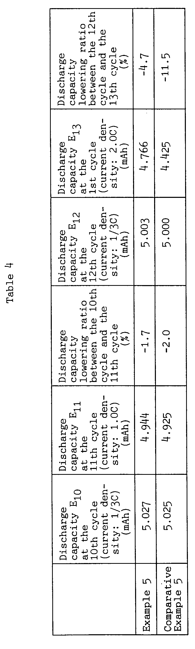


Claims (14)
- A battery comprising:a casing,an electrolyte contained in said casing,a positive electrode comprising a cathode active material layer,a negative electrode comprising an anode active material layer, anda porous separator disposed between said positive electrode and said negative electrode, wherein two opposite surfaces of said porous separator face said cathode active material layer and said anode active material layer, respectively,said positive electrode, said negative electrode and said separator being disposed in said casing, operatively with said electrolyte,said porous separator comprising at least one layer of an aggregate form of particles of at least one insulating substance, wherein said at least one layer of the aggregate form of particles has a three-dimensional network of voids which function as pores in said porous separator and which are capable of passing ions therethough.
- The battery according to claim 1, wherein said porous separator further comprises a binder which is mixed with said particles to thereby bind said particles together.
- The battery according to claim 1 or 2, wherein said porous separator is directly formed, in an immobilized form, on at least one active material layer selected from the group consisting of said cathode active material layer and said anode active material layer.
- The battery according to any one of claims 1 to 3, wherein said porous separator has a porosity of 10 % or more as measured in the dry state of said porous separator.
- The battery according to any one of claims 1 to 4, wherein said porous separator has an ion conductive property ascribed to a factor other than said voids of said aggregate form of particles.
- The battery according to any one of claims 1 to 5, wherein said insulating substance is an inorganic substance.
- The battery according to any one of claims 1 to 5, wherein said insulating substance is an organic substance.
- The battery according to any one of claims 1 to 7, wherein said aggregate form of particles comprises particles of at least two different insulating substances.
- The battery according to any one of claims 1 to 8, wherein said porous separator comprises at least two layers respectively comprised of different aggregate forms of particles.
- The battery according to any one of claims 1 to 9, wherein said separator comprises a first separator layer comprising at least one layer of an aggregate form of particles of at least one inorganic insulating substance and a second separator layer comprising at least one layer of an aggregate form of particles of at least one organic insulating substance, said first separator layer being directly formed, in an immobilized form, on one active material layer selected from said cathode active material layer and said anode active material layer, said second separator layer being directly formed, in an immobilized form, on the other active material layer remaining between said cathode active material layer and said anode active material layer.
- The battery according to any one of claims 1 to 10, wherein said electrolyte is a non-aqueous electrolyte.
- The battery according to claim 11, wherein said non-aqueous electrolyte contains lithium ions.
- The battery according to claim 11 or 12, wherein said cathode active material layer comprises lithium manganate.
- A method for producing a battery, comprising:(1) individually providing a positive electrode comprising a cathode active material layer and a negative electrode comprising an anode active material layer;(2) coating a dispersion of a mixture of particles of at least one insulating substance and a binder for said particles in a dispersion medium on at least one active material layer selected from the group consisting of said cathode active material layer and said anode active material layer;(3) removing, by evaporation, the dispersion medium of said dispersion coated on said at least one active material layer to form a layer of an aggregate form of said particles, wherein said particles are bound together by means of said binder, thereby providing a porous separator formed directly, in an immobilized form, on said at least one active material layer, wherein said layer of an aggregate form of particles has a three dimensional network of voids; and(4) disposing said positive electrode and said negative electrode, at least one of which has the porous separator formed on the active material layer thereof, in a casing so that said cathode active material layer and said anode active material layer are arranged, operatively with an electrolyte contained in said casing, in a positional relationship opposite to each other through the porous separator formed on said at least one active material layer.
Applications Claiming Priority (3)
| Application Number | Priority Date | Filing Date | Title |
|---|---|---|---|
| JP21903695 | 1995-08-28 | ||
| JP219036/95 | 1995-08-28 | ||
| PCT/JP1996/002414 WO1997008763A1 (en) | 1995-08-28 | 1996-08-28 | Cell and production method thereof |
Publications (3)
| Publication Number | Publication Date |
|---|---|
| EP0848435A1 true EP0848435A1 (en) | 1998-06-17 |
| EP0848435A4 EP0848435A4 (en) | 2004-08-04 |
| EP0848435B1 EP0848435B1 (en) | 2007-05-16 |
Family
ID=16729257
Family Applications (1)
| Application Number | Title | Priority Date | Filing Date |
|---|---|---|---|
| EP96928681A Expired - Lifetime EP0848435B1 (en) | 1995-08-28 | 1996-08-28 | Lithium battery and production method thereof |
Country Status (9)
| Country | Link |
|---|---|
| US (1) | US6287720B1 (en) |
| EP (1) | EP0848435B1 (en) |
| JP (1) | JP3253632B2 (en) |
| KR (1) | KR100289973B1 (en) |
| CN (1) | CN1134078C (en) |
| CA (1) | CA2226366C (en) |
| DE (1) | DE69637084T2 (en) |
| TW (1) | TW411636B (en) |
| WO (1) | WO1997008763A1 (en) |
Cited By (16)
| Publication number | Priority date | Publication date | Assignee | Title |
|---|---|---|---|---|
| US6183907B1 (en) * | 1997-08-04 | 2001-02-06 | Alcatel | Binder for an electrode of an electrochemical system with a non-aqueous electrolyte |
| US6488721B1 (en) | 2000-06-09 | 2002-12-03 | Moltech Corporation | Methods of preparing electrochemical cells |
| WO2006004366A1 (en) | 2004-07-07 | 2006-01-12 | Lg Chem, Ltd. | New organic/inorganic composite porous film and electrochemical device prepared thereby |
| EP1296390A4 (en) * | 2000-06-30 | 2006-11-29 | Matsushita Electric Industrial Co Ltd | ELECTRODE PLATE FOR CELL, METHOD FOR MANUFACTURING SAME, AND NONAQUEOUS ELECTROLYTIC SECONDARY CELL USING THE SAME |
| US7179563B2 (en) | 2002-07-10 | 2007-02-20 | Samsung Sdi Co., Ltd. | Binder for a lithium-sulfur battery, positive active material composition comprising same and lithium-sulfur battery using same |
| EP1784876A1 (en) | 2004-09-02 | 2007-05-16 | LG Chem, Ltd. | Organic/inorganic composite porous film and electrochemical device prepared thereby |
| EP1829139A1 (en) | 2004-12-22 | 2007-09-05 | LG Chemical Co. Ltd | Organic/inorganic composite microporous membrane and electrochemical device prepared thereby |
| EP2851974A4 (en) * | 2012-05-17 | 2015-11-04 | Toyota Motor Co Ltd | PROCESS FOR PRODUCING A CELL |
| US20170084917A1 (en) * | 2014-03-27 | 2017-03-23 | Sanyo Electric Co., Ltd. | Nonaqueous electrolyte secondary batteries |
| US10381623B2 (en) | 2015-07-09 | 2019-08-13 | Optodot Corporation | Nanoporous separators for batteries and related manufacturing methods |
| US10403874B2 (en) | 2009-05-26 | 2019-09-03 | Optodot Corporation | Methods of producing batteries utilizing anode metal depositions directly on nanoporous separators |
| US10511021B2 (en) * | 2014-03-17 | 2019-12-17 | Sanyo Electric Co., Ltd. | Non-aqueous electrolyte secondary battery |
| US12278344B2 (en) | 2022-12-16 | 2025-04-15 | 24M Technologies, Inc. | Systems and methods for minimizing and preventing dendrite formation in electrochemical cells |
| US12401088B2 (en) | 2021-04-29 | 2025-08-26 | 24M Technologies, Inc. | Electrochemical cells with multiple separators, and methods of producing the same |
| US12431545B1 (en) | 2024-03-26 | 2025-09-30 | 24M Technologies, Inc. | Systems and methods for minimizing and preventing dendrite formation in electrochemical cells |
| US12567651B2 (en) | 2013-04-29 | 2026-03-03 | 24M Technologies, Inc. | Nanoporous composite separators with increased thermal conductivity |
Families Citing this family (118)
| Publication number | Priority date | Publication date | Assignee | Title |
|---|---|---|---|---|
| US5882721A (en) * | 1997-05-01 | 1999-03-16 | Imra America Inc | Process of manufacturing porous separator for electrochemical power supply |
| EP0954042B1 (en) * | 1997-11-19 | 2007-09-05 | Mitsubishi Denki Kabushiki Kaisha | Lithium ion secondary battery and manufacture thereof |
| US6811928B2 (en) * | 1998-01-22 | 2004-11-02 | Mitsubishi Denki Kabushiki Kaisha | Battery with adhesion resin layer including filler |
| JP4031405B2 (en) * | 1998-09-17 | 2008-01-09 | 株式会社東芝 | Non-aqueous electrolyte secondary battery |
| US6451484B1 (en) * | 1999-04-21 | 2002-09-17 | Samsung Sdi Co., Ltd. | Lithium secondary battery and manufacturing method thereof |
| JP4664455B2 (en) * | 1999-05-11 | 2011-04-06 | 株式会社東芝 | Non-aqueous electrolyte secondary battery |
| US20020102456A1 (en) * | 1999-09-20 | 2002-08-01 | Mitsubishi Denki Kabushiki Kaisha | Battery |
| US20030170536A1 (en) * | 1999-09-22 | 2003-09-11 | Mitsubishi Denki Kabushiki Kaisha | Bttery with adhesion resin layer including filler |
| US6432586B1 (en) | 2000-04-10 | 2002-08-13 | Celgard Inc. | Separator for a high energy rechargeable lithium battery |
| EP1291952A1 (en) * | 2000-06-07 | 2003-03-12 | Gs-Melcotec Co.; Ltd. | Battery |
| KR100362497B1 (en) * | 2000-10-19 | 2002-11-23 | 베스 주식회사 | Porous polymeric electrolyte and method for making the same |
| US7387851B2 (en) * | 2001-07-27 | 2008-06-17 | A123 Systems, Inc. | Self-organizing battery structure with electrode particles that exert a repelling force on the opposite electrode |
| KR101249133B1 (en) * | 2000-10-20 | 2013-04-02 | 매사츄세츠 인스티튜트 오브 테크놀러지 | Bipolar device |
| US6727017B1 (en) * | 2001-04-06 | 2004-04-27 | Changs Ascending Enterprise Co., Ltd. | Methods of fabricating binding layers for a Li-ion polymer battery |
| WO2003012908A2 (en) | 2001-07-27 | 2003-02-13 | Massachusetts Institute Of Technology | Battery structures, self-organizing structures and related methods |
| JP4228177B2 (en) * | 2002-04-24 | 2009-02-25 | 日本電気株式会社 | Secondary battery and battery using the same |
| WO2004012286A1 (en) | 2002-07-26 | 2004-02-05 | A123 Systems, Inc. | Bipolar articles and related methods |
| DE10238943B4 (en) * | 2002-08-24 | 2013-01-03 | Evonik Degussa Gmbh | Separator-electrode unit for lithium-ion batteries, method for their production and use in lithium batteries and a battery, comprising the separator-electrode unit |
| CN1732587B (en) * | 2002-12-27 | 2010-10-06 | 松下电器产业株式会社 | Electrochemical element and its manufacturing method |
| JP2004342329A (en) * | 2003-05-12 | 2004-12-02 | Nippon Paint Co Ltd | Coating method of insulated wire having edge portion and insulated wire |
| US7396612B2 (en) * | 2003-07-29 | 2008-07-08 | Matsushita Electric Industrial Co., Ltd. | Lithium ion secondary battery |
| JP4605389B2 (en) * | 2003-07-31 | 2011-01-05 | 日本電気株式会社 | Lithium ion secondary battery |
| EP1661195B1 (en) * | 2003-08-18 | 2016-01-13 | PowerGenix Systems, Inc. | Method of manufacturing nickel zinc batteries |
| AU2003264403A1 (en) * | 2003-09-10 | 2005-04-06 | Mitsubishi Plastics, Inc. | Fuel cell separator |
| JP4439226B2 (en) * | 2003-09-11 | 2010-03-24 | 日立マクセル株式会社 | Nonaqueous electrolyte secondary battery |
| KR100611940B1 (en) * | 2003-11-21 | 2006-08-11 | 주식회사 엘지화학 | Improved safety electrochemical cell |
| JP3953026B2 (en) * | 2003-12-12 | 2007-08-01 | 松下電器産業株式会社 | Electrode plate for lithium ion secondary battery, lithium ion secondary battery and method for producing the same |
| JP4694968B2 (en) * | 2004-01-05 | 2011-06-08 | パナソニック株式会社 | Lithium secondary battery |
| DE602005011264D1 (en) * | 2004-02-18 | 2009-01-08 | Panasonic Corp | SECONDARY BATTERY |
| KR100790280B1 (en) * | 2004-03-30 | 2008-01-02 | 마쯔시다덴기산교 가부시키가이샤 | Nonaqueous Electrolyte Secondary Battery |
| KR100856638B1 (en) * | 2004-03-30 | 2008-09-03 | 마쯔시다덴기산교 가부시키가이샤 | Lithium ion secondary battery and charge/discharge controlling system thereof |
| JP4649862B2 (en) * | 2004-04-02 | 2011-03-16 | パナソニック株式会社 | Lithium ion secondary battery and manufacturing method thereof |
| JP4794824B2 (en) * | 2004-04-05 | 2011-10-19 | パナソニック株式会社 | Lithium ion secondary battery and manufacturing method thereof |
| JP4781263B2 (en) * | 2004-06-22 | 2011-09-28 | パナソニック株式会社 | Secondary battery and manufacturing method thereof |
| KR100635761B1 (en) * | 2004-06-25 | 2006-10-17 | 삼성에스디아이 주식회사 | Electrode assembly and secondary battery using same |
| TWI318018B (en) * | 2004-09-02 | 2009-12-01 | Lg Chemical Ltd | Organic/inorganic composite porous film and electrochemical device prepared thereby |
| WO2006045339A2 (en) * | 2004-10-21 | 2006-05-04 | Degussa Ag | Inorganic separator-electrode-unit for lithium-ion batteries, method for the production thereof and use thereof in lithium batteries |
| KR100659820B1 (en) * | 2004-11-17 | 2006-12-19 | 삼성에스디아이 주식회사 | Lithium ion secondary battery |
| KR100758482B1 (en) * | 2004-12-07 | 2007-09-12 | 주식회사 엘지화학 | Surface-treated microporous membrane and electrochemical device prepared thereby |
| US11050095B2 (en) * | 2004-12-08 | 2021-06-29 | Maxell Holdings, Ltd. | Separator for electrochemical device, and electrochemical device |
| US8187748B2 (en) * | 2004-12-24 | 2012-05-29 | Panasonic Corporation | Non-aqueous electrolyte secondary battery |
| WO2006068143A1 (en) * | 2004-12-24 | 2006-06-29 | Matsushita Electric Industrial Co., Ltd. | Rechargeable battery with nonaqueous electrolyte |
| JP2006216511A (en) * | 2005-02-07 | 2006-08-17 | Sanyo Electric Co Ltd | Nonaqueous electrolyte secondary battery |
| JP2006228544A (en) * | 2005-02-17 | 2006-08-31 | Matsushita Electric Ind Co Ltd | Lithium ion secondary battery |
| EP1780820A4 (en) * | 2005-03-02 | 2009-09-09 | Panasonic Corp | LITHIUM ION SECONDARY BATTERY AND METHOD OF MANUFACTURING THE SAME |
| KR100838933B1 (en) * | 2005-04-04 | 2008-06-16 | 마쯔시다덴기산교 가부시키가이샤 | Lithium secondary battery |
| EP1768202A1 (en) * | 2005-04-04 | 2007-03-28 | Matsusita Electric Industrial Co., Ltd. | Cylindrical lithium secondary battery |
| US8703330B2 (en) * | 2005-04-26 | 2014-04-22 | Powergenix Systems, Inc. | Nickel zinc battery design |
| KR100821442B1 (en) * | 2005-05-31 | 2008-04-10 | 마쯔시다덴기산교 가부시키가이샤 | Non-aqueous electrolyte secondary battery and battery module |
| JP4992203B2 (en) * | 2005-06-24 | 2012-08-08 | 日本ゼオン株式会社 | Lithium ion secondary battery |
| KR100770105B1 (en) * | 2005-07-06 | 2007-10-24 | 삼성에스디아이 주식회사 | Lithium secondary battery |
| WO2007080456A2 (en) * | 2005-08-30 | 2007-07-19 | Railpower Technologies Corp. | Electrochemical cell for hybrid electric vehicle applications |
| US20090291355A1 (en) * | 2005-09-29 | 2009-11-26 | Sanyo Electric Co., Ltd. | Positive electrode for non-aqueous electrolyte battery, negative electrode for non-aqueous electrolyte battery, separator for non-aqueous electrolyte battery, and non-aqueous electrolyte battery using them |
| EP1770817A3 (en) * | 2005-09-29 | 2007-12-05 | Air Products and Chemicals, Inc. | Surface-lithiated metal oxide nanoparticles for lithium battery electrolytes |
| KR100686848B1 (en) * | 2005-10-11 | 2007-02-26 | 삼성에스디아이 주식회사 | Lithium secondary battery |
| JP4151852B2 (en) * | 2005-12-08 | 2008-09-17 | 日立マクセル株式会社 | Electrochemical element separator and manufacturing method thereof, and electrochemical element and manufacturing method thereof |
| US8883354B2 (en) | 2006-02-15 | 2014-11-11 | Optodot Corporation | Separators for electrochemical cells |
| JP5135822B2 (en) * | 2006-02-21 | 2013-02-06 | 日産自動車株式会社 | Lithium ion secondary battery and battery pack using the same |
| JP5137312B2 (en) * | 2006-03-17 | 2013-02-06 | 三洋電機株式会社 | Non-aqueous electrolyte battery |
| JP5093439B2 (en) * | 2006-04-04 | 2012-12-12 | ソニー株式会社 | Secondary battery |
| CN101479877B (en) * | 2006-05-04 | 2013-07-31 | 株式会社Lg化学 | Lithium secondary battery and manufacturing method thereof |
| JP5403857B2 (en) * | 2006-05-18 | 2014-01-29 | 日立マクセル株式会社 | Battery separator, method for producing the same, and lithium secondary battery |
| KR101079456B1 (en) * | 2006-05-22 | 2011-11-03 | 파나소닉 주식회사 | Separator and nonaqueous electrolyte secondary battery |
| JP4724223B2 (en) * | 2006-09-07 | 2011-07-13 | 日立マクセル株式会社 | Manufacturing method of battery separator |
| EP2070137B1 (en) * | 2006-09-25 | 2014-10-29 | LG Chem, Ltd. | Method for identifying the origin or kind of a separator itself or of an electrochemical device having the separator |
| JP5298419B2 (en) * | 2006-10-16 | 2013-09-25 | ソニー株式会社 | Secondary battery |
| US20080118848A1 (en) * | 2006-11-16 | 2008-05-22 | Electronics & Telecommunications Research Institute | Aqeuous electrolyte composition and sealed-type primary film battery including electrolyte layer formed of the aqueous electrolyte composition |
| JP5157354B2 (en) * | 2006-11-30 | 2013-03-06 | 日産自動車株式会社 | Bipolar battery and manufacturing method thereof |
| KR100914108B1 (en) * | 2007-05-03 | 2009-08-27 | 삼성에스디아이 주식회사 | Electrode assembly and secondary battery having same |
| US20090202903A1 (en) | 2007-05-25 | 2009-08-13 | Massachusetts Institute Of Technology | Batteries and electrodes for use thereof |
| JP2009188037A (en) * | 2008-02-04 | 2009-08-20 | Fuji Heavy Ind Ltd | Power storage device |
| JP5059643B2 (en) * | 2008-02-04 | 2012-10-24 | ソニー株式会社 | Non-aqueous electrolyte battery |
| US20110033755A1 (en) * | 2008-04-21 | 2011-02-10 | Seeo, Inc | Protected lithium metal electrodes for rechargeable batteries |
| EP2272124B1 (en) * | 2008-04-02 | 2016-03-23 | PowerGenix Systems, Inc. | Cylindrical nickel-zinc cell with negative can |
| JP2009277597A (en) * | 2008-05-16 | 2009-11-26 | Panasonic Corp | Nonaqueous electrolyte secondary battery |
| WO2010008003A1 (en) * | 2008-07-16 | 2010-01-21 | 東レ株式会社 | Separator for electricity storage device |
| JP2010097756A (en) * | 2008-10-15 | 2010-04-30 | Sony Corp | Secondary battery |
| JP5621248B2 (en) * | 2009-02-03 | 2014-11-12 | ソニー株式会社 | Separator and battery |
| DE102009017542A1 (en) * | 2009-04-17 | 2010-10-28 | Carl Freudenberg Kg | Unsymmetrical separator |
| JP2010267475A (en) * | 2009-05-14 | 2010-11-25 | Panasonic Corp | Lithium ion secondary battery |
| KR20120062713A (en) * | 2009-08-19 | 2012-06-14 | 미쓰비시 쥬시 가부시끼가이샤 | Separator for non-aqueous electrolyte secondary battery and non-aqueous electrolyte secondary battery |
| KR101093859B1 (en) * | 2009-09-02 | 2011-12-13 | 삼성에스디아이 주식회사 | Electrode plate, electrode assembly and manufacturing method of the electrode plate |
| CH701976A2 (en) * | 2009-10-02 | 2011-04-15 | Oxyphen Ag | Electrochemical energy storage with separator. |
| JP5509816B2 (en) | 2009-11-30 | 2014-06-04 | ソニー株式会社 | Separator, battery using the separator, and microporous membrane |
| JP2011119097A (en) * | 2009-12-02 | 2011-06-16 | Sony Corp | Nonaqueous electrolyte battery |
| US9142833B2 (en) * | 2010-06-07 | 2015-09-22 | The Regents Of The University Of California | Lithium ion batteries based on nanoporous silicon |
| PL2596538T3 (en) | 2010-07-19 | 2019-06-28 | Optodot Corporation | Separators for electrochemical cells |
| CN103229341B (en) * | 2010-11-24 | 2015-12-16 | 丰田自动车株式会社 | Battery and battery manufacturing method |
| JP5832915B2 (en) * | 2011-02-24 | 2015-12-16 | 株式会社日立製作所 | Method for manufacturing lithium ion battery |
| US9065093B2 (en) | 2011-04-07 | 2015-06-23 | Massachusetts Institute Of Technology | Controlled porosity in electrodes |
| US9287540B2 (en) | 2011-05-31 | 2016-03-15 | GM Global Technology Operations LLC | Separators for a lithium ion battery |
| KR101649130B1 (en) * | 2011-10-20 | 2016-08-19 | 삼성에스디아이 주식회사 | Lithium secondary battery |
| JP5920060B2 (en) * | 2012-07-02 | 2016-05-18 | 株式会社豊田中央研究所 | Method of using non-aqueous electrolyte battery and non-aqueous electrolyte battery |
| JP5624653B2 (en) | 2012-07-24 | 2014-11-12 | 株式会社東芝 | Secondary battery |
| CN103794814B (en) * | 2012-10-29 | 2016-04-13 | 比亚迪股份有限公司 | A kind of lithium ion battery and preparation method thereof |
| KR101586881B1 (en) * | 2013-08-29 | 2016-01-19 | 주식회사 엘지화학 | Electrode assembly for cell of polymer lithium secondary battery |
| US9680143B2 (en) | 2013-10-18 | 2017-06-13 | Miltec Uv International Llc | Polymer-bound ceramic particle battery separator coating |
| US10818900B2 (en) | 2014-07-18 | 2020-10-27 | Miltec UV International, LLC | UV or EB cured polymer-bonded ceramic particle lithium secondary battery separators, method for the production thereof |
| US10569480B2 (en) | 2014-10-03 | 2020-02-25 | Massachusetts Institute Of Technology | Pore orientation using magnetic fields |
| US10675819B2 (en) | 2014-10-03 | 2020-06-09 | Massachusetts Institute Of Technology | Magnetic field alignment of emulsions to produce porous articles |
| JP6210050B2 (en) * | 2014-11-12 | 2017-10-11 | トヨタ自動車株式会社 | Fuel cell |
| US12040506B2 (en) | 2015-04-15 | 2024-07-16 | Lg Energy Solution, Ltd. | Nanoporous separators for batteries and related manufacturing methods |
| US20160372727A1 (en) * | 2015-06-17 | 2016-12-22 | Johns Manville | Bi-functional nonwoven mat used in agm lead-acid batteries |
| US11139478B2 (en) * | 2017-07-21 | 2021-10-05 | Zeon Corporation | Laminate for non-aqueous secondary battery, non-aqueous secondary battery, and non-aqueous secondary battery production method |
| US10038193B1 (en) | 2017-07-28 | 2018-07-31 | EnPower, Inc. | Electrode having an interphase structure |
| JP6978273B2 (en) * | 2017-10-24 | 2021-12-08 | 住友化学株式会社 | Water-based paint |
| US20210175580A1 (en) * | 2018-04-16 | 2021-06-10 | Board Of Regents, The University Of Texas System | Electrochemical devices and methods of making and use thereof |
| TWI894136B (en) | 2019-03-03 | 2025-08-21 | 美商星塵電力有限責任公司 | Flow-through electrochemical cell |
| US11569550B2 (en) | 2019-04-05 | 2023-01-31 | EnPower, Inc. | Electrode with integrated ceramic separator |
| US10998553B1 (en) * | 2019-10-31 | 2021-05-04 | EnPower, Inc. | Electrochemical cell with integrated ceramic separator |
| CN112751142B (en) * | 2019-10-31 | 2023-05-23 | 美商映能量公司 | Electrochemical cell with integrated ceramic separator |
| KR20220152286A (en) | 2020-03-12 | 2022-11-15 | 폴 링컨 싱클레어 | Flow-through electrochemical cell with a permeable membrane |
| JP2024519593A (en) * | 2021-05-20 | 2024-05-17 | アリゾナ ボード オブ リージェンツ オン ビハーフ オブ アリゾナ ステート ユニバーシティ | Zeolite separator coated plate structure electrodes for lithium metal batteries |
| US11594784B2 (en) | 2021-07-28 | 2023-02-28 | EnPower, Inc. | Integrated fibrous separator |
| CN117154341A (en) | 2022-05-23 | 2023-12-01 | 通用汽车环球科技运作有限责任公司 | Polymer barrier for solid state battery |
| US12266793B2 (en) | 2023-06-01 | 2025-04-01 | Unigrid, Inc. | Electrodes, electrode materials, and manufacturing thereof |
| US12002927B1 (en) * | 2023-08-04 | 2024-06-04 | Unigrid, Inc. | Electrolytes, electrodes, electrolytes and electrodes materials, and manufacturing thereof |
| EP4675688A1 (en) * | 2024-07-03 | 2026-01-07 | LG Energy Solution, Ltd. | Battery manufacturing method and corresponding battery |
Family Cites Families (20)
| Publication number | Priority date | Publication date | Assignee | Title |
|---|---|---|---|---|
| US3736186A (en) * | 1971-06-16 | 1973-05-29 | Mallory & Co Inc P R | Separator and electrolyte material for solid electrolyte battery systems |
| US4144301A (en) * | 1972-09-25 | 1979-03-13 | The Secretary Of State For Defence In Her Britannic Majesty's Government Of The United Kingdom Of Great Britain And Northern Ireland | Separators for electrolytic cells |
| US4283469A (en) * | 1980-03-31 | 1981-08-11 | Gte Products Corp. | Integrated electrode/separator structures |
| JPS56160756A (en) * | 1980-05-14 | 1981-12-10 | Nec Corp | Cell |
| JPS59169075A (en) * | 1983-03-16 | 1984-09-22 | Japan Storage Battery Co Ltd | molten salt battery |
| US4707422A (en) * | 1983-06-27 | 1987-11-17 | Voltaix, Inc. | Composite coating for electrochemical electrode and method |
| JPS63126177A (en) * | 1985-04-16 | 1988-05-30 | Yuasa Battery Co Ltd | Organic electrolytic solution battery and its manufacture |
| JPS6427160A (en) * | 1987-07-22 | 1989-01-30 | Shin Kobe Electric Machinery | Lithium secondary battery |
| JP2520310B2 (en) | 1989-09-19 | 1996-07-31 | 東燃株式会社 | Method for manufacturing separator for lithium battery |
| JPH03283259A (en) * | 1990-03-29 | 1991-12-13 | Asahi Chem Ind Co Ltd | Battery |
| JP3291750B2 (en) * | 1992-02-25 | 2002-06-10 | 松下電器産業株式会社 | Non-aqueous electrolyte secondary battery and method of manufacturing the same |
| JP3191394B2 (en) * | 1992-04-10 | 2001-07-23 | 松下電器産業株式会社 | Manufacturing method of non-aqueous secondary battery and its negative electrode plate |
| CA2110097C (en) * | 1992-11-30 | 2002-07-09 | Soichiro Kawakami | Secondary battery |
| JPH06251759A (en) * | 1993-02-22 | 1994-09-09 | Japan Storage Battery Co Ltd | Lead acid battery separator |
| JPH08213052A (en) * | 1994-08-04 | 1996-08-20 | Seiko Instr Inc | Nonaqueous electrolyte secondary battery |
| US6365299B1 (en) | 1995-06-28 | 2002-04-02 | Fuji Photo Film Co., Ltd. | Nonaqueous secondary battery |
| US5665491A (en) * | 1995-12-11 | 1997-09-09 | Fuji Photo Film Co., Ltd. | Nonaqueous secondary battery |
| KR100373724B1 (en) * | 1995-12-15 | 2003-05-16 | 삼성에스디아이 주식회사 | Cathode and Cathode Plates for Alkaline Batteries and Manufacturing Method |
| JPH09245836A (en) * | 1996-03-08 | 1997-09-19 | Fuji Photo Film Co Ltd | Nonaqueous electrolyte secondary battery |
| US5882721A (en) * | 1997-05-01 | 1999-03-16 | Imra America Inc | Process of manufacturing porous separator for electrochemical power supply |
-
1996
- 1996-08-28 CA CA002226366A patent/CA2226366C/en not_active Expired - Lifetime
- 1996-08-28 TW TW085110568A patent/TW411636B/en not_active IP Right Cessation
- 1996-08-28 KR KR1019980700279A patent/KR100289973B1/en not_active Expired - Fee Related
- 1996-08-28 JP JP51012497A patent/JP3253632B2/en not_active Expired - Lifetime
- 1996-08-28 CN CNB961955961A patent/CN1134078C/en not_active Expired - Lifetime
- 1996-08-28 WO PCT/JP1996/002414 patent/WO1997008763A1/en not_active Ceased
- 1996-08-28 US US08/981,092 patent/US6287720B1/en not_active Expired - Lifetime
- 1996-08-28 DE DE69637084T patent/DE69637084T2/en not_active Expired - Lifetime
- 1996-08-28 EP EP96928681A patent/EP0848435B1/en not_active Expired - Lifetime
Cited By (32)
| Publication number | Priority date | Publication date | Assignee | Title |
|---|---|---|---|---|
| US6183907B1 (en) * | 1997-08-04 | 2001-02-06 | Alcatel | Binder for an electrode of an electrochemical system with a non-aqueous electrolyte |
| US6488721B1 (en) | 2000-06-09 | 2002-12-03 | Moltech Corporation | Methods of preparing electrochemical cells |
| EP1296390A4 (en) * | 2000-06-30 | 2006-11-29 | Matsushita Electric Industrial Co Ltd | ELECTRODE PLATE FOR CELL, METHOD FOR MANUFACTURING SAME, AND NONAQUEOUS ELECTROLYTIC SECONDARY CELL USING THE SAME |
| US7179563B2 (en) | 2002-07-10 | 2007-02-20 | Samsung Sdi Co., Ltd. | Binder for a lithium-sulfur battery, positive active material composition comprising same and lithium-sulfur battery using same |
| WO2006004366A1 (en) | 2004-07-07 | 2006-01-12 | Lg Chem, Ltd. | New organic/inorganic composite porous film and electrochemical device prepared thereby |
| EP1782489A1 (en) | 2004-07-07 | 2007-05-09 | LG Chem, Ltd. | New organic/inorganic composite porous film and electrochemical device prepared thereby |
| EP1782489B1 (en) * | 2004-07-07 | 2020-11-18 | LG Chem, Ltd. | Organic/inorganic composite porous separator and electrochemical device comprasing the same. |
| EP1784876A1 (en) | 2004-09-02 | 2007-05-16 | LG Chem, Ltd. | Organic/inorganic composite porous film and electrochemical device prepared thereby |
| EP2528142A2 (en) | 2004-12-22 | 2012-11-28 | LG Chem, Ltd. | Organic/inorganic composite microporous membrane and electrochemical device prepared thereby |
| EP1829139B1 (en) * | 2004-12-22 | 2014-01-01 | LG Chem, Ltd | Organic/inorganic composite microporous membrane and electrochemical device prepared thereby |
| EP1829139A1 (en) | 2004-12-22 | 2007-09-05 | LG Chemical Co. Ltd | Organic/inorganic composite microporous membrane and electrochemical device prepared thereby |
| US10403874B2 (en) | 2009-05-26 | 2019-09-03 | Optodot Corporation | Methods of producing batteries utilizing anode metal depositions directly on nanoporous separators |
| US11777176B2 (en) | 2009-05-26 | 2023-10-03 | Meta Materials Inc. | Lithium batteries utilizing nanoporous separator layers |
| EP2851974A4 (en) * | 2012-05-17 | 2015-11-04 | Toyota Motor Co Ltd | PROCESS FOR PRODUCING A CELL |
| US12567651B2 (en) | 2013-04-29 | 2026-03-03 | 24M Technologies, Inc. | Nanoporous composite separators with increased thermal conductivity |
| US10511021B2 (en) * | 2014-03-17 | 2019-12-17 | Sanyo Electric Co., Ltd. | Non-aqueous electrolyte secondary battery |
| US20170084917A1 (en) * | 2014-03-27 | 2017-03-23 | Sanyo Electric Co., Ltd. | Nonaqueous electrolyte secondary batteries |
| US10096829B2 (en) * | 2014-03-27 | 2018-10-09 | Sanyo Electric Co., Ltd. | Nonaqueous electrolyte secondary batteries |
| US10381623B2 (en) | 2015-07-09 | 2019-08-13 | Optodot Corporation | Nanoporous separators for batteries and related manufacturing methods |
| US12407065B2 (en) | 2021-04-29 | 2025-09-02 | 24M Technologies, Inc. | Electrochemical cells with multiple separators, and methods of producing the same |
| US12401088B2 (en) | 2021-04-29 | 2025-08-26 | 24M Technologies, Inc. | Electrochemical cells with multiple separators, and methods of producing the same |
| US12401089B2 (en) | 2021-04-29 | 2025-08-26 | 24M Technologies, Inc. | Electrochemical cells with multiple separators, and methods of producing the same |
| US12456780B2 (en) | 2021-04-29 | 2025-10-28 | 24M Technologies, Inc. | Electrochemical cells with multiple separators, and methods of producing the same |
| US12322763B2 (en) | 2022-12-16 | 2025-06-03 | 24M Technologies, Inc. | Systems and methods for minimizing and preventing dendrite formation in electrochemical cells |
| US12334518B1 (en) | 2022-12-16 | 2025-06-17 | 24M Technologies, Inc. | Systems and methods for minimizing and preventing dendrite formation in electrochemical cells |
| US12322762B2 (en) | 2022-12-16 | 2025-06-03 | 24M Technologies, Inc. | Systems and methods for minimizing and preventing dendrite formation in electrochemical cells |
| US12476288B2 (en) | 2022-12-16 | 2025-11-18 | 24M Technologies, Inc. | Systems and methods for minimizing and preventing dendrite formation in electrochemical cells |
| US12500278B2 (en) | 2022-12-16 | 2025-12-16 | 24M Technologies, Inc. | Systems and methods for minimizing and preventing dendrite formation in electrochemical cells |
| US12278344B2 (en) | 2022-12-16 | 2025-04-15 | 24M Technologies, Inc. | Systems and methods for minimizing and preventing dendrite formation in electrochemical cells |
| US12580231B2 (en) | 2022-12-16 | 2026-03-17 | 24M Technologies, Inc. | Systems and methods for minimizing and preventing dendrite formation in electrochemical cells |
| US12431545B1 (en) | 2024-03-26 | 2025-09-30 | 24M Technologies, Inc. | Systems and methods for minimizing and preventing dendrite formation in electrochemical cells |
| US12542306B2 (en) | 2024-03-26 | 2026-02-03 | 24M Technologies, Inc. | Systems and methods for minimizing and preventing dendrite formation in electrochemical cells |
Also Published As
| Publication number | Publication date |
|---|---|
| CN1191041A (en) | 1998-08-19 |
| JP3253632B2 (en) | 2002-02-04 |
| US6287720B1 (en) | 2001-09-11 |
| KR100289973B1 (en) | 2001-05-15 |
| WO1997008763A1 (en) | 1997-03-06 |
| CA2226366A1 (en) | 1997-03-06 |
| EP0848435B1 (en) | 2007-05-16 |
| EP0848435A4 (en) | 2004-08-04 |
| KR19990028977A (en) | 1999-04-15 |
| DE69637084D1 (en) | 2007-06-28 |
| CN1134078C (en) | 2004-01-07 |
| DE69637084T2 (en) | 2008-02-07 |
| CA2226366C (en) | 2002-05-21 |
| TW411636B (en) | 2000-11-11 |
Similar Documents
| Publication | Publication Date | Title |
|---|---|---|
| US6287720B1 (en) | Nonaqueous battery having porous separator and production method thereof | |
| US9166250B2 (en) | Separator for battery, method for manufacturing the same, and lithium secondary battery | |
| US8405957B2 (en) | Separator for electrochemical device and method for producing the same, and electrochemical device and method for producing the same | |
| US8822082B2 (en) | Separator for electrochemical device, electrode for electrochemical device, and electrochemical device | |
| JP3567131B2 (en) | Non-aqueous electrolyte battery | |
| KR101558774B1 (en) | Lithium secondary battery comprising multilayered active materials | |
| AU2009200223B2 (en) | Non-aqueous secondary battery and separator used therefor | |
| JPWO1997008763A1 (en) | New battery and manufacturing method thereof | |
| EP3648197B1 (en) | Electrochemical device including a flame retardant separator having an asymmetric structure | |
| CN103843172B (en) | Dividing plate with heat-resistant insulating layer | |
| JP2005276503A (en) | Battery separator and battery using the same | |
| KR20180028814A (en) | Electrode for lithium secondary battery and lithium secondary battery comprising the same | |
| KR20190026627A (en) | Method of Preparing Flexible Battery, and Flexible Battery Prepared therefrom | |
| EP4266443B1 (en) | Lithium secondary battery and method for manufacturing the same | |
| US12218342B2 (en) | Energy storage device | |
| JPH06181058A (en) | Looseness restraining means of wound electrode body for nonaqueous electrolyte type battery | |
| JP6832474B2 (en) | Positive electrode material for lithium ion secondary battery, positive electrode active material layer, and lithium ion secondary battery | |
| US20230378424A1 (en) | Method for manufacturing negative electrode | |
| JPH09161838A (en) | Battery | |
| CN113906605A (en) | Secondary battery | |
| JP2017039250A (en) | Laminate | |
| US12107273B2 (en) | Nonaqueous electrolyte secondary battery | |
| KR102909166B1 (en) | Electrode for secondary battery and lithium secondary battery including the same | |
| JP2019129145A (en) | Nonaqueous electrolyte battery | |
| CN121862888A (en) | Electrode components and rechargeable batteries |
Legal Events
| Date | Code | Title | Description |
|---|---|---|---|
| PUAI | Public reference made under article 153(3) epc to a published international application that has entered the european phase |
Free format text: ORIGINAL CODE: 0009012 |
|
| 17P | Request for examination filed |
Effective date: 19971211 |
|
| AK | Designated contracting states |
Kind code of ref document: A1 Designated state(s): DE FR GB |
|
| RAP1 | Party data changed (applicant data changed or rights of an application transferred) |
Owner name: ASAHI KASEI KABUSHIKI KAISHA |
|
| A4 | Supplementary search report drawn up and despatched |
Effective date: 20040621 |
|
| RAP1 | Party data changed (applicant data changed or rights of an application transferred) |
Owner name: ASAHI KASEI EMD CORPORATION |
|
| RTI1 | Title (correction) |
Free format text: LITHIUM BATTERY AND PRODUCTION METHOD THEREOF |
|
| GRAP | Despatch of communication of intention to grant a patent |
Free format text: ORIGINAL CODE: EPIDOSNIGR1 |
|
| GRAS | Grant fee paid |
Free format text: ORIGINAL CODE: EPIDOSNIGR3 |
|
| GRAA | (expected) grant |
Free format text: ORIGINAL CODE: 0009210 |
|
| AK | Designated contracting states |
Kind code of ref document: B1 Designated state(s): DE FR GB |
|
| REG | Reference to a national code |
Ref country code: GB Ref legal event code: FG4D |
|
| REF | Corresponds to: |
Ref document number: 69637084 Country of ref document: DE Date of ref document: 20070628 Kind code of ref document: P |
|
| ET | Fr: translation filed | ||
| PLBE | No opposition filed within time limit |
Free format text: ORIGINAL CODE: 0009261 |
|
| STAA | Information on the status of an ep patent application or granted ep patent |
Free format text: STATUS: NO OPPOSITION FILED WITHIN TIME LIMIT |
|
| 26N | No opposition filed |
Effective date: 20080219 |
|
| REG | Reference to a national code |
Ref country code: FR Ref legal event code: PLFP Year of fee payment: 20 |
|
| PGFP | Annual fee paid to national office [announced via postgrant information from national office to epo] |
Ref country code: DE Payment date: 20150825 Year of fee payment: 20 Ref country code: GB Payment date: 20150826 Year of fee payment: 20 |
|
| PGFP | Annual fee paid to national office [announced via postgrant information from national office to epo] |
Ref country code: FR Payment date: 20150629 Year of fee payment: 20 |
|
| REG | Reference to a national code |
Ref country code: DE Ref legal event code: R071 Ref document number: 69637084 Country of ref document: DE |
|
| REG | Reference to a national code |
Ref country code: GB Ref legal event code: PE20 Expiry date: 20160827 |
|
| PG25 | Lapsed in a contracting state [announced via postgrant information from national office to epo] |
Ref country code: GB Free format text: LAPSE BECAUSE OF EXPIRATION OF PROTECTION Effective date: 20160827 |