EP2070137B1 - Method for identifying the origin or kind of a separator itself or of an electrochemical device having the separator - Google Patents
Method for identifying the origin or kind of a separator itself or of an electrochemical device having the separator Download PDFInfo
- Publication number
- EP2070137B1 EP2070137B1 EP07808432.4A EP07808432A EP2070137B1 EP 2070137 B1 EP2070137 B1 EP 2070137B1 EP 07808432 A EP07808432 A EP 07808432A EP 2070137 B1 EP2070137 B1 EP 2070137B1
- Authority
- EP
- European Patent Office
- Prior art keywords
- separator
- inorganic particles
- electrochemical device
- spectrum
- origin
- Prior art date
- Legal status (The legal status is an assumption and is not a legal conclusion. Google has not performed a legal analysis and makes no representation as to the accuracy of the status listed.)
- Active
Links
- 238000000034 method Methods 0.000 title claims description 18
- 239000010954 inorganic particle Substances 0.000 claims description 67
- 238000001228 spectrum Methods 0.000 claims description 28
- 239000000758 substrate Substances 0.000 description 32
- 229920000642 polymer Polymers 0.000 description 21
- 239000003792 electrolyte Substances 0.000 description 20
- 239000002904 solvent Substances 0.000 description 14
- 229910052744 lithium Inorganic materials 0.000 description 12
- 229910019114 CoAl2O4 Inorganic materials 0.000 description 11
- WHXSMMKQMYFTQS-UHFFFAOYSA-N Lithium Chemical compound [Li] WHXSMMKQMYFTQS-UHFFFAOYSA-N 0.000 description 11
- 239000011148 porous material Substances 0.000 description 11
- SECXISVLQFMRJM-UHFFFAOYSA-N N-Methylpyrrolidone Chemical compound CN1CCCC1=O SECXISVLQFMRJM-UHFFFAOYSA-N 0.000 description 10
- VYPSYNLAJGMNEJ-UHFFFAOYSA-N Silicium dioxide Chemical compound O=[Si]=O VYPSYNLAJGMNEJ-UHFFFAOYSA-N 0.000 description 10
- QDOXWKRWXJOMAK-UHFFFAOYSA-N dichromium trioxide Chemical compound O=[Cr]O[Cr]=O QDOXWKRWXJOMAK-UHFFFAOYSA-N 0.000 description 9
- 238000004519 manufacturing process Methods 0.000 description 8
- XOLBLPGZBRYERU-UHFFFAOYSA-N tin dioxide Chemical compound O=[Sn]=O XOLBLPGZBRYERU-UHFFFAOYSA-N 0.000 description 8
- -1 (Co Inorganic materials 0.000 description 7
- JEIPFZHSYJVQDO-UHFFFAOYSA-N iron(III) oxide Inorganic materials O=[Fe]O[Fe]=O JEIPFZHSYJVQDO-UHFFFAOYSA-N 0.000 description 7
- 229910001416 lithium ion Inorganic materials 0.000 description 7
- HBBGRARXTFLTSG-UHFFFAOYSA-N Lithium ion Chemical compound [Li+] HBBGRARXTFLTSG-UHFFFAOYSA-N 0.000 description 6
- 238000000576 coating method Methods 0.000 description 6
- 239000002245 particle Substances 0.000 description 6
- 150000003839 salts Chemical class 0.000 description 6
- 239000002002 slurry Substances 0.000 description 6
- CSCPPACGZOOCGX-UHFFFAOYSA-N Acetone Chemical compound CC(C)=O CSCPPACGZOOCGX-UHFFFAOYSA-N 0.000 description 5
- KMTRUDSVKNLOMY-UHFFFAOYSA-N Ethylene carbonate Chemical compound O=C1OCCO1 KMTRUDSVKNLOMY-UHFFFAOYSA-N 0.000 description 5
- 239000011230 binding agent Substances 0.000 description 5
- 229910052804 chromium Inorganic materials 0.000 description 5
- 239000011248 coating agent Substances 0.000 description 5
- 229910052681 coesite Inorganic materials 0.000 description 5
- 229910052906 cristobalite Inorganic materials 0.000 description 5
- JBTWLSYIZRCDFO-UHFFFAOYSA-N ethyl methyl carbonate Chemical compound CCOC(=O)OC JBTWLSYIZRCDFO-UHFFFAOYSA-N 0.000 description 5
- 239000000377 silicon dioxide Substances 0.000 description 5
- 229910052682 stishovite Inorganic materials 0.000 description 5
- 229910052905 tridymite Inorganic materials 0.000 description 5
- 229910052845 zircon Inorganic materials 0.000 description 5
- RTZKZFJDLAIYFH-UHFFFAOYSA-N Diethyl ether Chemical compound CCOCC RTZKZFJDLAIYFH-UHFFFAOYSA-N 0.000 description 4
- 239000002033 PVDF binder Substances 0.000 description 4
- WYURNTSHIVDZCO-UHFFFAOYSA-N Tetrahydrofuran Chemical compound C1CCOC1 WYURNTSHIVDZCO-UHFFFAOYSA-N 0.000 description 4
- 229910052782 aluminium Inorganic materials 0.000 description 4
- 239000000203 mixture Substances 0.000 description 4
- 229920002981 polyvinylidene fluoride Polymers 0.000 description 4
- WEVYAHXRMPXWCK-UHFFFAOYSA-N Acetonitrile Chemical compound CC#N WEVYAHXRMPXWCK-UHFFFAOYSA-N 0.000 description 3
- YMWUJEATGCHHMB-UHFFFAOYSA-N Dichloromethane Chemical compound ClCCl YMWUJEATGCHHMB-UHFFFAOYSA-N 0.000 description 3
- XEKOWRVHYACXOJ-UHFFFAOYSA-N Ethyl acetate Chemical compound CCOC(C)=O XEKOWRVHYACXOJ-UHFFFAOYSA-N 0.000 description 3
- ZMXDDKWLCZADIW-UHFFFAOYSA-N N,N-Dimethylformamide Chemical compound CN(C)C=O ZMXDDKWLCZADIW-UHFFFAOYSA-N 0.000 description 3
- GWEVSGVZZGPLCZ-UHFFFAOYSA-N Titan oxide Chemical compound O=[Ti]=O GWEVSGVZZGPLCZ-UHFFFAOYSA-N 0.000 description 3
- MCMNRKCIXSYSNV-UHFFFAOYSA-N Zirconium dioxide Chemical compound O=[Zr]=O MCMNRKCIXSYSNV-UHFFFAOYSA-N 0.000 description 3
- 229910000152 cobalt phosphate Inorganic materials 0.000 description 3
- 230000000052 comparative effect Effects 0.000 description 3
- 229910052742 iron Inorganic materials 0.000 description 3
- 229920000098 polyolefin Polymers 0.000 description 3
- 229920000131 polyvinylidene Polymers 0.000 description 3
- 230000008569 process Effects 0.000 description 3
- 238000010298 pulverizing process Methods 0.000 description 3
- 239000004065 semiconductor Substances 0.000 description 3
- 239000000126 substance Substances 0.000 description 3
- 229910052725 zinc Inorganic materials 0.000 description 3
- DHKHKXVYLBGOIT-UHFFFAOYSA-N 1,1-Diethoxyethane Chemical compound CCOC(C)OCC DHKHKXVYLBGOIT-UHFFFAOYSA-N 0.000 description 2
- ZZXUZKXVROWEIF-UHFFFAOYSA-N 1,2-butylene carbonate Chemical compound CCC1COC(=O)O1 ZZXUZKXVROWEIF-UHFFFAOYSA-N 0.000 description 2
- SBLRHMKNNHXPHG-UHFFFAOYSA-N 4-fluoro-1,3-dioxolan-2-one Chemical compound FC1COC(=O)O1 SBLRHMKNNHXPHG-UHFFFAOYSA-N 0.000 description 2
- ODINCKMPIJJUCX-UHFFFAOYSA-N Calcium oxide Chemical compound [Ca]=O ODINCKMPIJJUCX-UHFFFAOYSA-N 0.000 description 2
- HEDRZPFGACZZDS-UHFFFAOYSA-N Chloroform Chemical compound ClC(Cl)Cl HEDRZPFGACZZDS-UHFFFAOYSA-N 0.000 description 2
- OIFBSDVPJOWBCH-UHFFFAOYSA-N Diethyl carbonate Chemical compound CCOC(=O)OCC OIFBSDVPJOWBCH-UHFFFAOYSA-N 0.000 description 2
- IAZDPXIOMUYVGZ-UHFFFAOYSA-N Dimethylsulphoxide Chemical compound CS(C)=O IAZDPXIOMUYVGZ-UHFFFAOYSA-N 0.000 description 2
- CPLXHLVBOLITMK-UHFFFAOYSA-N Magnesium oxide Chemical compound [Mg]=O CPLXHLVBOLITMK-UHFFFAOYSA-N 0.000 description 2
- 229910020294 Pb(Zr,Ti)O3 Inorganic materials 0.000 description 2
- 229910020351 Pb1-xLaxZr1-yTiyO3 Inorganic materials 0.000 description 2
- 229910020345 Pb1−xLaxZr1−yTiyO3 Inorganic materials 0.000 description 2
- 239000004642 Polyimide Substances 0.000 description 2
- XBDQKXXYIPTUBI-UHFFFAOYSA-M Propionate Chemical compound CCC([O-])=O XBDQKXXYIPTUBI-UHFFFAOYSA-M 0.000 description 2
- 238000000862 absorption spectrum Methods 0.000 description 2
- 239000000654 additive Substances 0.000 description 2
- GHPGOEFPKIHBNM-UHFFFAOYSA-N antimony(3+);oxygen(2-) Chemical compound [O-2].[O-2].[O-2].[Sb+3].[Sb+3] GHPGOEFPKIHBNM-UHFFFAOYSA-N 0.000 description 2
- 239000006229 carbon black Substances 0.000 description 2
- 150000004649 carbonic acid derivatives Chemical class 0.000 description 2
- 230000015556 catabolic process Effects 0.000 description 2
- 238000004040 coloring Methods 0.000 description 2
- 239000006258 conductive agent Substances 0.000 description 2
- 229920001577 copolymer Polymers 0.000 description 2
- 150000005676 cyclic carbonates Chemical class 0.000 description 2
- 238000006731 degradation reaction Methods 0.000 description 2
- 238000003618 dip coating Methods 0.000 description 2
- VUPKGFBOKBGHFZ-UHFFFAOYSA-N dipropyl carbonate Chemical compound CCCOC(=O)OCCC VUPKGFBOKBGHFZ-UHFFFAOYSA-N 0.000 description 2
- 238000001035 drying Methods 0.000 description 2
- 150000002148 esters Chemical class 0.000 description 2
- FKRCODPIKNYEAC-UHFFFAOYSA-N ethyl propionate Chemical compound CCOC(=O)CC FKRCODPIKNYEAC-UHFFFAOYSA-N 0.000 description 2
- SZVJSHCCFOBDDC-UHFFFAOYSA-N ferrosoferric oxide Chemical compound O=[Fe]O[Fe]O[Fe]=O SZVJSHCCFOBDDC-UHFFFAOYSA-N 0.000 description 2
- 239000000835 fiber Substances 0.000 description 2
- 229920001903 high density polyethylene Polymers 0.000 description 2
- 239000004700 high-density polyethylene Substances 0.000 description 2
- 150000002500 ions Chemical class 0.000 description 2
- 150000002576 ketones Chemical class 0.000 description 2
- 150000002596 lactones Chemical class 0.000 description 2
- 229920001684 low density polyethylene Polymers 0.000 description 2
- 239000004702 low-density polyethylene Substances 0.000 description 2
- NUJOXMJBOLGQSY-UHFFFAOYSA-N manganese dioxide Chemical compound O=[Mn]=O NUJOXMJBOLGQSY-UHFFFAOYSA-N 0.000 description 2
- TZIHFWKZFHZASV-UHFFFAOYSA-N methyl formate Chemical compound COC=O TZIHFWKZFHZASV-UHFFFAOYSA-N 0.000 description 2
- KKQAVHGECIBFRQ-UHFFFAOYSA-N methyl propyl carbonate Chemical compound CCCOC(=O)OC KKQAVHGECIBFRQ-UHFFFAOYSA-N 0.000 description 2
- 230000003647 oxidation Effects 0.000 description 2
- 238000007254 oxidation reaction Methods 0.000 description 2
- 229920001721 polyimide Polymers 0.000 description 2
- RUOJZAUFBMNUDX-UHFFFAOYSA-N propylene carbonate Chemical compound CC1COC(=O)O1 RUOJZAUFBMNUDX-UHFFFAOYSA-N 0.000 description 2
- 238000004544 sputter deposition Methods 0.000 description 2
- 150000003462 sulfoxides Chemical class 0.000 description 2
- YLQBMQCUIZJEEH-UHFFFAOYSA-N tetrahydrofuran Natural products C=1C=COC=1 YLQBMQCUIZJEEH-UHFFFAOYSA-N 0.000 description 2
- KEQXNNJHMWSZHK-UHFFFAOYSA-L 1,3,2,4$l^{2}-dioxathiaplumbetane 2,2-dioxide Chemical compound [Pb+2].[O-]S([O-])(=O)=O KEQXNNJHMWSZHK-UHFFFAOYSA-L 0.000 description 1
- RYHBNJHYFVUHQT-UHFFFAOYSA-N 1,4-Dioxane Chemical compound C1COCCO1 RYHBNJHYFVUHQT-UHFFFAOYSA-N 0.000 description 1
- KXJGSNRAQWDDJT-UHFFFAOYSA-N 1-acetyl-5-bromo-2h-indol-3-one Chemical compound BrC1=CC=C2N(C(=O)C)CC(=O)C2=C1 KXJGSNRAQWDDJT-UHFFFAOYSA-N 0.000 description 1
- DURPTKYDGMDSBL-UHFFFAOYSA-N 1-butoxybutane Chemical compound CCCCOCCCC DURPTKYDGMDSBL-UHFFFAOYSA-N 0.000 description 1
- HFZLSTDPRQSZCQ-UHFFFAOYSA-N 1-pyrrolidin-3-ylpyrrolidine Chemical compound C1CCCN1C1CNCC1 HFZLSTDPRQSZCQ-UHFFFAOYSA-N 0.000 description 1
- VUAXHMVRKOTJKP-UHFFFAOYSA-M 2,2-dimethylbutanoate Chemical compound CCC(C)(C)C([O-])=O VUAXHMVRKOTJKP-UHFFFAOYSA-M 0.000 description 1
- VZSRBBMJRBPUNF-UHFFFAOYSA-N 2-(2,3-dihydro-1H-inden-2-ylamino)-N-[3-oxo-3-(2,4,6,7-tetrahydrotriazolo[4,5-c]pyridin-5-yl)propyl]pyrimidine-5-carboxamide Chemical compound C1C(CC2=CC=CC=C12)NC1=NC=C(C=N1)C(=O)NCCC(N1CC2=C(CC1)NN=N2)=O VZSRBBMJRBPUNF-UHFFFAOYSA-N 0.000 description 1
- UHOPWFKONJYLCF-UHFFFAOYSA-N 2-(2-sulfanylethyl)isoindole-1,3-dione Chemical compound C1=CC=C2C(=O)N(CCS)C(=O)C2=C1 UHOPWFKONJYLCF-UHFFFAOYSA-N 0.000 description 1
- JWUJQDFVADABEY-UHFFFAOYSA-N 2-methyltetrahydrofuran Chemical compound CC1CCCO1 JWUJQDFVADABEY-UHFFFAOYSA-N 0.000 description 1
- XCKPLVGWGCWOMD-YYEYMFTQSA-N 3-[[(2r,3r,4s,5r,6r)-6-[(2s,3s,4r,5r)-3,4-bis(2-cyanoethoxy)-2,5-bis(2-cyanoethoxymethyl)oxolan-2-yl]oxy-3,4,5-tris(2-cyanoethoxy)oxan-2-yl]methoxy]propanenitrile Chemical compound N#CCCO[C@H]1[C@H](OCCC#N)[C@@H](COCCC#N)O[C@@]1(COCCC#N)O[C@@H]1[C@H](OCCC#N)[C@@H](OCCC#N)[C@H](OCCC#N)[C@@H](COCCC#N)O1 XCKPLVGWGCWOMD-YYEYMFTQSA-N 0.000 description 1
- YEJRWHAVMIAJKC-UHFFFAOYSA-N 4-Butyrolactone Chemical compound O=C1CCCO1 YEJRWHAVMIAJKC-UHFFFAOYSA-N 0.000 description 1
- 229910017048 AsF6 Inorganic materials 0.000 description 1
- FERIUCNNQQJTOY-UHFFFAOYSA-M Butyrate Chemical compound CCCC([O-])=O FERIUCNNQQJTOY-UHFFFAOYSA-M 0.000 description 1
- 229910004829 CaWO4 Inorganic materials 0.000 description 1
- OKTJSMMVPCPJKN-UHFFFAOYSA-N Carbon Chemical compound [C] OKTJSMMVPCPJKN-UHFFFAOYSA-N 0.000 description 1
- 229920002134 Carboxymethyl cellulose Polymers 0.000 description 1
- 229920008347 Cellulose acetate propionate Polymers 0.000 description 1
- RYGMFSIKBFXOCR-UHFFFAOYSA-N Copper Chemical compound [Cu] RYGMFSIKBFXOCR-UHFFFAOYSA-N 0.000 description 1
- XDTMQSROBMDMFD-UHFFFAOYSA-N Cyclohexane Chemical compound C1CCCCC1 XDTMQSROBMDMFD-UHFFFAOYSA-N 0.000 description 1
- XTHFKEDIFFGKHM-UHFFFAOYSA-N Dimethoxyethane Chemical compound COCCOC XTHFKEDIFFGKHM-UHFFFAOYSA-N 0.000 description 1
- VGGSQFUCUMXWEO-UHFFFAOYSA-N Ethene Chemical compound C=C VGGSQFUCUMXWEO-UHFFFAOYSA-N 0.000 description 1
- 229910032387 LiCoO2 Inorganic materials 0.000 description 1
- 229910001290 LiPF6 Inorganic materials 0.000 description 1
- 229920010126 Linear Low Density Polyethylene (LLDPE) Polymers 0.000 description 1
- RJUFJBKOKNCXHH-UHFFFAOYSA-N Methyl propionate Chemical compound CCC(=O)OC RJUFJBKOKNCXHH-UHFFFAOYSA-N 0.000 description 1
- OAICVXFJPJFONN-UHFFFAOYSA-N Phosphorus Chemical compound [P] OAICVXFJPJFONN-UHFFFAOYSA-N 0.000 description 1
- 229920003171 Poly (ethylene oxide) Polymers 0.000 description 1
- 239000004696 Poly ether ether ketone Substances 0.000 description 1
- 229930182556 Polyacetal Natural products 0.000 description 1
- 239000004952 Polyamide Substances 0.000 description 1
- 239000004695 Polyether sulfone Substances 0.000 description 1
- 239000004698 Polyethylene Substances 0.000 description 1
- 229920000265 Polyparaphenylene Polymers 0.000 description 1
- 239000004721 Polyphenylene oxide Substances 0.000 description 1
- 239000004373 Pullulan Substances 0.000 description 1
- 229920001218 Pullulan Polymers 0.000 description 1
- 229910052581 Si3N4 Inorganic materials 0.000 description 1
- 229910002370 SrTiO3 Inorganic materials 0.000 description 1
- 239000004809 Teflon Substances 0.000 description 1
- 229920006362 Teflon® Polymers 0.000 description 1
- 239000004699 Ultra-high molecular weight polyethylene Substances 0.000 description 1
- 229910006504 ZrSO4 Inorganic materials 0.000 description 1
- KXKVLQRXCPHEJC-UHFFFAOYSA-N acetic acid trimethyl ester Natural products COC(C)=O KXKVLQRXCPHEJC-UHFFFAOYSA-N 0.000 description 1
- XECAHXYUAAWDEL-UHFFFAOYSA-N acrylonitrile butadiene styrene Chemical compound C=CC=C.C=CC#N.C=CC1=CC=CC=C1 XECAHXYUAAWDEL-UHFFFAOYSA-N 0.000 description 1
- 229910052783 alkali metal Inorganic materials 0.000 description 1
- PNEYBMLMFCGWSK-UHFFFAOYSA-N aluminium oxide Inorganic materials [O-2].[O-2].[O-2].[Al+3].[Al+3] PNEYBMLMFCGWSK-UHFFFAOYSA-N 0.000 description 1
- 229910052924 anglesite Inorganic materials 0.000 description 1
- 150000001450 anions Chemical class 0.000 description 1
- 239000006183 anode active material Substances 0.000 description 1
- LJCFOYOSGPHIOO-UHFFFAOYSA-N antimony pentoxide Inorganic materials O=[Sb](=O)O[Sb](=O)=O LJCFOYOSGPHIOO-UHFFFAOYSA-N 0.000 description 1
- LZYIDMKXGSDQMT-UHFFFAOYSA-N arsenic dioxide Inorganic materials [O][As]=O LZYIDMKXGSDQMT-UHFFFAOYSA-N 0.000 description 1
- 229910002113 barium titanate Inorganic materials 0.000 description 1
- 238000009835 boiling Methods 0.000 description 1
- 229910052793 cadmium Inorganic materials 0.000 description 1
- 229910052980 cadmium sulfide Inorganic materials 0.000 description 1
- UHYPYGJEEGLRJD-UHFFFAOYSA-N cadmium(2+);selenium(2-) Chemical compound [Se-2].[Cd+2] UHYPYGJEEGLRJD-UHFFFAOYSA-N 0.000 description 1
- 239000003990 capacitor Substances 0.000 description 1
- 239000006182 cathode active material Substances 0.000 description 1
- 229920002301 cellulose acetate Polymers 0.000 description 1
- 229920006217 cellulose acetate butyrate Polymers 0.000 description 1
- CETPSERCERDGAM-UHFFFAOYSA-N ceric oxide Chemical compound O=[Ce]=O CETPSERCERDGAM-UHFFFAOYSA-N 0.000 description 1
- 229910000422 cerium(IV) oxide Inorganic materials 0.000 description 1
- 229910001914 chlorine tetroxide Inorganic materials 0.000 description 1
- 229910052956 cinnabar Inorganic materials 0.000 description 1
- UBEWDCMIDFGDOO-UHFFFAOYSA-N cobalt(II,III) oxide Inorganic materials [O-2].[O-2].[O-2].[O-2].[Co+2].[Co+3].[Co+3] UBEWDCMIDFGDOO-UHFFFAOYSA-N 0.000 description 1
- 238000007796 conventional method Methods 0.000 description 1
- 238000007607 die coating method Methods 0.000 description 1
- IEJIGPNLZYLLBP-UHFFFAOYSA-N dimethyl carbonate Chemical compound COC(=O)OC IEJIGPNLZYLLBP-UHFFFAOYSA-N 0.000 description 1
- 238000003487 electrochemical reaction Methods 0.000 description 1
- 239000007772 electrode material Substances 0.000 description 1
- 229920006351 engineering plastic Polymers 0.000 description 1
- 229940093499 ethyl acetate Drugs 0.000 description 1
- 239000011888 foil Substances 0.000 description 1
- WBJINCZRORDGAQ-UHFFFAOYSA-N formic acid ethyl ester Natural products CCOC=O WBJINCZRORDGAQ-UHFFFAOYSA-N 0.000 description 1
- 239000000446 fuel Substances 0.000 description 1
- 230000009477 glass transition Effects 0.000 description 1
- 229910052736 halogen Inorganic materials 0.000 description 1
- 150000002367 halogens Chemical class 0.000 description 1
- AEIXRCIKZIZYPM-UHFFFAOYSA-M hydroxy(oxo)iron Chemical compound [O][Fe]O AEIXRCIKZIZYPM-UHFFFAOYSA-M 0.000 description 1
- 229910052909 inorganic silicate Inorganic materials 0.000 description 1
- UQSXHKLRYXJYBZ-UHFFFAOYSA-N iron oxide Inorganic materials [Fe]=O UQSXHKLRYXJYBZ-UHFFFAOYSA-N 0.000 description 1
- 229910021519 iron(III) oxide-hydroxide Inorganic materials 0.000 description 1
- 150000003951 lactams Chemical class 0.000 description 1
- XMFOQHDPRMAJNU-UHFFFAOYSA-N lead(II,IV) oxide Inorganic materials O1[Pb]O[Pb]11O[Pb]O1 XMFOQHDPRMAJNU-UHFFFAOYSA-N 0.000 description 1
- 229910003002 lithium salt Inorganic materials 0.000 description 1
- 159000000002 lithium salts Chemical class 0.000 description 1
- 229910052748 manganese Inorganic materials 0.000 description 1
- AMWRITDGCCNYAT-UHFFFAOYSA-L manganese oxide Inorganic materials [Mn].O[Mn]=O.O[Mn]=O AMWRITDGCCNYAT-UHFFFAOYSA-L 0.000 description 1
- 238000002844 melting Methods 0.000 description 1
- 230000008018 melting Effects 0.000 description 1
- 239000012528 membrane Substances 0.000 description 1
- 229940017219 methyl propionate Drugs 0.000 description 1
- 239000011268 mixed slurry Substances 0.000 description 1
- 238000002156 mixing Methods 0.000 description 1
- 238000012986 modification Methods 0.000 description 1
- 230000004048 modification Effects 0.000 description 1
- YKYONYBAUNKHLG-UHFFFAOYSA-N n-Propyl acetate Natural products CCCOC(C)=O YKYONYBAUNKHLG-UHFFFAOYSA-N 0.000 description 1
- 229910052759 nickel Inorganic materials 0.000 description 1
- 239000011255 nonaqueous electrolyte Substances 0.000 description 1
- 239000003973 paint Substances 0.000 description 1
- VLTRZXGMWDSKGL-UHFFFAOYSA-M perchlorate Chemical compound [O-]Cl(=O)(=O)=O VLTRZXGMWDSKGL-UHFFFAOYSA-M 0.000 description 1
- 230000000704 physical effect Effects 0.000 description 1
- 239000000049 pigment Substances 0.000 description 1
- 229920003229 poly(methyl methacrylate) Polymers 0.000 description 1
- 229920005735 poly(methyl vinyl ketone) Polymers 0.000 description 1
- 229920002239 polyacrylonitrile Polymers 0.000 description 1
- 229920002647 polyamide Polymers 0.000 description 1
- 229920001707 polybutylene terephthalate Polymers 0.000 description 1
- 239000004417 polycarbonate Substances 0.000 description 1
- 229920000515 polycarbonate Polymers 0.000 description 1
- 229920000728 polyester Polymers 0.000 description 1
- 229920006393 polyether sulfone Polymers 0.000 description 1
- 229920002530 polyetherether ketone Polymers 0.000 description 1
- 239000005020 polyethylene terephthalate Substances 0.000 description 1
- 229920000139 polyethylene terephthalate Polymers 0.000 description 1
- 239000004926 polymethyl methacrylate Substances 0.000 description 1
- 229920006324 polyoxymethylene Polymers 0.000 description 1
- 229920006380 polyphenylene oxide Polymers 0.000 description 1
- 239000011118 polyvinyl acetate Substances 0.000 description 1
- 229920002689 polyvinyl acetate Polymers 0.000 description 1
- 229920000036 polyvinylpyrrolidone Polymers 0.000 description 1
- 239000001267 polyvinylpyrrolidone Substances 0.000 description 1
- 235000013855 polyvinylpyrrolidone Nutrition 0.000 description 1
- 229940090181 propyl acetate Drugs 0.000 description 1
- 235000019423 pullulan Nutrition 0.000 description 1
- 239000011802 pulverized particle Substances 0.000 description 1
- 238000012827 research and development Methods 0.000 description 1
- 229910052594 sapphire Inorganic materials 0.000 description 1
- SRRKNRDXURUMPP-UHFFFAOYSA-N sodium disulfide Chemical compound [Na+].[Na+].[S-][S-] SRRKNRDXURUMPP-UHFFFAOYSA-N 0.000 description 1
- 125000006850 spacer group Chemical group 0.000 description 1
- 229910052950 sphalerite Inorganic materials 0.000 description 1
- 230000000638 stimulation Effects 0.000 description 1
- 238000003860 storage Methods 0.000 description 1
- 229920003048 styrene butadiene rubber Polymers 0.000 description 1
- 238000004381 surface treatment Methods 0.000 description 1
- 230000008961 swelling Effects 0.000 description 1
- 238000012546 transfer Methods 0.000 description 1
- 229920000785 ultra high molecular weight polyethylene Polymers 0.000 description 1
- NQPDZGIKBAWPEJ-UHFFFAOYSA-N valeric acid Chemical compound CCCCC(O)=O NQPDZGIKBAWPEJ-UHFFFAOYSA-N 0.000 description 1
- XLYOFNOQVPJJNP-UHFFFAOYSA-N water Substances O XLYOFNOQVPJJNP-UHFFFAOYSA-N 0.000 description 1
- 229910052844 willemite Inorganic materials 0.000 description 1
- RUDFQVOCFDJEEF-UHFFFAOYSA-N yttrium(III) oxide Inorganic materials [O-2].[O-2].[O-2].[Y+3].[Y+3] RUDFQVOCFDJEEF-UHFFFAOYSA-N 0.000 description 1
- XLOMVQKBTHCTTD-UHFFFAOYSA-N zinc oxide Inorganic materials [Zn]=O XLOMVQKBTHCTTD-UHFFFAOYSA-N 0.000 description 1
- 229910052984 zinc sulfide Inorganic materials 0.000 description 1
Images

Classifications
-
- H—ELECTRICITY
- H01—ELECTRIC ELEMENTS
- H01G—CAPACITORS; CAPACITORS, RECTIFIERS, DETECTORS, SWITCHING DEVICES OR LIGHT-SENSITIVE DEVICES, OF THE ELECTROLYTIC TYPE
- H01G11/00—Hybrid capacitors, i.e. capacitors having different positive and negative electrodes; Electric double-layer [EDL] capacitors; Processes for the manufacture thereof or of parts thereof
- H01G11/52—Separators
-
- G—PHYSICS
- G01—MEASURING; TESTING
- G01N—INVESTIGATING OR ANALYSING MATERIALS BY DETERMINING THEIR CHEMICAL OR PHYSICAL PROPERTIES
- G01N21/00—Investigating or analysing materials by the use of optical means, i.e. using sub-millimetre waves, infrared, visible or ultraviolet light
- G01N21/17—Systems in which incident light is modified in accordance with the properties of the material investigated
- G01N21/25—Colour; Spectral properties, i.e. comparison of effect of material on the light at two or more different wavelengths or wavelength bands
-
- H—ELECTRICITY
- H01—ELECTRIC ELEMENTS
- H01M—PROCESSES OR MEANS, e.g. BATTERIES, FOR THE DIRECT CONVERSION OF CHEMICAL ENERGY INTO ELECTRICAL ENERGY
- H01M10/00—Secondary cells; Manufacture thereof
- H01M10/02—Details
-
- H—ELECTRICITY
- H01—ELECTRIC ELEMENTS
- H01M—PROCESSES OR MEANS, e.g. BATTERIES, FOR THE DIRECT CONVERSION OF CHEMICAL ENERGY INTO ELECTRICAL ENERGY
- H01M50/00—Constructional details or processes of manufacture of the non-active parts of electrochemical cells other than fuel cells, e.g. hybrid cells
- H01M50/40—Separators; Membranes; Diaphragms; Spacing elements inside cells
- H01M50/403—Manufacturing processes of separators, membranes or diaphragms
-
- H—ELECTRICITY
- H01—ELECTRIC ELEMENTS
- H01M—PROCESSES OR MEANS, e.g. BATTERIES, FOR THE DIRECT CONVERSION OF CHEMICAL ENERGY INTO ELECTRICAL ENERGY
- H01M50/00—Constructional details or processes of manufacture of the non-active parts of electrochemical cells other than fuel cells, e.g. hybrid cells
- H01M50/40—Separators; Membranes; Diaphragms; Spacing elements inside cells
- H01M50/409—Separators, membranes or diaphragms characterised by the material
- H01M50/411—Organic material
- H01M50/414—Synthetic resins, e.g. thermoplastics or thermosetting resins
-
- H—ELECTRICITY
- H01—ELECTRIC ELEMENTS
- H01M—PROCESSES OR MEANS, e.g. BATTERIES, FOR THE DIRECT CONVERSION OF CHEMICAL ENERGY INTO ELECTRICAL ENERGY
- H01M50/00—Constructional details or processes of manufacture of the non-active parts of electrochemical cells other than fuel cells, e.g. hybrid cells
- H01M50/40—Separators; Membranes; Diaphragms; Spacing elements inside cells
- H01M50/409—Separators, membranes or diaphragms characterised by the material
- H01M50/431—Inorganic material
- H01M50/434—Ceramics
-
- H—ELECTRICITY
- H01—ELECTRIC ELEMENTS
- H01M—PROCESSES OR MEANS, e.g. BATTERIES, FOR THE DIRECT CONVERSION OF CHEMICAL ENERGY INTO ELECTRICAL ENERGY
- H01M50/00—Constructional details or processes of manufacture of the non-active parts of electrochemical cells other than fuel cells, e.g. hybrid cells
- H01M50/40—Separators; Membranes; Diaphragms; Spacing elements inside cells
- H01M50/409—Separators, membranes or diaphragms characterised by the material
- H01M50/443—Particulate material
-
- H—ELECTRICITY
- H01—ELECTRIC ELEMENTS
- H01M—PROCESSES OR MEANS, e.g. BATTERIES, FOR THE DIRECT CONVERSION OF CHEMICAL ENERGY INTO ELECTRICAL ENERGY
- H01M50/00—Constructional details or processes of manufacture of the non-active parts of electrochemical cells other than fuel cells, e.g. hybrid cells
- H01M50/40—Separators; Membranes; Diaphragms; Spacing elements inside cells
- H01M50/409—Separators, membranes or diaphragms characterised by the material
- H01M50/446—Composite material consisting of a mixture of organic and inorganic materials
-
- H—ELECTRICITY
- H01—ELECTRIC ELEMENTS
- H01M—PROCESSES OR MEANS, e.g. BATTERIES, FOR THE DIRECT CONVERSION OF CHEMICAL ENERGY INTO ELECTRICAL ENERGY
- H01M50/00—Constructional details or processes of manufacture of the non-active parts of electrochemical cells other than fuel cells, e.g. hybrid cells
- H01M50/40—Separators; Membranes; Diaphragms; Spacing elements inside cells
- H01M50/409—Separators, membranes or diaphragms characterised by the material
- H01M50/449—Separators, membranes or diaphragms characterised by the material having a layered structure
-
- H—ELECTRICITY
- H01—ELECTRIC ELEMENTS
- H01M—PROCESSES OR MEANS, e.g. BATTERIES, FOR THE DIRECT CONVERSION OF CHEMICAL ENERGY INTO ELECTRICAL ENERGY
- H01M50/00—Constructional details or processes of manufacture of the non-active parts of electrochemical cells other than fuel cells, e.g. hybrid cells
- H01M50/40—Separators; Membranes; Diaphragms; Spacing elements inside cells
- H01M50/489—Separators, membranes, diaphragms or spacing elements inside the cells, characterised by their physical properties, e.g. swelling degree, hydrophilicity or shut down properties
- H01M50/491—Porosity
-
- H—ELECTRICITY
- H01—ELECTRIC ELEMENTS
- H01M—PROCESSES OR MEANS, e.g. BATTERIES, FOR THE DIRECT CONVERSION OF CHEMICAL ENERGY INTO ELECTRICAL ENERGY
- H01M10/00—Secondary cells; Manufacture thereof
- H01M10/05—Accumulators with non-aqueous electrolyte
- H01M10/052—Li-accumulators
- H01M10/0525—Rocking-chair batteries, i.e. batteries with lithium insertion or intercalation in both electrodes; Lithium-ion batteries
-
- Y—GENERAL TAGGING OF NEW TECHNOLOGICAL DEVELOPMENTS; GENERAL TAGGING OF CROSS-SECTIONAL TECHNOLOGIES SPANNING OVER SEVERAL SECTIONS OF THE IPC; TECHNICAL SUBJECTS COVERED BY FORMER USPC CROSS-REFERENCE ART COLLECTIONS [XRACs] AND DIGESTS
- Y02—TECHNOLOGIES OR APPLICATIONS FOR MITIGATION OR ADAPTATION AGAINST CLIMATE CHANGE
- Y02E—REDUCTION OF GREENHOUSE GAS [GHG] EMISSIONS, RELATED TO ENERGY GENERATION, TRANSMISSION OR DISTRIBUTION
- Y02E60/00—Enabling technologies; Technologies with a potential or indirect contribution to GHG emissions mitigation
- Y02E60/10—Energy storage using batteries
-
- Y—GENERAL TAGGING OF NEW TECHNOLOGICAL DEVELOPMENTS; GENERAL TAGGING OF CROSS-SECTIONAL TECHNOLOGIES SPANNING OVER SEVERAL SECTIONS OF THE IPC; TECHNICAL SUBJECTS COVERED BY FORMER USPC CROSS-REFERENCE ART COLLECTIONS [XRACs] AND DIGESTS
- Y02—TECHNOLOGIES OR APPLICATIONS FOR MITIGATION OR ADAPTATION AGAINST CLIMATE CHANGE
- Y02E—REDUCTION OF GREENHOUSE GAS [GHG] EMISSIONS, RELATED TO ENERGY GENERATION, TRANSMISSION OR DISTRIBUTION
- Y02E60/00—Enabling technologies; Technologies with a potential or indirect contribution to GHG emissions mitigation
- Y02E60/13—Energy storage using capacitors
-
- Y—GENERAL TAGGING OF NEW TECHNOLOGICAL DEVELOPMENTS; GENERAL TAGGING OF CROSS-SECTIONAL TECHNOLOGIES SPANNING OVER SEVERAL SECTIONS OF THE IPC; TECHNICAL SUBJECTS COVERED BY FORMER USPC CROSS-REFERENCE ART COLLECTIONS [XRACs] AND DIGESTS
- Y02—TECHNOLOGIES OR APPLICATIONS FOR MITIGATION OR ADAPTATION AGAINST CLIMATE CHANGE
- Y02T—CLIMATE CHANGE MITIGATION TECHNOLOGIES RELATED TO TRANSPORTATION
- Y02T10/00—Road transport of goods or passengers
- Y02T10/60—Other road transportation technologies with climate change mitigation effect
- Y02T10/70—Energy storage systems for electromobility, e.g. batteries
-
- Y—GENERAL TAGGING OF NEW TECHNOLOGICAL DEVELOPMENTS; GENERAL TAGGING OF CROSS-SECTIONAL TECHNOLOGIES SPANNING OVER SEVERAL SECTIONS OF THE IPC; TECHNICAL SUBJECTS COVERED BY FORMER USPC CROSS-REFERENCE ART COLLECTIONS [XRACs] AND DIGESTS
- Y10—TECHNICAL SUBJECTS COVERED BY FORMER USPC
- Y10T—TECHNICAL SUBJECTS COVERED BY FORMER US CLASSIFICATION
- Y10T428/00—Stock material or miscellaneous articles
- Y10T428/249921—Web or sheet containing structurally defined element or component
- Y10T428/249953—Composite having voids in a component [e.g., porous, cellular, etc.]
-
- Y—GENERAL TAGGING OF NEW TECHNOLOGICAL DEVELOPMENTS; GENERAL TAGGING OF CROSS-SECTIONAL TECHNOLOGIES SPANNING OVER SEVERAL SECTIONS OF THE IPC; TECHNICAL SUBJECTS COVERED BY FORMER USPC CROSS-REFERENCE ART COLLECTIONS [XRACs] AND DIGESTS
- Y10—TECHNICAL SUBJECTS COVERED BY FORMER USPC
- Y10T—TECHNICAL SUBJECTS COVERED BY FORMER US CLASSIFICATION
- Y10T428/00—Stock material or miscellaneous articles
- Y10T428/29—Coated or structually defined flake, particle, cell, strand, strand portion, rod, filament, macroscopic fiber or mass thereof
- Y10T428/2982—Particulate matter [e.g., sphere, flake, etc.]
Definitions
- the present invention relates to a method for identifying the origin or kind of a separator that allows users to easily identify the origin or kind of the separator itself or an electrochemical device using the same separator.
- Electrochemical devices are power sources for electronic appliances, etc. As the use of batteries is enlarged to applications for the storage of energy for portable telephones, camcorders, notebook computers, personal computers and electric vehicles, efforts on the research and development of batteries are increasingly embodied.
- WO 2006/068428 A1 discloses a separator including inorganic particles and a lithium secondary battery comprising the same.
- the present invention has been made in view of the above-mentioned problems. It is an object of the present invention to provide a method for identifying the origin or kind of a separator which inorganic particle(s) having a unique spectrum or color pattern is(are) introduced according to a predetermined rule, so that the separator is identifiable and the separator or an electrochemical device using the same allows users to identify its origin or kind.
- An electrochemical device includes an anode, a cathode, a separator, and an electrolyte.
- the separator can prevent electric contact of the anode and the cathode while allowing ions to pass through the separator.
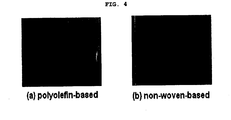
- a separator a p olyolefin-based or non-woven-based porous substrate having no color or a pale yellow color has been mainly used. There has been no case where a separator was used to identify the origin or kind of the separator itself or an electrochemical device.
- inorganic particle(s) having a unique spectrum or color pattern is(are) introduced into the separator according to a predetermined rule, so as to make the separator itself identifiable.
- Each kind of inorganic particle has its unique spectrum or color pattern. Therefore, when such inorganic particle(s) is(are) introduced into a separator according to a predetermined rule, the separator comprising the inorganic particle(s) can be identifiable like a trademark.
- the above “predetermined rule” means a specific spectrum (peak position and intensity) and/or color pattern determined preliminarily so that the separator can be distinguished from the others manufactured by a third party.
- the specific spectrum (peak position and intensity) and/or color pattern may be variable depending on the number, kind, content, etc. of the inorganic particles used in the separator. For example, it is possible to control the peak position and intensity by using one or more kinds of inorganic particles having a unique spectrum or color pattern and by adjusting the amounts of the particles.
- the color pattern by using one or more kinds of inorganic particles having a unique spectrum or color pattern in the visible light or non-visible light range; or one or more kinds of inorganic particles having a unique spectrum or color pattern under a specific chemical condition (e.g. temperature, oxidation state, etc.). Further, it is possible to control both the spectrum and the color pattern by using at least two kinds of the aforementioned inorganic particles in combination or by varying the arrangement of the particles.
- a specific chemical condition e.g. temperature, oxidation state, etc.
- the present invention it is possible to identify the origin or kind of the separator itself or the electrochemical device comprising the same by checking the spectrum and/or color pattern of the separator.
- the separator itself functions as a means for identification.
- the identification method according to the present invention may be applied to counterfeits made only inside the electrochemical device.
- the inorganic particle used in the present invention there is no particular limitation in the inorganic particle used in the present invention, as long as the particle has its unique spectrum or color pattern.
- the inorganic particle includes: (i) inorganic particles having a unique spectrum or color pattern in the visible light range; (ii) inorganic particles having a unique spectrum or color pattern in the non-visible light range; or (iii) inorganic particles having a unique spectrum or color pattern under a specific chemical condition (e.g. temperature or oxidation state).
- inorganic particles having a unique spectrum or color pattern through coloring belong to a scope of the present invention. In this case, the coloring may be achieved through a surface treatment by dye having a unique spectrum or color pattern.
- inorganic particles used in paints or pigments, or phosphor particles used in display devices or lamps may be used in the present invention.
- Non-limiting examples of the inorganic particle having a unique spectrum or color pattern such as a white, black, yellow, orange, brown, red, violet, blue, green, gray, pink or fluorescent color, in the visible light range (a wavelength range of 380 ⁇ 770nm) are as follows:
- the white inorganic particle(s) is(are) mixed with other inorganic particles, so as to diversely adjust the spectrum and/or the color patterns of the separator.
- the inorganic particle preferably has a size of 0.001 ⁇ m ⁇ 10 ⁇ m. If the size is less than 0.01 ⁇ m, the pores formed by the inorganic particles are too small. Thus, it may be difficult to function sufficiently as a separator. If the size is greater than 10 ⁇ m, the resultant separator has an increased thickness. Thus, it may result in an increase in the electrochemical device size or a decrease in the quantity of used electrode active material, thereby causing decrease in the capacity of the electrochemical.
- the inorganic particles may be connected and fixed to each other by polymers.
- binder polymers well-known in the art may be used.
- the polymer serves as a binder that interconnects and stably fixes the inorganic particles among themselves, and between the inorganic particles and the surface of an electrode substrate, and thus prevents degradation in mechanical properties of a resultant separator.
- the polymer preferably has a glass transition temperature (Tg) of between -200°C and 200°C in order to improve mechanical properties such as flexibility and elasticity of a final resultant separator.
- Tg glass transition temperature
- the polymer preferably shows a high degree of swelling with an electrolyte by being gelled when impregnated with an electrolyte, and more preferably has a solubility parameter between 15 and 45 MPa 1/2 . This is because, when the solubility parameter of the polymers is out of the above-mentioned range, it is difficult to swell the polymers with typical electrolyte for electrochemical devices.
- Non-limiting examples of the polymer that may be used in the present invention include polyvinylidene fluoride-co-hexafluoropropylene, polyvinylidene fluoride-co-trichloroethylene, polymethylmethacrylate, polyacrylonitrile, polyvinylpyrrolidone, polyvinylacetate, polyethylene-co-vinyl acetate, polyethylene oxide, cellulose acetate, cellulose acetate butyrate, cellulose acetate propionate, cyanoethylpullulan, cyanoethylpolyvinylalcohol, cyanoethylcellulose, cyanoethylsucrose, pullulan, carboxylmethyl cellulose, acrylonitrile-styrene-butadiene copolymer, polyimide or mixtures thereof.
- the ratio of the inorganic particles to the polymer when preparing the separator may be controlled in a range of 10:90 ⁇ 99:1 (on the weight basis), and preferably of 50:50 ⁇ 99:1 (on the weight basis), depending on the thickness and physical properties of the resultant separator and the content of the inorganic particles defined by the predetermined rule.
- the separator may further comprise other additives.
- the separator includes a porous structure formed due to the interstitial volume between the inorganic particles.
- the pores may be formed with a size of micrometer in a tangled configuration between inorganic particles; or between inorganic particles and polymers or between polymers in the case where the polymers are used.
- the porous structure can serve as a path for transfer and movement of lithium ions when filled with subsequently injected electrolyte. Therefore, the pore size and the porosity may significantly affect the adjustment of the ion conductivity of the separator.
- the pore size ranges from 0.001 to 10 ⁇ m and the porosity ranges from 5 to 95%, so as to have a sufficient room to be filled with the electrolyte and improve the lithium ion conductivity of the separator.
- the pore size and the porosity can be adjusted by the size of the inorganic particle, or by a content ratio (I/P) of the inorganic particle (I) to the polymers (P).
- the larger the inorganic particles are the larger the interstitial distance between the inorganic particles is and the larger the pore size is.
- the porosity may increase.
- separator thickness which can be adjusted within a range of 1 to 100 ⁇ m in consideration of the battery performance.
- the separator may be realized by two types of embodiments, but is not limited thereto.
- the inorganic particle containing layer is placed on at least one area selected from the group consisting of a surface of a porous substrate and a porous part of the substrate.
- the separator may have a structure including a porous substrate and inorganic particles coated on the substrate.
- porous substrate there is no particular limitation in the porous substrate, as long as it is a substrate having pores.
- a heat resistant porous substrate having a melting point of 200°C or higher is preferred.
- the heat-resistant porous substrate can improve the thermal stability of the separator and thus can prevent danger that may be caused by exterior and/or interior heat stimulation.
- Non-limiting examples of the porous substrate include high density polyethylene(HDPE), low density polyethylene(LDPE), linear low density polyethylene(LLDPE), ultra high molecular weight polyethylene(UHMW-PE), polyethylene terephthalate, polybutylene terephthalate, polyester, polyacetal, polyamide, polycarbonate, polyimide, polyetherether ketone, polyether sulfone, polyphenylene oxide, polyphenylene sulfidro, polyethylene naphthalene or mixtures thereof. Also, other heat resistant engineering plastics may be used with no particular limitation.
- HDPE high density polyethylene
- LDPE low density polyethylene
- LLDPE linear low density polyethylene
- UHMW-PE ultra high molecular weight polyethylene
- polyethylene terephthalate polybutylene terephthalate
- polyester polyacetal, polyamide, polycarbonate, polyimide, polyetherether ketone, polyether sulfone, polyphenylene oxide, polyphenylene s
- the porous substrate preferably has a thickness of between 1 ⁇ m and 100 ⁇ m, more preferably of between 5 ⁇ m and 50 ⁇ m.
- the porous substrate has a thickness of less than 1 ⁇ m, it is difficult to maintain mechanical properties.
- the porous substrate has a thickness of greater than 100 ⁇ m, it may function as resistance layer of lithium ion.
- the porous substrate preferably has a porosity of between 5% and 95%.
- the pore size (diameter) preferably ranges from 0.01 ⁇ m to 50 ⁇ m, more preferably from 0.1 ⁇ m to 20 ⁇ m.
- the porous substrate may function as resistance layer of lithium ion.
- the pore size and porosity are greater than 50 ⁇ m and 95%, respectively, it is difficult to maintain mechanical properties.
- the porous substrate may take the form of a membrane or fiber.
- the porous substrate may be a nonwoven web forming a porous web (preferably, spunbond type web comprising long fibers or melt blown type web).
- the separator may be manufactured by coating an inorganic particle(s) having a unique spectrum or color pattern on at least one area selected from the group consisting of a surface of the porous substrate and a porous part of the substrate.
- a specific pattern for example, stripes, dots, etc.
- One embodiment of the method for the above separator comprises the steps of: (i) manufacturing an inorganic particle solution by dissolving the inorganic particles into a solvent; and (ii) drying after coating the inorganic particle solution of step (i) on at least one area selected from the group consisting of a surface of a porous substrate and a porous part of the substrate.
- step (i) polymers capable of interconnecting and fixing the inorganic particles or other additives may be additionally used.
- the solvent preferably has a solubility parameter similar to that of the binder polymer to be used and a low boiling point, so as to facilitate uniform mixing and removal of the solvent.
- the solvent include acetone, tetrahydrofuran, methylene chloride, chloroform, dimethylformamide, N-methyl-2-pyrrolidone (NMP), cyclohexane, water or mixtures thereof.
- step (i) it is preferable to perform a step of pulverizing inorganic particles after dissolving the inorganic particles into the solvent.
- the time needed for pulverization is suitably 1-20 hours.
- the particle size of the pulverized particles ranges preferably from 0.001 and 10 ⁇ m. Conventional pulverization methods (ex. ball mill, attrition mill) may be used.
- step (ii) the conventional coating methods known to one skilled in the art may be used. It is possible to use various processes including dip coating, die coating, roll coating, comma coating or combinations thereof.
- a sputtering method preferably a sputtering method using a screen may be used. Then, it is possible to omit the step of dissolving inorganic particles into a solvent and removing the solvent. Thus, it is possible to form a pattern on the porous substrate easily and simply.
- Another feature employs a freestanding structure in which inorganic particles themselves can serve as supporters and spacers without a further supporter, such as the porous substrate. According to this feature, the inorganic particles are physically interconnected and fixed while forming a porous structure.
- the separator can be manufactured according to a process including the steps of: forming an inorganic particle-containing layer on a substrate (ex. Teflon sheet) according to the same method as in ⁇ separator example 1>; and then detaching the substrate or detaching the substrate and compressing.
- an electrochemical device may comprise an anode, a cathode, a separator, and an electrolyte.
- the separator includes the aforementioned separator.
- the electrochemical device includes all types of devices in which electrochemical reactions are performed.
- Particular examples of the electrochemical device include all types of primary batteries, secondary batteries, fuel cells, solar cells, or capacitors.
- the secondary batteries include lithium metal secondary batteries, lithium ion secondary batteries, lithium polymer secondary batteries or lithium ion polymer secondary batteries.
- the electrochemical device may be obtained by using a conventional method known to those skilled in the art, except that the separator is the aforementioned separator.
- the method may comprise the steps of: (a) inserting the aforementioned separator between the cathode and the anode to form an electrode assembly, and introducing the electrode assembly into a casing for an electrochemical device; and (b) injecting an electrolyte to the casing.
- the electrolyte may be used a conventional electrolyte known to those skilled in the art, and generally comprises an electrolyte salt and an electrolyte solvent.
- electrolyte salt there is no particular limitation in the electrolyte salt, as long as the salt is conventionally used as an electrolyte salt for a nonaqueous electrolyte.
- the electrolyte salt that may be used in the present invention includes a salt represented by the formula of A + B - , wherein A + represents an alkali metal cation selected from the group consisting of Li + , Na + , K + and combinations thereof, and B - represents an anion selected from the group consisting of PF 6 - , BF 4 - , Cl - , Br - , I - , ClO 4 - , AsF 6 - , CH 3 CO 3 - , N(CF 3 SO 2 ) 2 - , C(CF 2 SO 2 ) 3 - and combinations thereof.
- a lithium salt is particularly preferred.
- the electrolyte solvent that may be used in the present invention includes cyclic carbonates, linear carbonates, lactone, ether, ester, sulfoxide, acetonitrile, lactam, ketone, or the like.
- cyclic carbonates include ethylene carbonate (EC), propylene carbonate (PC), butylene carbonate (BC), fluoroethylene carbonate (FEC), or the like.
- linear carbonates include diethyl carbonate (DEC), dimethyl carbonate (DMC), dipropyl carbonate (DPC), ethyl methyl carbonate (EMC), methyl propyl carbonate (MPC), or the like.
- Non-limiting example of the lactone includes gamma-butyrolactone (GBL), and Non-limiting examples of the ether include dibutyl ether, tetrahydrofuran, 2-methyl tetrahydrofuran, 1,4-dioxane, diethoxy ethane, dimethoxy ethane, or the like.
- Non-limiting examples of the ester include methyl formate, ethyl formate, propyl formate, methyl acetate, ethyl acetate, propyl acetate, methyl propionate, ethyl propionate, propyl propionate, butyl propionate, methyl pivalate, or the like.
- example of the sulfoxide includes dimethyl sulfoxide and example of the ketone includes poly methyl vinyl ketone.
- Halogen derivatives of the above electrolyte solvents may also be used.
- the above electrolyte solvents may be used alone or in combination.
- the present invention provides a method for identifying the origin or kind of the separator itself or the electrochemical device comprising the same by using the aforementioned separator.
- the aforementioned separator comprises the inorganic particle(s) having a unique spectrum or color pattern according to a predetermined rule. Therefore, it is possible to identify the origin or kind of the separator itself or the electrochemical device comprising the same by using a sensor for observing a spectrum or color pattern (including the naked eye and a conventional spectrometer such as a visible light spectrometer) to check whether the spectrum or color pattern (e.g. color, brightness or saturation under a specific wavelength or chemical condition) of the inorganic particle(s) introduced into the separator conforms to the predetermined rule or not. In this manner, it is possible to identify the authenticity of the separator or electrochemical device according to the present invention. It is also possible to distinguish one type of separator or electrochemical device from the others. Therefore, any separator or electrochemical device can be prevented from being misused during a manufacturing process.
- a sensor for observing a spectrum or color pattern including the naked eye and a conventional spectrometer such as a visible light spectrometer
- PVdF-CTFE copolymer polyvinylidene fluoride-chlorotrifluoroethylene copolymer
- acetone a polyvinylidene fluoride-chlorotrifluoroethylene copolymer
- PVdF-CTFE polyvinylidene fluoride-chlorotrifluoroethylene copolymer
- a mixture containing inorganic particles showing a blue color in the visible light region, CoAl 2 O 4 , and PVdF-CTFE in a weight ratio of 80:20 was added, and then the inorganic particles were crushed and dispersed by using a ball mill for 12 hours or more to provide slurry.
- the inorganic particles had a particle diameter of 400 nm.
- NMP N-methyl-2-pyrrolidone
- 3 wt% of carbon black as a conductive agent 3 wt% of PVdF as a binder were added to form slurry for a cathode.
- the slurry was coated on Al foil having a thickness of about 20 ⁇ m as a cathode collector, and then dried to form a cathode. Then, the cathode was subjected to roll press.
- the cathode and anode obtained as described above were stacked with the separator as described in Example 1-1 to form an assembly. Then, an electrolyte was injected into the assembly to provide a secondary battery.
- the electrolyte contained 1M lithium hexafluorophosphate (LiPF 6 ) dissolved in ethylene carbonate (EC) and ethyl methyl carbonate (EMC) in a volume ratio of 1:2 (EC/EMC).
- a separator and a lithium secondary battery were provided in the same manner as described in Example 1, except that inorganic particles showing a green color in the visible light region, Cr 2 O 3 , were used instead of CoAl 2 O 4 .
- a separator and a lithium secondary battery were provided in the same manner as described in Example 1, except that inorganic particles showing a red color in the visible light region, Fe 2 O 3 , were used instead of CoAl 2 O 4 .
- a separator and a lithium secondary battery were provided in the same manner as described in Example 1, except that inorganic particles showing a yellow color in the visible light region, (Ti,Ni,Sb)O 2 , were used instead of CoAl 2 O 4 .
- a separator and a lithium secondary battery were provided in the same manner as described in Example 1, except that inorganic particles containing CoAl 2 O 4 and Fe 2 O 3 in a weight ratio of 33:67 were used instead of CoAl 2 O 4 .
- a separator and a lithium secondary battery were provided in the same manner as described in Example 1, except that inorganic particles containing CoAl 2 O 4 and Fe 2 O 3 in a weight ratio of 67:33 were used instead of CoAl 2 O 4 .
- a separator and a lithium secondary battery were manufactured in the same manner as in Example 1, except that Cr 2 O 3 and Al 2 O 3 were used instead of CoAl 2 O 4 and the weight ratio of Cr 2 O 3 : Al 2 O 3 : PVdF was changed to 60:20:20, 30:50:20, and 10:70:20.
- a separator and a lithium secondary battery were provided in the same manner as described in Example 1, except that SiC was used instead of CoAl 2 O 4 .
- a separator and a lithium secondary battery were provided in the same manner as described in Example 1, except that inorganic particles showing a white color in the visible light region, alumina (Al 2 O 3 ), were used instead of CoAl 2 O 4 .
- FIGs. 1 , 2 , 3 and 4 show the photographic views of the separators according to Examples 1 ⁇ 8 and polyolefin-based separator, taken in the visible light range. It can be seen from the above results that the separator can be identified sufficiently with the naked eye.
- the present invention it is possible to identify the origin or kind of the separator itself or the electrochemical device using the same separator without any modification or addition in the structure of the device. Thus, it is possible to identify the authenticity of the separator or electrochemical device according to the present invention. It is also possible to distinguish one type of separator or electrochemical device from the others. Therefore, any separator or electrochemical device can be prevented from being misused during a manufacturing process.
Description
- The present invention relates to a method for identifying the origin or kind of a separator that allows users to easily identify the origin or kind of the separator itself or an electrochemical device using the same separator.
- Electrochemical devices are power sources for electronic appliances, etc. As the use of batteries is enlarged to applications for the storage of energy for portable telephones, camcorders, notebook computers, personal computers and electric vehicles, efforts on the research and development of batteries are increasingly embodied.
- Meanwhile, since the electrochemical devices have been in increasing demand, counterfeits thereof have been distributed more and more. Such counterfeits have much lower safety than authentic products. Therefore, there has been an imminent need for a method for checking the authenticity of an electrochemical device.
- According to the prior art, there has been suggested a method for checking the authenticity of an electrochemical device by incorporating a semiconductor capable of communicating with the main body of an electronic appliance into the electrochemical device. However, the above method requires an additional space for housing the semiconductor inside the device, so that the space for receiving electrodes inside the device grows smaller. This ultimately results in a drop in the capacity of a battery. Additionally, such introduction of a semiconductor into the electrochemical device causes degradation of the productivity and cost-efficiency.
-
WO 2006/068428 A1 discloses a separator including inorganic particles and a lithium secondary battery comprising the same. - Therefore, the present invention has been made in view of the above-mentioned problems. It is an object of the present invention to provide a method for identifying the origin or kind of a separator which inorganic particle(s) having a unique spectrum or color pattern is(are) introduced according to a predetermined rule, so that the separator is identifiable and the separator or an electrochemical device using the same allows users to identify its origin or kind.
- In order to achieve the above-mentioned object, there is provided a method for identifying the origin or kind of the separator itself or the electrochemical device comprising the same by using a separator.
- An electrochemical device includes an anode, a cathode, a separator, and an electrolyte. Herein, the separator can prevent electric contact of the anode and the cathode while allowing ions to pass through the separator. As a separator a polyolefin-based or non-woven-based porous substrate having no color or a pale yellow color has been mainly used. There has been no case where a separator was used to identify the origin or kind of the separator itself or an electrochemical device.
- According to the present invention, inorganic particle(s) having a unique spectrum or color pattern is(are) introduced into the separator according to a predetermined rule, so as to make the separator itself identifiable.
- Each kind of inorganic particle has its unique spectrum or color pattern. Therefore, when such inorganic particle(s) is(are) introduced into a separator according to a predetermined rule, the separator comprising the inorganic particle(s) can be identifiable like a trademark.
- Herein, the above "predetermined rule" means a specific spectrum (peak position and intensity) and/or color pattern determined preliminarily so that the separator can be distinguished from the others manufactured by a third party. Particularly, the specific spectrum (peak position and intensity) and/or color pattern may be variable depending on the number, kind, content, etc. of the inorganic particles used in the separator. For example, it is possible to control the peak position and intensity by using one or more kinds of inorganic particles having a unique spectrum or color pattern and by adjusting the amounts of the particles. Otherwise, it is possible to control the color pattern by using one or more kinds of inorganic particles having a unique spectrum or color pattern in the visible light or non-visible light range; or one or more kinds of inorganic particles having a unique spectrum or color pattern under a specific chemical condition (e.g. temperature, oxidation state, etc.). Further, it is possible to control both the spectrum and the color pattern by using at least two kinds of the aforementioned inorganic particles in combination or by varying the arrangement of the particles.
- Therefore, according to the present invention, it is possible to identify the origin or kind of the separator itself or the electrochemical device comprising the same by checking the spectrum and/or color pattern of the separator. Particularly, according to the present invention, the separator itself functions as a means for identification. Thus, no additional space for an identification means is required, thereby preventing a drop in the capacity of the electrochemical device. Also, the identification method according to the present invention may be applied to counterfeits made only inside the electrochemical device.
- There is no particular limitation in the inorganic particle used in the present invention, as long as the particle has its unique spectrum or color pattern.
- For example, the inorganic particle includes: (i) inorganic particles having a unique spectrum or color pattern in the visible light range; (ii) inorganic particles having a unique spectrum or color pattern in the non-visible light range; or (iii) inorganic particles having a unique spectrum or color pattern under a specific chemical condition (e.g. temperature or oxidation state). In addition, inorganic particles having a unique spectrum or color pattern through coloring belong to a scope of the present invention. In this case, the coloring may be achieved through a surface treatment by dye having a unique spectrum or color pattern. Also, inorganic particles used in paints or pigments, or phosphor particles used in display devices or lamps may be used in the present invention.
- Non-limiting examples of the inorganic particle having a unique spectrum or color pattern, such as a white, black, yellow, orange, brown, red, violet, blue, green, gray, pink or fluorescent color, in the visible light range (a wavelength range of 380∼770nm) are as follows:
- (a) white: Al2O3, ZnO, ZnS, SiO2, ZrO2, SnO2, CeO2, MgO, CaO, Y2O3, TiO2, Sb2O3, BaTiO3, SrTiO3, Pb(Zr,Ti)O3 (PZT), Pb1-xLaxZr1-yTiyO3 (PLZT), etc.
- (b) black: Fe3O4, (Co, Ni)O-(Cr, Fe)2O3, etc.
- (c) yellow: PbCrO4, ZnCr04, BaCrO4, CdS, FeO(OH) nH2O, TiO2-NiO-Sb2O3, Pb(CN)2, Ca2PbO4, Al,Fe,Sn-2PbO-Sb2O5, V-SnO2, V-ZrO2, Pr-ZrSiO4, CrSbO4 or Cr2WO6-TiO2, ZrSO4 coated CdS or (CdZn)S, etc.
- (d) orange: PbCrO4 PbO, PbCrO4 PbMoO4 PbSO4, etc.
- (e) brown: Fe2O3+FeO, Fe2O3+MnO2+Mn3O4, ZnO ·(Al, Cr, Fe)2O3, etc.
- (f) red: Fe2O3, Pb3O4, HgS, CdS+CdSe, CdS+HgS, 2Sb2S3 Sb2O3, etc.
- (g) violet: Co3(PO4)2, Co3(PO4)2 4H2O, Co3(PO4)2 8H2O, etc.
- (h) blue: 3NaAl SiO4 Na2S2, Fe4[Fe(CN6)3] nH2O, CoO nAl2O3, CoO nSnO2 mMgO(n=1.5∼3.5, m=2∼6), Co3O4+SiO2+Al2O3+Fe2O3+NiO+MnO, CoO-nAl2O3 or (Co, Zn)O-nAl2O3, 2(Co, Zn)O ·SiO2, V-ZrSiO4, etc.
- (i) green: Cr2O3, Cr2O(OH)4, Cu(CH3CO2)2 3CuO(AsO2)2, CoO-ZnO-MgO, (Co, Zn)O ·(Al, Cr)2O3, 3CaO-Cr2O3 ·3SiO2, (Al, Cr)2O3, etc.
- (j) gray: Sb-SnO2, Co, Ni-ZrSiO4, etc.
- (k) pink: Mn, P-α-Al2O3, ZnO ·(Al, Cr)2O3, Cr-CaO ·SnO2 ·SiO2, Fe-ZrSiO4, Cr,Co-CaO ·SnO2 ·SiO2, ZrSiO4 coated Cd(S,Se), etc.
- (l) fluorescent color: ZnS, Zn2SiO4, (Zn,Cd)S, CaS, SrS, CaWO4, etc.
- (m) others: SiC (green and/or black), Si3N4(white), etc.
- In this case, it is preferred that the white inorganic particle(s) is(are) mixed with other inorganic particles, so as to diversely adjust the spectrum and/or the color patterns of the separator.
- Although there is no particular limitation in the size of the inorganic particle, the inorganic particle preferably has a size of 0.001 µm∼10 µm. If the size is less than 0.01 µm, the pores formed by the inorganic particles are too small. Thus, it may be difficult to function sufficiently as a separator. If the size is greater than 10 µm, the resultant separator has an increased thickness. Thus, it may result in an increase in the electrochemical device size or a decrease in the quantity of used electrode active material, thereby causing decrease in the capacity of the electrochemical.
- Meanwhile, the inorganic particles may be connected and fixed to each other by polymers. Herein, for the polymer, binder polymers well-known in the art may be used. The polymer serves as a binder that interconnects and stably fixes the inorganic particles among themselves, and between the inorganic particles and the surface of an electrode substrate, and thus prevents degradation in mechanical properties of a resultant separator.
- The polymer preferably has a glass transition temperature (Tg) of between -200°C and 200°C in order to improve mechanical properties such as flexibility and elasticity of a final resultant separator.
- Additionally, the polymer preferably shows a high degree of swelling with an electrolyte by being gelled when impregnated with an electrolyte, and more preferably has a solubility parameter between 15 and 45 MPa1/2. This is because, when the solubility parameter of the polymers is out of the above-mentioned range, it is difficult to swell the polymers with typical electrolyte for electrochemical devices.
- Non-limiting examples of the polymer that may be used in the present invention include polyvinylidene fluoride-co-hexafluoropropylene, polyvinylidene fluoride-co-trichloroethylene, polymethylmethacrylate, polyacrylonitrile, polyvinylpyrrolidone, polyvinylacetate, polyethylene-co-vinyl acetate, polyethylene oxide, cellulose acetate, cellulose acetate butyrate, cellulose acetate propionate, cyanoethylpullulan, cyanoethylpolyvinylalcohol, cyanoethylcellulose, cyanoethylsucrose, pullulan, carboxylmethyl cellulose, acrylonitrile-styrene-butadiene copolymer, polyimide or mixtures thereof.
- There is no particular limitation in the ratio of the inorganic particles to the polymer when preparing the separator. The ratio may be controlled in a range of 10:90∼99:1 (on the weight basis), and preferably of 50:50∼99:1 (on the weight basis), depending on the thickness and physical properties of the resultant separator and the content of the inorganic particles defined by the predetermined rule.
- The separator may further comprise other additives.
- Meanwhile, the separator includes a porous structure formed due to the interstitial volume between the inorganic particles. Herein, the pores may be formed with a size of micrometer in a tangled configuration between inorganic particles; or between inorganic particles and polymers or between polymers in the case where the polymers are used. The porous structure can serve as a path for transfer and movement of lithium ions when filled with subsequently injected electrolyte. Therefore, the pore size and the porosity may significantly affect the adjustment of the ion conductivity of the separator. For this reason, preferably, the pore size ranges from 0.001 to 10µm and the porosity ranges from 5 to 95%, so as to have a sufficient room to be filled with the electrolyte and improve the lithium ion conductivity of the separator. In this case, the pore size and the porosity can be adjusted by the size of the inorganic particle, or by a content ratio (I/P) of the inorganic particle (I) to the polymers (P). For example, the larger the inorganic particles are, the larger the interstitial distance between the inorganic particles is and the larger the pore size is. Moreover, as the content ratio (I/P) of the inorganic particle (I) to the polymers (p) grows higher, the porosity may increase.
- Also, there is no particular limitation in the separator thickness, which can be adjusted within a range of 1 to 100µm in consideration of the battery performance.
- The separator may be realized by two types of embodiments, but is not limited thereto.
- According to one embodiment of the separator, the inorganic particle containing layer is placed on at least one area selected from the group consisting of a surface of a porous substrate and a porous part of the substrate. For example, the separator may have a structure including a porous substrate and inorganic particles coated on the substrate.
- There is no particular limitation in the porous substrate, as long as it is a substrate having pores. However, a heat resistant porous substrate having a melting point of 200°C or higher is preferred.
- This is because the heat-resistant porous substrate can improve the thermal stability of the separator and thus can prevent danger that may be caused by exterior and/or interior heat stimulation.
- Non-limiting examples of the porous substrate include high density polyethylene(HDPE), low density polyethylene(LDPE), linear low density polyethylene(LLDPE), ultra high molecular weight polyethylene(UHMW-PE), polyethylene terephthalate, polybutylene terephthalate, polyester, polyacetal, polyamide, polycarbonate, polyimide, polyetherether ketone, polyether sulfone, polyphenylene oxide, polyphenylene sulfidro, polyethylene naphthalene or mixtures thereof. Also, other heat resistant engineering plastics may be used with no particular limitation.
- Although there is no particular limitation in thickness of the porous substrate, the porous substrate preferably has a thickness of between 1 µm and 100 µm, more preferably of between 5 µm and 50 µm. When the porous substrate has a thickness of less than 1 µm, it is difficult to maintain mechanical properties. When the porous substrate has a thickness of greater than 100 µm, it may function as resistance layer of lithium ion.
- Although there is no particular limitation in pore size and porosity of the porous substrate, the porous substrate preferably has a porosity of between 5% and 95%. The pore size (diameter) preferably ranges from 0.01 µm to 50 µm, more preferably from 0.1 µm to 20 µm. When the pore size and porosity are less than 0.01 µm and 5%, respectively, the porous substrate may function as resistance layer of lithium ion. When the pore size and porosity are greater than 50 µm and 95%, respectively, it is difficult to maintain mechanical properties.
- The porous substrate may take the form of a membrane or fiber. When the porous substrate is fibrous, it may be a nonwoven web forming a porous web (preferably, spunbond type web comprising long fibers or melt blown type web).
- The separator may be manufactured by coating an inorganic particle(s) having a unique spectrum or color pattern on at least one area selected from the group consisting of a surface of the porous substrate and a porous part of the substrate. In this case, it is preferred to form a specific pattern (for example, stripes, dots, etc.) on the porous substrate, by coating the inorganic particle(s) on the entire surface, a portion of the surface, or a portion of the porous part of the porous substrate.
- One embodiment of the method for the above separator comprises the steps of: (i) manufacturing an inorganic particle solution by dissolving the inorganic particles into a solvent; and (ii) drying after coating the inorganic particle solution of step (i) on at least one area selected from the group consisting of a surface of a porous substrate and a porous part of the substrate.
- In this case, in step (i), polymers capable of interconnecting and fixing the inorganic particles or other additives may be additionally used.
- Meanwhile, in step (i), although there is no particular limitation in the solvent, the solvent preferably has a solubility parameter similar to that of the binder polymer to be used and a low boiling point, so as to facilitate uniform mixing and removal of the solvent. Non-limiting examples of the solvent that may be used include acetone, tetrahydrofuran, methylene chloride, chloroform, dimethylformamide, N-methyl-2-pyrrolidone (NMP), cyclohexane, water or mixtures thereof.
- Also, in step (i), it is preferable to perform a step of pulverizing inorganic particles after dissolving the inorganic particles into the solvent. The time needed for pulverization is suitably 1-20 hours. The particle size of the pulverized particles ranges preferably from 0.001 and 10 µm. Conventional pulverization methods (ex. ball mill, attrition mill) may be used.
- And, in step (ii), the conventional coating methods known to one skilled in the art may be used. It is possible to use various processes including dip coating, die coating, roll coating, comma coating or combinations thereof.
- Meanwhile, in order to coat the inorganic particles on the porous substrate, a sputtering method, preferably a sputtering method using a screen may be used. Then, it is possible to omit the step of dissolving inorganic particles into a solvent and removing the solvent. Thus, it is possible to form a pattern on the porous substrate easily and simply.
- Another feature employs a freestanding structure in which inorganic particles themselves can serve as supporters and spacers without a further supporter, such as the porous substrate. According to this feature, the inorganic particles are physically interconnected and fixed while forming a porous structure.
- The separator can be manufactured according to a process including the steps of: forming an inorganic particle-containing layer on a substrate (ex. Teflon sheet) according to the same method as in <separator example 1>; and then detaching the substrate or detaching the substrate and compressing.
- Furthermore, an electrochemical device may comprise an anode, a cathode, a separator, and an electrolyte. In this case, the separator includes the aforementioned separator.
- The electrochemical device includes all types of devices in which electrochemical reactions are performed. Particular examples of the electrochemical device include all types of primary batteries, secondary batteries, fuel cells, solar cells, or capacitors. Examples of the secondary batteries include lithium metal secondary batteries, lithium ion secondary batteries, lithium polymer secondary batteries or lithium ion polymer secondary batteries.
- The electrochemical device may be obtained by using a conventional method known to those skilled in the art, except that the separator is the aforementioned separator. For example, the method may comprise the steps of: (a) inserting the aforementioned separator between the cathode and the anode to form an electrode assembly, and introducing the electrode assembly into a casing for an electrochemical device; and (b) injecting an electrolyte to the casing.
- The electrolyte may be used a conventional electrolyte known to those skilled in the art, and generally comprises an electrolyte salt and an electrolyte solvent. There is no particular limitation in the electrolyte salt, as long as the salt is conventionally used as an electrolyte salt for a nonaqueous electrolyte.
- The electrolyte salt that may be used in the present invention includes a salt represented by the formula of A+B-, wherein A+ represents an alkali metal cation selected from the group consisting of Li+, Na+, K+ and combinations thereof, and B- represents an anion selected from the group consisting of PF6 -, BF4 -, Cl-, Br-, I-, ClO4 -, AsF6 -, CH3CO3 -, N(CF3SO2)2 -, C(CF2SO2)3 - and combinations thereof. A lithium salt is particularly preferred.
- The electrolyte solvent that may be used in the present invention includes cyclic carbonates, linear carbonates, lactone, ether, ester, sulfoxide, acetonitrile, lactam, ketone, or the like. Non-limiting examples of the cyclic carbonates include ethylene carbonate (EC), propylene carbonate (PC), butylene carbonate (BC), fluoroethylene carbonate (FEC), or the like. Non-limiting examples of the linear carbonates include diethyl carbonate (DEC), dimethyl carbonate (DMC), dipropyl carbonate (DPC), ethyl methyl carbonate (EMC), methyl propyl carbonate (MPC), or the like. Non-limiting example of the lactone includes gamma-butyrolactone (GBL), and Non-limiting examples of the ether include dibutyl ether, tetrahydrofuran, 2-methyl tetrahydrofuran, 1,4-dioxane, diethoxy ethane, dimethoxy ethane, or the like. Non-limiting examples of the ester include methyl formate, ethyl formate, propyl formate, methyl acetate, ethyl acetate, propyl acetate, methyl propionate, ethyl propionate, propyl propionate, butyl propionate, methyl pivalate, or the like. Also, example of the sulfoxide includes dimethyl sulfoxide and example of the ketone includes poly methyl vinyl ketone. Halogen derivatives of the above electrolyte solvents may also be used. The above electrolyte solvents may be used alone or in combination.
- The present invention provides a method for identifying the origin or kind of the separator itself or the electrochemical device comprising the same by using the aforementioned separator.
- The aforementioned separator comprises the inorganic particle(s) having a unique spectrum or color pattern according to a predetermined rule. Therefore, it is possible to identify the origin or kind of the separator itself or the electrochemical device comprising the same by using a sensor for observing a spectrum or color pattern (including the naked eye and a conventional spectrometer such as a visible light spectrometer) to check whether the spectrum or color pattern (e.g. color, brightness or saturation under a specific wavelength or chemical condition) of the inorganic particle(s) introduced into the separator conforms to the predetermined rule or not. In this manner, it is possible to identify the authenticity of the separator or electrochemical device according to the present invention. It is also possible to distinguish one type of separator or electrochemical device from the others. Therefore, any separator or electrochemical device can be prevented from being misused during a manufacturing process.
-
-
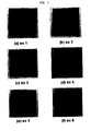
FIG. 1 is photographs of separators manufactured according to Examples 1-6. -
FIG. 2 is photographs of separators manufactured according to Examples of 2 and 7. -
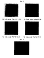
FIG. 3 is a photograph of a separator manufactured according to Example 8. -
FIG. 4 is photographs of a polyolefin-based separator; and a non-woven -based separator. -
FIG. 5 is the absorption spectra of the separators according to Examples 1∼6 and Comparative Example 1. - Reference will now be made in detail to the preferred embodiments of the present invention.
- About 5 parts by weight of a polyvinylidene fluoride-chlorotrifluoroethylene copolymer (PVdF-CTFE copolymer) was added to 100 parts by weight of acetone and dissolved therein at 50°C for about 12 hours or more to provide a polymer solution. To the preformed polymer solution, a mixture containing inorganic particles showing a blue color in the visible light region, CoAl2O4, and PVdF-CTFE in a weight ratio of 80:20 was added, and then the inorganic particles were crushed and dispersed by using a ball mill for 12 hours or more to provide slurry. In the slurry, the inorganic particles had a particle diameter of 400 nm.
- Then, the slurry was coated onto the surface of the cathode and the anode obtained as described above via a dip coating process, followed by drying, to provide a separator. 1-2. Manufacture of Lithium Secondary Battery
- To N-methyl-2-pyrrolidone (NMP) as a solvent, 94 wt% of LiCoO2 as a cathode active material, 3 wt% of carbon black as a conductive agent and 3 wt% of PVdF as a binder were added to form slurry for a cathode. The slurry was coated on Al foil having a thickness of about 20 µm as a cathode collector, and then dried to form a cathode. Then, the cathode was subjected to roll press.
- To NMP as a solvent, 96 wt% of carbon powder as an anode active material, 3 wt% of polyvinylidene fluoride (PVdF) as a binder and 1 wt% of carbon black as a conductive agent were added to form mixed slurry for an anode. The slurry was coated on Cu foil having a thickness of about 10 µm as an anode collector, and then dried to form an anode. Then, the anode was subjected to roll press.
- The cathode and anode obtained as described above were stacked with the separator as described in Example 1-1 to form an assembly. Then, an electrolyte was injected into the assembly to provide a secondary battery. The electrolyte contained 1M lithium hexafluorophosphate (LiPF6) dissolved in ethylene carbonate (EC) and ethyl methyl carbonate (EMC) in a volume ratio of 1:2 (EC/EMC).
- A separator and a lithium secondary battery were provided in the same manner as described in Example 1, except that inorganic particles showing a green color in the visible light region, Cr2O3, were used instead of CoAl2O4.
- A separator and a lithium secondary battery were provided in the same manner as described in Example 1, except that inorganic particles showing a red color in the visible light region, Fe2O3, were used instead of CoAl2O4.
- A separator and a lithium secondary battery were provided in the same manner as described in Example 1, except that inorganic particles showing a yellow color in the visible light region, (Ti,Ni,Sb)O2, were used instead of CoAl2O4.
- A separator and a lithium secondary battery were provided in the same manner as described in Example 1, except that inorganic particles containing CoAl2O4 and Fe2O3 in a weight ratio of 33:67 were used instead of CoAl2O4.
- A separator and a lithium secondary battery were provided in the same manner as described in Example 1, except that inorganic particles containing CoAl2O4 and Fe2O3 in a weight ratio of 67:33 were used instead of CoAl2O4.
- A separator and a lithium secondary battery were manufactured in the same manner as in Example 1, except that Cr2O3 and Al2O3 were used instead of CoAl2O4 and the weight ratio of Cr2O3: Al2O3: PVdF was changed to 60:20:20, 30:50:20, and 10:70:20.
- A separator and a lithium secondary battery were provided in the same manner as described in Example 1, except that SiC was used instead of CoAl2O4.
- A separator and a lithium secondary battery were provided in the same manner as described in Example 1, except that inorganic particles showing a white color in the visible light region, alumina (Al2O3), were used instead of CoAl2O4.
- The absorption spectra of the separators according to Examples 1∼6 and Comparative Example 1 were observed by using a spectrometer. The results are shown in
FIG. 5 . It can be seen from the experimental results that the separator introduced the inorganic particle(s) shows a different spectrum depending on the kind and content of the inorganic particle(s). Such a specific spectrum can function as a means for identifying the separator itself or the electrochemical device using the same. - Meanwhile,
FIGs. 1 ,2 ,3 and4 show the photographic views of the separators according to Examples 1∼8 and polyolefin-based separator, taken in the visible light range. It can be seen from the above results that the separator can be identified sufficiently with the naked eye. - As can be seen from the foregoing, according to the present invention, it is possible to identify the origin or kind of the separator itself or the electrochemical device using the same separator without any modification or addition in the structure of the device. Thus, it is possible to identify the authenticity of the separator or electrochemical device according to the present invention. It is also possible to distinguish one type of separator or electrochemical device from the others. Therefore, any separator or electrochemical device can be prevented from being misused during a manufacturing process.
Claims (1)
- A method for identifying the origin or kind of a separator itself or an electrochemical device having the separator, the method comprising:observing a spectrum of inorganic particles or aggregates included in the separator by utilizing a sensor for observing a spectrum, wherein the spectrum of inorganic particles or aggregates included in the separator is determined preliminarily according to a predetermined rule so that the separator is distinguished from the others manufactured by a third party; andchecking whether the observed spectrum conforms to the predetermined rule.
Applications Claiming Priority (2)
| Application Number | Priority Date | Filing Date | Title |
|---|---|---|---|
| KR20060093057 | 2006-09-25 | ||
| PCT/KR2007/004665 WO2008038971A1 (en) | 2006-09-25 | 2007-09-21 | Novel separator and electrochemical device comprising the same |
Publications (3)
| Publication Number | Publication Date |
|---|---|
| EP2070137A1 EP2070137A1 (en) | 2009-06-17 |
| EP2070137A4 EP2070137A4 (en) | 2013-07-31 |
| EP2070137B1 true EP2070137B1 (en) | 2014-10-29 |
Family
ID=39230356
Family Applications (1)
| Application Number | Title | Priority Date | Filing Date |
|---|---|---|---|
| EP07808432.4A Active EP2070137B1 (en) | 2006-09-25 | 2007-09-21 | Method for identifying the origin or kind of a separator itself or of an electrochemical device having the separator |
Country Status (6)
| Country | Link |
|---|---|
| US (1) | US8062795B2 (en) |
| EP (1) | EP2070137B1 (en) |
| JP (1) | JP5189099B2 (en) |
| KR (1) | KR100941264B1 (en) |
| CN (1) | CN101517783B (en) |
| WO (1) | WO2008038971A1 (en) |
Families Citing this family (21)
| Publication number | Priority date | Publication date | Assignee | Title |
|---|---|---|---|---|
| KR100995074B1 (en) * | 2007-12-11 | 2010-11-18 | 삼성에스디아이 주식회사 | Separator for non-aqueous lithium secondary battery and non-aqueous lithium secondary battery comprising the same |
| CN102132452A (en) * | 2008-08-25 | 2011-07-20 | 株式会社Lg化学 | Separator furnished with porous coating layer, method of manufacturing same, and electrochemical device furnished therewith |
| US20100062342A1 (en) * | 2008-09-09 | 2010-03-11 | Lin-Feng Li | Polymer membrane utilized as a separator in rechargeable zinc cells |
| US9356273B2 (en) * | 2009-12-04 | 2016-05-31 | Sony Corporation | Nonaqueous electrolyte secondary battery and separator |
| WO2013094004A1 (en) * | 2011-12-19 | 2013-06-27 | トヨタ自動車株式会社 | Lithium secondary battery |
| US9093710B2 (en) * | 2012-01-18 | 2015-07-28 | E I Du Pont De Nemours And Company | Compositions, layerings, electrodes and methods for making |
| DE102012004161A1 (en) | 2012-03-05 | 2013-09-05 | Treofan Germany Gmbh & Co. Kg | Highly porous separator film with partial coating |
| KR101705304B1 (en) * | 2012-11-30 | 2017-02-09 | 주식회사 엘지화학 | A separator, the manufacturing method thereof, and elecrochemical device containing the same |
| US10454088B2 (en) | 2012-12-27 | 2019-10-22 | 3M Innovative Properties Company | Electrochemical device and method of making the same |
| CN103633269A (en) * | 2013-08-22 | 2014-03-12 | 东莞市易威科电子科技有限公司 | Yellow ceramic diaphragm for lithium ion battery and application thereof |
| US20150072594A1 (en) * | 2013-09-09 | 2015-03-12 | Apple Inc. | Method for detecting a polishing compound and related system and computer program product |
| KR101536560B1 (en) * | 2014-12-30 | 2015-07-15 | 한밭대학교 산학협력단 | Patterned Ceramic Coated Separator, Method for Manufacturing Same, and Secondary battery |
| US10637063B2 (en) * | 2015-12-25 | 2020-04-28 | Zeon Corporation | Binder composition for non-aqueous secondary battery porous membrane, slurry composition for non-aqueous secondary battery porous membrane, porous membrane for non-aqueous secondary battery, and non-aqueous secondary battery |
| CN106282949A (en) * | 2016-08-04 | 2017-01-04 | 深圳市第四能源科技有限公司 | A kind of method preparing ceramic membrane at lithium battery non-woven fabrics membrane surface |
| JP7020268B2 (en) * | 2018-04-23 | 2022-02-16 | トヨタ自動車株式会社 | Fuel cell separator |
| CN108711603A (en) * | 2018-04-27 | 2018-10-26 | 青岛蓝科途膜材料有限公司 | Coloured ceramic coated film of a kind of aramid fiber polymeric compound coating and preparation method thereof |
| CN108963158B (en) * | 2018-07-10 | 2021-10-22 | 福建师范大学 | Preparation method of polymer coating film containing P-O bond compound |
| KR20200098860A (en) * | 2019-02-13 | 2020-08-21 | 주식회사 엘지화학 | Cathode for lithium secondary battery comprising goethite, and lithium secondary battery comprising the same |
| KR102594367B1 (en) * | 2019-04-16 | 2023-10-27 | 주식회사 엘지에너지솔루션 | Electrode assembly comprising coated part with different color and method for preparing the same |
| CN113328204A (en) * | 2021-04-20 | 2021-08-31 | 惠州锂威电子科技有限公司 | Lithium ion battery isolating membrane and preparation method thereof |
| CN115224436B (en) * | 2022-07-20 | 2023-08-01 | 惠州锂威新能源科技有限公司 | Preparation method of lithium ion battery diaphragm |
Family Cites Families (28)
| Publication number | Priority date | Publication date | Assignee | Title |
|---|---|---|---|---|
| JP2761301B2 (en) * | 1991-02-25 | 1998-06-04 | 新神戸電機株式会社 | Electrolyte holder |
| US5298346A (en) * | 1992-07-27 | 1994-03-29 | Motorola, Inc. | Battery identification system |
| US5336573A (en) * | 1993-07-20 | 1994-08-09 | W. R. Grace & Co.-Conn. | Battery separator |
| CA2226366C (en) * | 1995-08-28 | 2002-05-21 | Asahi Kasei Kogyo Kabushiki Kaisha | Novel battery and method for producing the same |
| JPH1064525A (en) | 1996-08-22 | 1998-03-06 | Dainippon Printing Co Ltd | Electrode plate for nonaqueous electrolyte secondary battery and manufacture thereof |
| US5882721A (en) * | 1997-05-01 | 1999-03-16 | Imra America Inc | Process of manufacturing porous separator for electrochemical power supply |
| JP3175730B2 (en) * | 1998-04-27 | 2001-06-11 | 住友化学工業株式会社 | Non-aqueous electrolyte battery separator and lithium secondary battery |
| US20020132107A1 (en) * | 1998-05-15 | 2002-09-19 | O'brien Jeffrey James | Porous polyethylene membrane |
| KR20000019372A (en) | 1998-09-10 | 2000-04-06 | 박호군 | Solid polymer alloy electrolyte of homogeneous phase, complex electrode using the electrolyte, lithium polymer battery, lithium ion polymer battery and manufacturing method thereof |
| US6194098B1 (en) * | 1998-12-17 | 2001-02-27 | Moltech Corporation | Protective coating for separators for electrochemical cells |
| JP2001250529A (en) * | 2000-03-03 | 2001-09-14 | Nippon Sheet Glass Co Ltd | Alkaline secondary battery |
| US6432586B1 (en) | 2000-04-10 | 2002-08-13 | Celgard Inc. | Separator for a high energy rechargeable lithium battery |
| JP2001307778A (en) * | 2000-04-21 | 2001-11-02 | Sony Corp | Device and method for carrying battery material |
| AU2001246908B2 (en) * | 2000-05-22 | 2004-05-06 | Asahi Kasei Kabushiki Kaisha | Separator for zinc bromine secondary cell and method for its preparation |
| JP2002008618A (en) * | 2000-06-26 | 2002-01-11 | Nippon Muki Co Ltd | Separator for lead-acid battery |
| KR100406690B1 (en) | 2001-03-05 | 2003-11-21 | 주식회사 엘지화학 | Electrochemical device using multicomponent composite membrane film |
| KR100433002B1 (en) * | 2001-12-07 | 2004-05-24 | 삼성에스디아이 주식회사 | Electrode, lithium battery adopting the same, and method for manufacturing the same |
| DE10255121B4 (en) * | 2002-11-26 | 2017-09-14 | Evonik Degussa Gmbh | Separator with asymmetric pore structure for an electrochemical cell |
| JP4107151B2 (en) * | 2003-05-06 | 2008-06-25 | ソニー株式会社 | Battery identifier, battery and battery pack |
| JP2005100833A (en) * | 2003-09-25 | 2005-04-14 | Sony Corp | Secondary battery and its manufacturing method |
| KR20050093018A (en) * | 2004-03-18 | 2005-09-23 | 한국과학기술연구원 | Efficient 3-d nanostructured membranes |
| JP2005276503A (en) * | 2004-03-23 | 2005-10-06 | Mitsubishi Electric Corp | Separator for battery and battery using the same |
| KR100601562B1 (en) | 2004-07-29 | 2006-07-19 | 삼성에스디아이 주식회사 | Electrode assembly and Lithium secondary battery with the same |
| KR100601530B1 (en) | 2004-09-09 | 2006-07-19 | 삼성에스디아이 주식회사 | Lithium Ion Secondary Battery |
| JP4827117B2 (en) * | 2004-11-11 | 2011-11-30 | 日立マクセルエナジー株式会社 | Nonaqueous battery and manufacturing method thereof |
| JP4743747B2 (en) * | 2004-12-08 | 2011-08-10 | 日立マクセル株式会社 | Separator, manufacturing method thereof, and nonaqueous electrolyte battery |
| KR100775310B1 (en) | 2004-12-22 | 2007-11-08 | 주식회사 엘지화학 | Organic/inorganic composite microporous membrane and electrochemical device prepared thereby |
| KR100903502B1 (en) * | 2006-07-19 | 2009-06-17 | 주식회사 엘지화학 | Electrode with organic/inorganic composite and battery comprising the same |
-
2007
- 2007-09-21 US US12/442,585 patent/US8062795B2/en active Active
- 2007-09-21 WO PCT/KR2007/004665 patent/WO2008038971A1/en active Application Filing
- 2007-09-21 EP EP07808432.4A patent/EP2070137B1/en active Active
- 2007-09-21 JP JP2009530267A patent/JP5189099B2/en active Active
- 2007-09-21 CN CN200780035363.7A patent/CN101517783B/en active Active
- 2007-09-27 KR KR1020070097206A patent/KR100941264B1/en active IP Right Grant
Also Published As
| Publication number | Publication date |
|---|---|
| JP2010504625A (en) | 2010-02-12 |
| WO2008038971A1 (en) | 2008-04-03 |
| CN101517783A (en) | 2009-08-26 |
| EP2070137A1 (en) | 2009-06-17 |
| KR20080027754A (en) | 2008-03-28 |
| CN101517783B (en) | 2014-10-08 |
| US20100285371A1 (en) | 2010-11-11 |
| JP5189099B2 (en) | 2013-04-24 |
| KR100941264B1 (en) | 2010-02-11 |
| US8062795B2 (en) | 2011-11-22 |
| EP2070137A4 (en) | 2013-07-31 |
Similar Documents
| Publication | Publication Date | Title |
|---|---|---|
| EP2070137B1 (en) | Method for identifying the origin or kind of a separator itself or of an electrochemical device having the separator | |
| US8822073B2 (en) | Electrode with organic/inorganic composite and electrochemical device comprising the same | |
| KR100918751B1 (en) | Electrode havig improved interfacial adhesion with separator and electrochemical device comprising the same | |
| EP3435442B1 (en) | Method for producing a separator | |
| US8409746B2 (en) | Organic/inorganic composite porous film and electrochemical device prepared thereby | |
| KR101055431B1 (en) | Method for producing a separator having a porous coating layer, a separator formed therefrom and an electrochemical device having the same | |
| US20110281150A1 (en) | Organic/inorganic composite porous film and electrochemical device prepared thereby | |
| KR100889207B1 (en) | Organic/inorganic composite porous film and electrochemical device using the same | |
| EP2750220A2 (en) | Separator having a microcapsule and electrochemical device including same | |
| WO2013058421A1 (en) | Method for manufacturing a separator, separator formed by same and electrochemical device having same | |
| KR20120036061A (en) | Preparation method of separator, separator formed therefrom, and electrochemical device having the same | |
| KR100883754B1 (en) | New porous film and more thermally-stable electrochemical device prepared thereby | |
| KR101909294B1 (en) | Manufacturing method of separator with improved safety and membrane produced by the method and electrochemical device including the same | |
| KR20190075659A (en) | Manufacturing method of separator, separator manufactured therefrom and electrichemical device containing the same | |
| US20230207968A1 (en) | Battery cell and method for manufacturing the same |
Legal Events
| Date | Code | Title | Description |
|---|---|---|---|
| PUAI | Public reference made under article 153(3) epc to a published international application that has entered the european phase |
Free format text: ORIGINAL CODE: 0009012 |
|
| 17P | Request for examination filed |
Effective date: 20090408 |
|
| AK | Designated contracting states |
Kind code of ref document: A1 Designated state(s): AT BE BG CH CY CZ DE DK EE ES FI FR GB GR HU IE IS IT LI LT LU LV MC MT NL PL PT RO SE SI SK TR |
|
| AX | Request for extension of the european patent |
Extension state: AL BA HR MK RS |
|
| DAX | Request for extension of the european patent (deleted) | ||
| A4 | Supplementary search report drawn up and despatched |
Effective date: 20130628 |
|
| RIC1 | Information provided on ipc code assigned before grant |
Ipc: H01M 2/14 20060101AFI20130624BHEP Ipc: H01M 2/16 20060101ALI20130624BHEP Ipc: H01M 10/0525 20100101ALI20130624BHEP |
|
| RIC1 | Information provided on ipc code assigned before grant |
Ipc: H01M 2/14 20060101AFI20140410BHEP Ipc: H01M 2/16 20060101ALI20140410BHEP Ipc: H01M 10/0525 20100101ALN20140410BHEP |
|
| GRAP | Despatch of communication of intention to grant a patent |
Free format text: ORIGINAL CODE: EPIDOSNIGR1 |
|
| INTG | Intention to grant announced |
Effective date: 20140521 |
|
| GRAS | Grant fee paid |
Free format text: ORIGINAL CODE: EPIDOSNIGR3 |
|
| GRAA | (expected) grant |
Free format text: ORIGINAL CODE: 0009210 |
|
| AK | Designated contracting states |
Kind code of ref document: B1 Designated state(s): AT BE BG CH CY CZ DE DK EE ES FI FR GB GR HU IE IS IT LI LT LU LV MC MT NL PL PT RO SE SI SK TR |
|
| REG | Reference to a national code |
Ref country code: GB Ref legal event code: FG4D |
|
| REG | Reference to a national code |
Ref country code: CH Ref legal event code: EP |
|
| REG | Reference to a national code |
Ref country code: AT Ref legal event code: REF Ref document number: 693949 Country of ref document: AT Kind code of ref document: T Effective date: 20141115 |
|
| REG | Reference to a national code |
Ref country code: IE Ref legal event code: FG4D |
|
| REG | Reference to a national code |
Ref country code: DE Ref legal event code: R096 Ref document number: 602007039061 Country of ref document: DE Effective date: 20141211 |
|
| REG | Reference to a national code |
Ref country code: AT Ref legal event code: MK05 Ref document number: 693949 Country of ref document: AT Kind code of ref document: T Effective date: 20141029 |
|
| REG | Reference to a national code |
Ref country code: NL Ref legal event code: VDEP Effective date: 20141029 |
|
| REG | Reference to a national code |
Ref country code: LT Ref legal event code: MG4D |
|
| PG25 | Lapsed in a contracting state [announced via postgrant information from national office to epo] |
Ref country code: NL Free format text: LAPSE BECAUSE OF FAILURE TO SUBMIT A TRANSLATION OF THE DESCRIPTION OR TO PAY THE FEE WITHIN THE PRESCRIBED TIME-LIMIT Effective date: 20141029 Ref country code: IS Free format text: LAPSE BECAUSE OF FAILURE TO SUBMIT A TRANSLATION OF THE DESCRIPTION OR TO PAY THE FEE WITHIN THE PRESCRIBED TIME-LIMIT Effective date: 20150228 Ref country code: PT Free format text: LAPSE BECAUSE OF FAILURE TO SUBMIT A TRANSLATION OF THE DESCRIPTION OR TO PAY THE FEE WITHIN THE PRESCRIBED TIME-LIMIT Effective date: 20150302 Ref country code: LT Free format text: LAPSE BECAUSE OF FAILURE TO SUBMIT A TRANSLATION OF THE DESCRIPTION OR TO PAY THE FEE WITHIN THE PRESCRIBED TIME-LIMIT Effective date: 20141029 Ref country code: ES Free format text: LAPSE BECAUSE OF FAILURE TO SUBMIT A TRANSLATION OF THE DESCRIPTION OR TO PAY THE FEE WITHIN THE PRESCRIBED TIME-LIMIT Effective date: 20141029 Ref country code: FI Free format text: LAPSE BECAUSE OF FAILURE TO SUBMIT A TRANSLATION OF THE DESCRIPTION OR TO PAY THE FEE WITHIN THE PRESCRIBED TIME-LIMIT Effective date: 20141029 |
|
| PG25 | Lapsed in a contracting state [announced via postgrant information from national office to epo] |
Ref country code: SE Free format text: LAPSE BECAUSE OF FAILURE TO SUBMIT A TRANSLATION OF THE DESCRIPTION OR TO PAY THE FEE WITHIN THE PRESCRIBED TIME-LIMIT Effective date: 20141029 Ref country code: AT Free format text: LAPSE BECAUSE OF FAILURE TO SUBMIT A TRANSLATION OF THE DESCRIPTION OR TO PAY THE FEE WITHIN THE PRESCRIBED TIME-LIMIT Effective date: 20141029 Ref country code: PL Free format text: LAPSE BECAUSE OF FAILURE TO SUBMIT A TRANSLATION OF THE DESCRIPTION OR TO PAY THE FEE WITHIN THE PRESCRIBED TIME-LIMIT Effective date: 20141029 Ref country code: GR Free format text: LAPSE BECAUSE OF FAILURE TO SUBMIT A TRANSLATION OF THE DESCRIPTION OR TO PAY THE FEE WITHIN THE PRESCRIBED TIME-LIMIT Effective date: 20150130 Ref country code: LV Free format text: LAPSE BECAUSE OF FAILURE TO SUBMIT A TRANSLATION OF THE DESCRIPTION OR TO PAY THE FEE WITHIN THE PRESCRIBED TIME-LIMIT Effective date: 20141029 Ref country code: CY Free format text: LAPSE BECAUSE OF FAILURE TO SUBMIT A TRANSLATION OF THE DESCRIPTION OR TO PAY THE FEE WITHIN THE PRESCRIBED TIME-LIMIT Effective date: 20141029 |
|
| REG | Reference to a national code |
Ref country code: FR Ref legal event code: PLFP Year of fee payment: 9 |
|
| REG | Reference to a national code |
Ref country code: DE Ref legal event code: R097 Ref document number: 602007039061 Country of ref document: DE |
|
| PG25 | Lapsed in a contracting state [announced via postgrant information from national office to epo] |
Ref country code: EE Free format text: LAPSE BECAUSE OF FAILURE TO SUBMIT A TRANSLATION OF THE DESCRIPTION OR TO PAY THE FEE WITHIN THE PRESCRIBED TIME-LIMIT Effective date: 20141029 Ref country code: DK Free format text: LAPSE BECAUSE OF FAILURE TO SUBMIT A TRANSLATION OF THE DESCRIPTION OR TO PAY THE FEE WITHIN THE PRESCRIBED TIME-LIMIT Effective date: 20141029 Ref country code: SK Free format text: LAPSE BECAUSE OF FAILURE TO SUBMIT A TRANSLATION OF THE DESCRIPTION OR TO PAY THE FEE WITHIN THE PRESCRIBED TIME-LIMIT Effective date: 20141029 Ref country code: CZ Free format text: LAPSE BECAUSE OF FAILURE TO SUBMIT A TRANSLATION OF THE DESCRIPTION OR TO PAY THE FEE WITHIN THE PRESCRIBED TIME-LIMIT Effective date: 20141029 Ref country code: RO Free format text: LAPSE BECAUSE OF FAILURE TO SUBMIT A TRANSLATION OF THE DESCRIPTION OR TO PAY THE FEE WITHIN THE PRESCRIBED TIME-LIMIT Effective date: 20141029 |
|
| PG25 | Lapsed in a contracting state [announced via postgrant information from national office to epo] |
Ref country code: IT Free format text: LAPSE BECAUSE OF FAILURE TO SUBMIT A TRANSLATION OF THE DESCRIPTION OR TO PAY THE FEE WITHIN THE PRESCRIBED TIME-LIMIT Effective date: 20141029 |
|
| PLBE | No opposition filed within time limit |
Free format text: ORIGINAL CODE: 0009261 |
|
| STAA | Information on the status of an ep patent application or granted ep patent |
Free format text: STATUS: NO OPPOSITION FILED WITHIN TIME LIMIT |
|
| 26N | No opposition filed |
Effective date: 20150730 |
|
| REG | Reference to a national code |
Ref country code: DE Ref legal event code: R082 Ref document number: 602007039061 Country of ref document: DE Representative=s name: HOFFMANN - EITLE PATENT- UND RECHTSANWAELTE PA, DE Ref country code: DE Ref legal event code: R081 Ref document number: 602007039061 Country of ref document: DE Owner name: TORAY BATTERY SEPARATOR FILM CO., LTD., NASUSH, JP Free format text: FORMER OWNER: LG CHEM, LTD., SEOUL, KR Ref country code: DE Ref legal event code: R081 Ref document number: 602007039061 Country of ref document: DE Owner name: LG CHEM. LTD., KR Free format text: FORMER OWNER: LG CHEM, LTD., SEOUL, KR Ref country code: DE Ref legal event code: R081 Ref document number: 602007039061 Country of ref document: DE Owner name: TORAY INDUSTRIES, INC., JP Free format text: FORMER OWNER: LG CHEM, LTD., SEOUL, KR |
|
| PG25 | Lapsed in a contracting state [announced via postgrant information from national office to epo] |
Ref country code: SI Free format text: LAPSE BECAUSE OF FAILURE TO SUBMIT A TRANSLATION OF THE DESCRIPTION OR TO PAY THE FEE WITHIN THE PRESCRIBED TIME-LIMIT Effective date: 20141029 |
|
| PG25 | Lapsed in a contracting state [announced via postgrant information from national office to epo] |
Ref country code: MC Free format text: LAPSE BECAUSE OF FAILURE TO SUBMIT A TRANSLATION OF THE DESCRIPTION OR TO PAY THE FEE WITHIN THE PRESCRIBED TIME-LIMIT Effective date: 20141029 Ref country code: LU Free format text: LAPSE BECAUSE OF FAILURE TO SUBMIT A TRANSLATION OF THE DESCRIPTION OR TO PAY THE FEE WITHIN THE PRESCRIBED TIME-LIMIT Effective date: 20150921 |
|
| REG | Reference to a national code |
Ref country code: CH Ref legal event code: PL |
|
| REG | Reference to a national code |
Ref country code: IE Ref legal event code: MM4A |
|
| PG25 | Lapsed in a contracting state [announced via postgrant information from national office to epo] |
Ref country code: LI Free format text: LAPSE BECAUSE OF NON-PAYMENT OF DUE FEES Effective date: 20150930 Ref country code: CH Free format text: LAPSE BECAUSE OF NON-PAYMENT OF DUE FEES Effective date: 20150930 Ref country code: IE Free format text: LAPSE BECAUSE OF NON-PAYMENT OF DUE FEES Effective date: 20150921 |
|
| REG | Reference to a national code |
Ref country code: GB Ref legal event code: 732E Free format text: REGISTERED BETWEEN 20160714 AND 20160720 |
|
| REG | Reference to a national code |
Ref country code: FR Ref legal event code: PLFP Year of fee payment: 10 |
|
| REG | Reference to a national code |
Ref country code: FR Ref legal event code: TQ Owner name: TORAY BATTERY SEPARATOR FILM CO., LTD., JP Effective date: 20161213 Ref country code: FR Ref legal event code: TQ Owner name: LG CHEM, LTD., KR Effective date: 20161213 |
|
| PG25 | Lapsed in a contracting state [announced via postgrant information from national office to epo] |
Ref country code: MT Free format text: LAPSE BECAUSE OF FAILURE TO SUBMIT A TRANSLATION OF THE DESCRIPTION OR TO PAY THE FEE WITHIN THE PRESCRIBED TIME-LIMIT Effective date: 20141029 |
|
| PG25 | Lapsed in a contracting state [announced via postgrant information from national office to epo] |
Ref country code: HU Free format text: LAPSE BECAUSE OF FAILURE TO SUBMIT A TRANSLATION OF THE DESCRIPTION OR TO PAY THE FEE WITHIN THE PRESCRIBED TIME-LIMIT; INVALID AB INITIO Effective date: 20070921 Ref country code: BG Free format text: LAPSE BECAUSE OF FAILURE TO SUBMIT A TRANSLATION OF THE DESCRIPTION OR TO PAY THE FEE WITHIN THE PRESCRIBED TIME-LIMIT Effective date: 20141029 |
|
| REG | Reference to a national code |
Ref country code: FR Ref legal event code: PLFP Year of fee payment: 11 |
|
| PG25 | Lapsed in a contracting state [announced via postgrant information from national office to epo] |
Ref country code: TR Free format text: LAPSE BECAUSE OF FAILURE TO SUBMIT A TRANSLATION OF THE DESCRIPTION OR TO PAY THE FEE WITHIN THE PRESCRIBED TIME-LIMIT Effective date: 20141029 |
|
| PG25 | Lapsed in a contracting state [announced via postgrant information from national office to epo] |
Ref country code: BE Free format text: LAPSE BECAUSE OF FAILURE TO SUBMIT A TRANSLATION OF THE DESCRIPTION OR TO PAY THE FEE WITHIN THE PRESCRIBED TIME-LIMIT Effective date: 20141029 |
|
| REG | Reference to a national code |
Ref country code: DE Ref legal event code: R082 Ref document number: 602007039061 Country of ref document: DE Representative=s name: HOFFMANN - EITLE PATENT- UND RECHTSANWAELTE PA, DE Ref country code: DE Ref legal event code: R081 Ref document number: 602007039061 Country of ref document: DE Owner name: LG CHEM. LTD., KR Free format text: FORMER OWNERS: LG CHEM. LTD., SEOUL, KR; TORAY BATTERY SEPARATOR FILM CO., LTD., NASUSHIOBARA-SHI, TOCHIGI-KEN, JP Ref country code: DE Ref legal event code: R081 Ref document number: 602007039061 Country of ref document: DE Owner name: TORAY INDUSTRIES, INC., JP Free format text: FORMER OWNERS: LG CHEM. LTD., SEOUL, KR; TORAY BATTERY SEPARATOR FILM CO., LTD., NASUSHIOBARA-SHI, TOCHIGI-KEN, JP |
|
| REG | Reference to a national code |
Ref country code: GB Ref legal event code: 732E Free format text: REGISTERED BETWEEN 20180104 AND 20180110 |
|
| REG | Reference to a national code |
Ref country code: FR Ref legal event code: TQ Owner name: LG CHEM, LTD., KR Effective date: 20180619 Ref country code: FR Ref legal event code: TQ Owner name: TORAY INDUSTRIES, INC., JP Effective date: 20180619 |
|
| REG | Reference to a national code |
Ref country code: FR Ref legal event code: PLFP Year of fee payment: 12 |
|
| REG | Reference to a national code |
Ref country code: DE Ref legal event code: R079 Ref document number: 602007039061 Country of ref document: DE Free format text: PREVIOUS MAIN CLASS: H01M0002140000 Ipc: H01M0050400000 |
|
| P01 | Opt-out of the competence of the unified patent court (upc) registered |
Effective date: 20230412 |
|
| REG | Reference to a national code |
Ref country code: GB Ref legal event code: 732E Free format text: REGISTERED BETWEEN 20230921 AND 20230927 |
|
| PGFP | Annual fee paid to national office [announced via postgrant information from national office to epo] |
Ref country code: GB Payment date: 20230821 Year of fee payment: 17 |
|
| REG | Reference to a national code |
Ref country code: DE Ref legal event code: R081 Ref document number: 602007039061 Country of ref document: DE Owner name: TORAY INDUSTRIES, INC., JP Free format text: FORMER OWNERS: LG CHEM. LTD., SEOUL, KR; TORAY INDUSTRIES, INC., TOKYO, JP Ref country code: DE Ref legal event code: R081 Ref document number: 602007039061 Country of ref document: DE Owner name: LG ENERGY SOLUTION, LTD., KR Free format text: FORMER OWNERS: LG CHEM. LTD., SEOUL, KR; TORAY INDUSTRIES, INC., TOKYO, JP |
|
| PGFP | Annual fee paid to national office [announced via postgrant information from national office to epo] |
Ref country code: FR Payment date: 20230821 Year of fee payment: 17 Ref country code: DE Payment date: 20230822 Year of fee payment: 17 |