EP0848407A2 - Einstückig gegossene flache Kompaktfluoreszenzlampe - Google Patents
Einstückig gegossene flache Kompaktfluoreszenzlampe Download PDFInfo
- Publication number
- EP0848407A2 EP0848407A2 EP97121161A EP97121161A EP0848407A2 EP 0848407 A2 EP0848407 A2 EP 0848407A2 EP 97121161 A EP97121161 A EP 97121161A EP 97121161 A EP97121161 A EP 97121161A EP 0848407 A2 EP0848407 A2 EP 0848407A2
- Authority
- EP
- European Patent Office
- Prior art keywords
- lamp
- envelope
- phosphor
- channel
- channelled
- Prior art date
- Legal status (The legal status is an assumption and is not a legal conclusion. Google has not performed a legal analysis and makes no representation as to the accuracy of the status listed.)
- Withdrawn
Links
- OAICVXFJPJFONN-UHFFFAOYSA-N Phosphorus Chemical compound [P] OAICVXFJPJFONN-UHFFFAOYSA-N 0.000 claims abstract description 41
- 239000011521 glass Substances 0.000 claims abstract description 33
- 238000000034 method Methods 0.000 claims abstract description 13
- 238000000576 coating method Methods 0.000 claims description 20
- 238000007789 sealing Methods 0.000 claims description 18
- 239000011248 coating agent Substances 0.000 claims description 17
- 238000004519 manufacturing process Methods 0.000 claims description 6
- 239000000463 material Substances 0.000 claims description 5
- 230000000295 complement effect Effects 0.000 claims description 4
- 238000007496 glass forming Methods 0.000 claims description 2
- 238000000465 moulding Methods 0.000 abstract description 6
- 238000000071 blow moulding Methods 0.000 abstract description 2
- QSHDDOUJBYECFT-UHFFFAOYSA-N mercury Chemical compound [Hg] QSHDDOUJBYECFT-UHFFFAOYSA-N 0.000 abstract description 2
- 229910052753 mercury Inorganic materials 0.000 abstract description 2
- 238000003825 pressing Methods 0.000 abstract description 2
- 238000009747 press moulding Methods 0.000 abstract 1
- 239000010410 layer Substances 0.000 description 18
- 238000000429 assembly Methods 0.000 description 8
- 230000000712 assembly Effects 0.000 description 8
- IJGRMHOSHXDMSA-UHFFFAOYSA-N Atomic nitrogen Chemical compound N#N IJGRMHOSHXDMSA-UHFFFAOYSA-N 0.000 description 6
- 239000002002 slurry Substances 0.000 description 5
- WYTGDNHDOZPMIW-RCBQFDQVSA-N alstonine Natural products C1=CC2=C3C=CC=CC3=NC2=C2N1C[C@H]1[C@H](C)OC=C(C(=O)OC)[C@H]1C2 WYTGDNHDOZPMIW-RCBQFDQVSA-N 0.000 description 4
- 230000004927 fusion Effects 0.000 description 4
- 238000012986 modification Methods 0.000 description 3
- 230000004048 modification Effects 0.000 description 3
- 239000000843 powder Substances 0.000 description 3
- 235000012431 wafers Nutrition 0.000 description 3
- 239000000919 ceramic Substances 0.000 description 2
- 229910001873 dinitrogen Inorganic materials 0.000 description 2
- 239000004973 liquid crystal related substance Substances 0.000 description 2
- 229910052751 metal Inorganic materials 0.000 description 2
- 239000002184 metal Substances 0.000 description 2
- 229910052757 nitrogen Inorganic materials 0.000 description 2
- 239000002245 particle Substances 0.000 description 2
- 230000001133 acceleration Effects 0.000 description 1
- SEIGJEJVIMIXIU-UHFFFAOYSA-J aluminum;sodium;carbonate;dihydroxide Chemical compound [Na+].O[Al+]O.[O-]C([O-])=O SEIGJEJVIMIXIU-UHFFFAOYSA-J 0.000 description 1
- 238000005452 bending Methods 0.000 description 1
- 230000015572 biosynthetic process Effects 0.000 description 1
- 239000003086 colorant Substances 0.000 description 1
- 238000007796 conventional method Methods 0.000 description 1
- 238000000151 deposition Methods 0.000 description 1
- 238000007599 discharging Methods 0.000 description 1
- 238000001035 drying Methods 0.000 description 1
- 239000007789 gas Substances 0.000 description 1
- 238000010438 heat treatment Methods 0.000 description 1
- 238000005286 illumination Methods 0.000 description 1
- 239000011261 inert gas Substances 0.000 description 1
- 239000007788 liquid Substances 0.000 description 1
- 238000004554 molding of glass Methods 0.000 description 1
- 230000002093 peripheral effect Effects 0.000 description 1
- 238000002360 preparation method Methods 0.000 description 1
- 230000001681 protective effect Effects 0.000 description 1
- 239000011241 protective layer Substances 0.000 description 1
- 238000007613 slurry method Methods 0.000 description 1
Images


Classifications
-
- C—CHEMISTRY; METALLURGY
- C03—GLASS; MINERAL OR SLAG WOOL
- C03B—MANUFACTURE, SHAPING, OR SUPPLEMENTARY PROCESSES
- C03B23/00—Re-forming shaped glass
- C03B23/02—Re-forming glass sheets
- C03B23/023—Re-forming glass sheets by bending
- C03B23/035—Re-forming glass sheets by bending using a gas cushion or by changing gas pressure, e.g. by applying vacuum or blowing for supporting the glass while bending
- C03B23/0352—Re-forming glass sheets by bending using a gas cushion or by changing gas pressure, e.g. by applying vacuum or blowing for supporting the glass while bending by suction or blowing out for providing the deformation force to bend the glass sheet
- C03B23/0357—Re-forming glass sheets by bending using a gas cushion or by changing gas pressure, e.g. by applying vacuum or blowing for supporting the glass while bending by suction or blowing out for providing the deformation force to bend the glass sheet by suction without blowing, e.g. with vacuum or by venturi effect
-
- C—CHEMISTRY; METALLURGY
- C03—GLASS; MINERAL OR SLAG WOOL
- C03B—MANUFACTURE, SHAPING, OR SUPPLEMENTARY PROCESSES
- C03B23/00—Re-forming shaped glass
- C03B23/02—Re-forming glass sheets
- C03B23/023—Re-forming glass sheets by bending
- C03B23/035—Re-forming glass sheets by bending using a gas cushion or by changing gas pressure, e.g. by applying vacuum or blowing for supporting the glass while bending
- C03B23/0352—Re-forming glass sheets by bending using a gas cushion or by changing gas pressure, e.g. by applying vacuum or blowing for supporting the glass while bending by suction or blowing out for providing the deformation force to bend the glass sheet
-
- C—CHEMISTRY; METALLURGY
- C03—GLASS; MINERAL OR SLAG WOOL
- C03B—MANUFACTURE, SHAPING, OR SUPPLEMENTARY PROCESSES
- C03B23/00—Re-forming shaped glass
- C03B23/20—Uniting glass pieces by fusing without substantial reshaping
-
- C—CHEMISTRY; METALLURGY
- C03—GLASS; MINERAL OR SLAG WOOL
- C03B—MANUFACTURE, SHAPING, OR SUPPLEMENTARY PROCESSES
- C03B9/00—Blowing glass; Production of hollow glass articles
- C03B9/12—Blowing glass; Production of hollow glass articles starting from a ribbon of glass; Ribbon machines
-
- H—ELECTRICITY
- H01—ELECTRIC ELEMENTS
- H01J—ELECTRIC DISCHARGE TUBES OR DISCHARGE LAMPS
- H01J61/00—Gas-discharge or vapour-discharge lamps
- H01J61/02—Details
- H01J61/30—Vessels; Containers
- H01J61/305—Flat vessels or containers
- H01J61/307—Flat vessels or containers with folded elongated discharge path
-
- H—ELECTRICITY
- H01—ELECTRIC ELEMENTS
- H01J—ELECTRIC DISCHARGE TUBES OR DISCHARGE LAMPS
- H01J9/00—Apparatus or processes specially adapted for the manufacture, installation, removal, maintenance of electric discharge tubes, discharge lamps, or parts thereof; Recovery of material from discharge tubes or lamps
- H01J9/24—Manufacture or joining of vessels, leading-in conductors or bases
- H01J9/245—Manufacture or joining of vessels, leading-in conductors or bases specially adapted for gas discharge tubes or lamps
- H01J9/247—Manufacture or joining of vessels, leading-in conductors or bases specially adapted for gas discharge tubes or lamps specially adapted for gas-discharge lamps
-
- G—PHYSICS
- G02—OPTICS
- G02F—OPTICAL DEVICES OR ARRANGEMENTS FOR THE CONTROL OF LIGHT BY MODIFICATION OF THE OPTICAL PROPERTIES OF THE MEDIA OF THE ELEMENTS INVOLVED THEREIN; NON-LINEAR OPTICS; FREQUENCY-CHANGING OF LIGHT; OPTICAL LOGIC ELEMENTS; OPTICAL ANALOGUE/DIGITAL CONVERTERS
- G02F1/00—Devices or arrangements for the control of the intensity, colour, phase, polarisation or direction of light arriving from an independent light source, e.g. switching, gating or modulating; Non-linear optics
- G02F1/01—Devices or arrangements for the control of the intensity, colour, phase, polarisation or direction of light arriving from an independent light source, e.g. switching, gating or modulating; Non-linear optics for the control of the intensity, phase, polarisation or colour
- G02F1/13—Devices or arrangements for the control of the intensity, colour, phase, polarisation or direction of light arriving from an independent light source, e.g. switching, gating or modulating; Non-linear optics for the control of the intensity, phase, polarisation or colour based on liquid crystals, e.g. single liquid crystal display cells
- G02F1/133—Constructional arrangements; Operation of liquid crystal cells; Circuit arrangements
- G02F1/1333—Constructional arrangements; Manufacturing methods
- G02F1/1335—Structural association of cells with optical devices, e.g. polarisers or reflectors
- G02F1/1336—Illuminating devices
- G02F1/133602—Direct backlight
- G02F1/133604—Direct backlight with lamps
-
- Y—GENERAL TAGGING OF NEW TECHNOLOGICAL DEVELOPMENTS; GENERAL TAGGING OF CROSS-SECTIONAL TECHNOLOGIES SPANNING OVER SEVERAL SECTIONS OF THE IPC; TECHNICAL SUBJECTS COVERED BY FORMER USPC CROSS-REFERENCE ART COLLECTIONS [XRACs] AND DIGESTS
- Y02—TECHNOLOGIES OR APPLICATIONS FOR MITIGATION OR ADAPTATION AGAINST CLIMATE CHANGE
- Y02B—CLIMATE CHANGE MITIGATION TECHNOLOGIES RELATED TO BUILDINGS, e.g. HOUSING, HOUSE APPLIANCES OR RELATED END-USER APPLICATIONS
- Y02B20/00—Energy efficient lighting technologies, e.g. halogen lamps or gas discharge lamps
Definitions
- the present invention relates to a fluorescent lamp and particularly to flat compact fluorescent lamp which utilizes a spiral and/or serpentine discharge path, and a method of fabricating the lamp.
- Flat fluorescent lamps are area lamps (two-dimensional) that can be designed to yield light output in preferred directions by employing internal reflectors.
- All the flat fluorescent lamps basically employ two glass members, or one ceramic member and another glass member. These members are conventionally coated with a phosphor layer, a reflective layer and a protective layer prior to sealing the two discrete members. In several of the lamps, either one member is formed, molded or machined and the other member is planar. In some lamps both members are formed, molded or machined.
- a prior spiral channel flat compact fluorescent lamp has a molded glass or ceramic member containing the reflective and phosphor coated spiral channel and two protrusions enclosing two holes.
- Two electron-emissive electrodes mounted on wafers or flares, one of which contains an exhaust tubulation, and both integral with leads, are sealed to the protrusions through frit rings.
- the molded member is sealed at the top to a circular plate through a frit ring. Before this sealing is done, all the coatings, namely protective, reflective, and phosphor, are all disposed both on the circular plate and the molded member.
- the disadvantage in this prior art is the laborious step of frit application and sealing, in addition to the circular plate preparation. In mass manufacturing these extra operations increase the cost. Further, the weight of the molded glass, if press molded, is high. For a 5-1/4" diameter molded member with four spiral channels, the press-molded member weighed about 200 grams. The same member with sag molding technique weighed about 115 grams. The total weight of the lamp, which includes the weight of the circular plate, frit and the electrode assembly is 250 grams for press-molded member and about 165 grams for the sag-molded member. For commercial marketing, these weights are not attractive when compared to the weight of the existing compact fluorescent lamps of less than 100 grams.
- U.S. Patent No. 2,405,518 discloses a spiral channel flat fluorescent lamp which is composed of a metal housing with a spiral channel and a transparent cover plate sealed to the metal housing. The two members were independently coated, processed and had to be sealed.
- U.S. Patent No. 2,501,376 discloses a circular flat fluorescent lamp comprising two discrete glass members which forms a spiral channel extending from the periphery to the center and returning to the periphery. The two members were sealed after independent coating and processing.
- U.S. Patent No. 2,555,749 discloses a flat fluorescent lamp having two molded members that were independently coat-processed prior to a separate sealing operation.
- U.S. Patent No. 3,226,590 discloses a panel lamp having two complementary vacuum-molded glass members that were coated and processed. A fusion seal operation resulted in a single envelope of the lamp.
- U.S. Patent No. 3,646,383 discloses a fluorescent panel lamp which measures 12 square inches with serpentine channels.
- the lamp is composed of two molded members with eight grooved sections. These sections are coated, processed with phosphor and other coatings, and then sealed together to form a single unit by heating the edges above the strain point and applying pressure.
- U.S. Patent No. 3,258,630 discloses an electric discharge lamp having a serpentine channel formed between a press-molded member and a planar member. A separate sealing of the individually coat-processed members is necessary to obtain the lamp.
- U.S. Patent No. 5,220,249 discloses a flat fluorescent lamp for liquid crystal backlighting which is composed of a molded member and a planar plate that are independently coat-processed.
- the lamp had parallel serpentine channels.
- the molded member and the planar plate are subject to a separate sealing operation after they are coated and processed.
- Hicks et al. discloses a wafer light (13th DASC.AIAA/IEEE Digital Avionics System Conference pages. 630-635, Oct. 30 - Nov. 3, 1994) for backlighting a liquid crystal display.
- the wafer light is composed of a channel plate with serpentine grooves and a flat plate. These members were sealed after coating and processing to yield a single unit lamp.
- the present invention does not require frit sealing of two members. Instead, the members are molded as integral units, fused together while molten, and the coatings are then applied and processed.
- the lamp of the present invention includes a vitreous glass convoluted channeled member and a vitreous glass planar member. The glass forming the walls of the channeled member is fused with the glass of said planar member. With such fusion, the two members form a lamp envelope with a closed internal convoluted channel disposed therein. An electron-emissive electrode is centrally located in the lamp envelope which further includes at least one peripheral electrode. Both of the electrodes are flame-sealed to the channeled member.
- a coating of a conventional light emissive phosphor is disposed on the inside of the channel walls and a conventional light reflective layer is disposed on the external surfaces of said channel member.
- the light reflective layer can be deposited on the inside of the channel to cover the planar member so that light is emitted through the front side only of the lamp envelope.
- the integrally molded glass envelope has a convoluted channeled member that is obtained by vacuum assisted sag molding of glass.
- a planar glass member is fused to the walls of the channeled member. While the channeled member is still hot during vacuum assisted sag molding operation, the planar member is sealed to the channel walls by a hot press operation in which the glass of the planar member fuses into the glass of the channel walls.
- Two tubular holes are formed in the closed lamp envelope for sealing two small tubes to which electrodes are sealed, after coating the inner-surfaces of the closed lamp envelope with phosphor.
- a phosphor slurry is poured into one of the holes while holding the envelope slanted.
- a column of phosphor is trapped and is moved through the channel by suitably pressurizing nitrogen gas behind the trapped column of phosphor.
- the slurry is drained through the other hole.
- the integrally molded glass envelope is held horizontal and spun about the central hole while simultaneously injecting nitrogen through the center hole until the phosphor is uniformly dried.
- the slurry of phosphor is sucked out slowly from the lamp with a liquid suction pump. The technique coats the walls uniformly.
- drying the phosphor layer uniformly can be accomplished by pushing nitrogen gas through the opposite hole. Subsequently, the phosphor is sintered, and then two electron-emissive electrodes are sealed by flame sealing, and the lamp envelope is processed and aged. A reflective coating can be externally applied on the outer surfaces of the channeled member.
- the reflective coating is placed beneath the phosphor coating by injecting a quantity of a slurry of conventional reflective material into the hole and then allowing it to flow through the channel at a predetermined depth whereafter it can be dried by conventional methods.
- powders of the reflective material and/or the phosphor can be coated using electrostatic techniques, as is conventional in the lamp making industry. With such techniques, an electrostatically charged powder is driven into the area where the coating is desired using an inert gas such as nitrogen. Acceleration of the adhesion of the particles to the channeled member is provided by disposing an electrically-grounded plate outside the glass envelope. Changing the width of the grounded plate can change the area of the coating on the interior surface.
- a coating of the phosphor at an subtended angle of 10°, i.e., over an angular range of 10° on the inside of the channeled member can be accomplished by placing a narrow grounded plate adjacent the bottom of the channeled member while the coating at subtended angles of 180° or more can be accomplished by encircling outside of the channeled member as a mask.
- the subtended angle is determined to be an angle about a center axis of discharge path with respect to a region or width over which the layer is formed in the cross-section of the lamp.
- the electrostatically-charged particles of either dry reflective material or phosphor are blown through one of the openings and removed through the other.
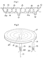
- Fig. 1 illustrates an integrally molded flat compact fluorescent lamp in accordance with a first embodiment of the present invention.
- the lamp comprises a glass envelope 10 composed of a molded channeled member 11 with a spiral channel 14 , and a planar member 13 .
- the channel 14 is formed by the walls 14a .
- the envelope contains integral tubes 12 formed in the channeled member 11 to which the electrode assemblies are flame-sealed later.
- the planar member 13 is fused at fused sections 15 and 16 of the walls 14a . Such fusing is accomplished by press sealing the channeled member 11 while the channeled member is still molten during vacuum-assisted sag molding.
- the sections 15 and 16 are vacuum tight and free from any inter-channel discharge leaks when the lamp is made since the glass of the walls 14a is fused to the planar member 13 . Such fusion between the members eliminates the laborious formation of the frit seals as was done previously with lamps of the present type.
- the weight of the envelope for 5-1/4 inches diameter lamp is 70 grams. Flame-sealing the electrode assemblies to the tubes 12 is a fast operation that is convenient for mass manufacturing.
- the envelope Prior to the sealing of the electrode assemblies, the envelope is processed to provide a phosphor layer on the interior surface of the envelope in a manner as discussed hereinbefore. The phosphor density of the phosphor is made smaller on the planar member than on the channeled member. Then, the envelope is evacuated and filled with a rare gas and mercury to a suitable pressure and sealed off to form the lamp.
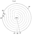
- Fig. 2 illustrates a modification of the above lamp with an external reflective layer 23 .
- the lamp comprises a like glass envelope 17 with tubes 18 and the externally-coated reflective layer 23 .
- the inner surfaces of the spiral channel are coated with the like phosphor layer, as discussed hereinbefore.
- Two electrode assemblies are used.
- a central electrode assembly has an exhaust tubulation 21 , leads 22 , and electron-emissive electrodes 20 disposed in a glass tube 19 .
- An outer electrode assembly has all of the components of the central one except the exhaust tubulation. These assemblies are sealed to the tubes 18 of the integrally molded member in a conventional flame-sealing operation.
- a completed lamp with a diameter of 5-1/4" weighs 80 grams.
- Fig. 3 illustrates an integrally molded flat compact fluorescent lamp in accordance with a second embodiment of the present invention.
- the lamp comprises an integrally molded glass envelope 24 with double spiral channels 28 and 29 running parallel all the way from the outer two electrodes 25 and 26 to a center common electrode 27 .
- the envelope 24 is composed of a channeled member integrally molded to a planar member as in the first embodiment. With the provision of the parallel spiral channels, the lamp voltage can be made low, yet providing an elongated total discharge path.
- the other configuration is the same as in the lamp of FIG. 2. Coating of the phosphor is also made after integrating the channeled member and the planar member into the envelope and before mounting the electrode assemblies, as discussed herein.
- Fig. 4 illustrates a flat compact fluorescent lamp in accordance with a third embodiment of the present invention.
- the lamp comprises an integrally molded glass envelope 30 with two parallel serpentine channels 33 and 34 extending from two top electrodes 31 and 32 to two bottom electrodes 35 and 36 .
- the other configuration is the same as in the lamp of FIG. 2. Coating the phosphor is also accomplished as discussed herein.
- Fig. 5 illustrates a flat compact fluorescent lamp in accordance with a fourth embodiment of the present invention.
- the lamp comprises an integrally molded glass envelope 41 composed of a channeled member 50 formed on its upper and lower sides respectively with upper and lower channels 37 and 38 , either in the form of a serpentine in the case of rectangular or square geometry, or spiral in the case of circular geometry.
- the channeled member 50 is fused to individual planar members 40 and 39 on opposite sides thereof, in the like manner as discussed with reference to the first embodiment.
- Two independent discharges can be established in the channels 37 and 38 by appropriately attaching the like electrodes and driving them.
- a pair of the like electrode assemblies as utilized in the second embodiment are inserted through tubes (not shown) formed to extend through the walls of the channeled member 50 into each of the channels.
- the inside surfaces of the channel walls of 37 and 38 are coated with phosphor (not shown) and the external surface of the one planar member 39 is coated with a reflective layer 43 .
- the phosphor layer is formed in the manner as discussed hereinbefore prior to mounting the electrode assemblies and by the use of holes of the tubes for introducing and discharging the phosphor slurry or powder.
- this "double-sided" flat compact fluorescent lamp will be suitable for LCD backlighting. If each channel is coated with phosphors emitting different colors or color temperatures, a variable color lamp can be provided by adjusting the power in each channel.
- planar member of any one of the above embodiments may be integrally formed with an additional channeled member with glass walls which define an additional convoluted channel.
- the glass walls of the additional channeled member on the planar member are fused to the existing channeled member in such a manner as to make the additional channel on the planar member in complementary with the channel of the channeled member for providing the two separate closed channels, as obtained in the embodiment of FIG. 5.
- an internal reflective layer may be formed on a selective portion of the lamp envelope beneath the phosphor layer.
- the internal reflective layer is also formed before providing the phosphor layer but after integrating the channeled member and the planar member into the envelope in the manner as discussed hereinbefore.
- Such internal reflective layer is preferred to be formed over a subtended angle of 10° to 300° about a center axis of the charge path formed in the channel.
- the channeled member in any one of the above embodiments and modifications may be also formed by press-molding, blow-molding, in addition to the vacuum-assisted sag molding, or in combination thereof.
Landscapes
- Chemical & Material Sciences (AREA)
- Engineering & Computer Science (AREA)
- Materials Engineering (AREA)
- Organic Chemistry (AREA)
- Manufacturing & Machinery (AREA)
- Vessels And Coating Films For Discharge Lamps (AREA)
- Manufacture Of Electron Tubes, Discharge Lamp Vessels, Lead-In Wires, And The Like (AREA)
Applications Claiming Priority (2)
| Application Number | Priority Date | Filing Date | Title |
|---|---|---|---|
| US08/759,382 US5811925A (en) | 1996-12-04 | 1996-12-04 | Integrally molded flat compact fluorescent lamp |
| US759382 | 1996-12-04 |
Publications (2)
| Publication Number | Publication Date |
|---|---|
| EP0848407A2 true EP0848407A2 (de) | 1998-06-17 |
| EP0848407A3 EP0848407A3 (de) | 1998-07-22 |
Family
ID=25055435
Family Applications (1)
| Application Number | Title | Priority Date | Filing Date |
|---|---|---|---|
| EP97121161A Withdrawn EP0848407A3 (de) | 1996-12-04 | 1997-12-02 | Einstückig gegossene flache Kompaktfluoreszenzlampe |
Country Status (3)
| Country | Link |
|---|---|
| US (1) | US5811925A (de) |
| EP (1) | EP0848407A3 (de) |
| JP (1) | JPH10188894A (de) |
Cited By (3)
| Publication number | Priority date | Publication date | Assignee | Title |
|---|---|---|---|---|
| US5331249A (en) * | 1988-09-27 | 1994-07-19 | Yazaki Corporation | Discharge tube |
| WO2002027747A1 (de) * | 2000-09-29 | 2002-04-04 | Patent-Treuhand-Gesellschaft für elektrische Glühlampen mbH | Dielektrische barriere-entladungslampe |
| WO2021042939A1 (zh) * | 2019-09-03 | 2021-03-11 | Oppo广东移动通信有限公司 | 电子设备、电池盖、及其制造方法 |
Families Citing this family (18)
| Publication number | Priority date | Publication date | Assignee | Title |
|---|---|---|---|---|
| US6118215A (en) * | 1998-08-07 | 2000-09-12 | Omnion Technologies, Inc. | Flat internal electrode for luminous gas discharge display and method of manufacture |
| US6559599B1 (en) * | 1998-11-17 | 2003-05-06 | Corning Incorporated | Internally channeled glass envelope with molded edge for affixing attachments |
| KR100588710B1 (ko) * | 1998-11-17 | 2006-06-13 | 코닝 인코포레이티드 | 부착물을 부착하기 위한 몰드 에지가 구비된 내부 채널형유리 관구 |
| US6452323B1 (en) | 1999-09-20 | 2002-09-17 | Omnion Technologies, Inc. | Luminous gas discharge display having dielectric sealing layer |
| KR100720412B1 (ko) * | 2000-10-31 | 2007-05-22 | 엘지.필립스 엘시디 주식회사 | 면 발광용 플랫램프 및 이를 구비한 액정표시장치 |
| US6836072B2 (en) * | 2001-11-02 | 2004-12-28 | Electro Plasma, Inc. | Low voltage high efficiency illuminated display having capacitive coupled electrodes |
| US7053555B2 (en) * | 2002-11-21 | 2006-05-30 | Matsushita Electric Industrial Co., Ltd. | Arc tube, discharge lamp, and production method of such arc tube, which enables brighter illuminance |
| US20050093423A1 (en) * | 2003-10-31 | 2005-05-05 | Cull Brian D. | Redundant flat lamp system |
| KR20060001337A (ko) * | 2004-06-30 | 2006-01-06 | 엘지.필립스 엘시디 주식회사 | 발광램프 및 이를 구비한 액정표시장치 |
| JP2006085943A (ja) * | 2004-09-14 | 2006-03-30 | Matsushita Electric Ind Co Ltd | 発光管、蛍光ランプ及び照明装置 |
| CN101596515A (zh) * | 2008-06-05 | 2009-12-09 | 奥斯兰姆有限公司 | 管内壁涂覆层形成方法和设备 |
| TWI378490B (en) * | 2008-07-04 | 2012-12-01 | Delta Electronics Inc | Fluorescent lamp with adjustable color temperature |
| DE102010033446B4 (de) * | 2010-08-04 | 2012-03-22 | Heraeus Noblelight Gmbh | Quecksilberdampflampe für eine homogene flächenhafte Bestrahlung |
| DE102011003427A1 (de) * | 2011-02-01 | 2012-08-02 | Osram Ag | Leuchte mit einer Entladungslampe, welche ein Entladungsgefäß aufweist, das als Flachspirale ausgebildet ist |
| EP3765896A1 (de) | 2018-03-13 | 2021-01-20 | Apple Inc. | Anzeigen mit direktbeleuchteten rückbeleuchtungseinheiten |
| US11526051B2 (en) | 2021-04-16 | 2022-12-13 | Apple Inc. | Displays with direct-lit backlight units |
| US11592706B2 (en) | 2021-04-16 | 2023-02-28 | Apple Inc. | Displays with direct-lit backlight units |
| US11513392B1 (en) | 2021-09-23 | 2022-11-29 | Apple Inc. | Direct-lit backlight units with optical films |
Citations (1)
| Publication number | Priority date | Publication date | Assignee | Title |
|---|---|---|---|---|
| US3226590A (en) * | 1960-11-15 | 1965-12-28 | Gen Electric | Fluorescent panel lamp |
Family Cites Families (11)
| Publication number | Priority date | Publication date | Assignee | Title |
|---|---|---|---|---|
| FR922052A (fr) * | 1944-12-21 | 1947-05-28 | Gen Electric Co Ltd | Lampes électriques à décharge perfectionnées |
| US2405518A (en) * | 1945-11-14 | 1946-08-06 | Igor B Polevitzky | Illuminating device |
| US2555749A (en) * | 1947-12-17 | 1951-06-05 | Krefft Hermann Eduard | Fluorescent lamp |
| US3258630A (en) * | 1962-02-09 | 1966-06-28 | Electric discharge lamps | |
| US3646383A (en) * | 1970-01-09 | 1972-02-29 | Gen Electric | Fluorescent panel lamp |
| CA1250887A (en) * | 1984-02-29 | 1989-03-07 | Iwasaki Electric Co., Ltd. | Light emitting tube and method for producing same |
| JPH01243361A (ja) * | 1988-03-25 | 1989-09-28 | Toshiba Electric Equip Corp | 面状けい光ランプ |
| US5220249A (en) * | 1990-10-08 | 1993-06-15 | Nec Corporation | Flat type fluorescent lamp and method of lighting |
| JPH06168702A (ja) * | 1992-11-30 | 1994-06-14 | Hitachi Ltd | 放電ランプ |
| US5536999A (en) * | 1994-12-02 | 1996-07-16 | Winsor Corporation | Planar fluorescent lamp with extended discharge channel |
| US5767618A (en) * | 1996-02-09 | 1998-06-16 | Matsushita Electric Works Research And Development Laboraties Inc. | Flat compact fluorescent lamp with inter-channel discharge suppression |
-
1996
- 1996-12-04 US US08/759,382 patent/US5811925A/en not_active Expired - Fee Related
-
1997
- 1997-11-25 JP JP9323640A patent/JPH10188894A/ja active Pending
- 1997-12-02 EP EP97121161A patent/EP0848407A3/de not_active Withdrawn
Patent Citations (1)
| Publication number | Priority date | Publication date | Assignee | Title |
|---|---|---|---|---|
| US3226590A (en) * | 1960-11-15 | 1965-12-28 | Gen Electric | Fluorescent panel lamp |
Non-Patent Citations (1)
| Title |
|---|
| Hicks et al., 13th Digital Avionics Systems Conference, Phoenix, Oct. 30 - Nov. 3, 1994, New York, IEEE, US, pages 630 - 635 * |
Cited By (4)
| Publication number | Priority date | Publication date | Assignee | Title |
|---|---|---|---|---|
| US5331249A (en) * | 1988-09-27 | 1994-07-19 | Yazaki Corporation | Discharge tube |
| WO2002027747A1 (de) * | 2000-09-29 | 2002-04-04 | Patent-Treuhand-Gesellschaft für elektrische Glühlampen mbH | Dielektrische barriere-entladungslampe |
| US6605899B2 (en) | 2000-09-29 | 2003-08-12 | Patent-Treuhand-Gesellschaft Fuer Elektrische Gluehlampen Mbh | Dielectric barrier discharge lamp |
| WO2021042939A1 (zh) * | 2019-09-03 | 2021-03-11 | Oppo广东移动通信有限公司 | 电子设备、电池盖、及其制造方法 |
Also Published As
| Publication number | Publication date |
|---|---|
| US5811925A (en) | 1998-09-22 |
| JPH10188894A (ja) | 1998-07-21 |
| EP0848407A3 (de) | 1998-07-22 |
Similar Documents
| Publication | Publication Date | Title |
|---|---|---|
| US5811925A (en) | Integrally molded flat compact fluorescent lamp | |
| US3501662A (en) | Planar or three-dimensional fluorescent lamp and method of manufacture | |
| US6836064B2 (en) | Gas discharge tube and display device using the same | |
| US6252345B1 (en) | Display panel and method of fabricating the same | |
| KR20050032597A (ko) | 평면 램프, 이의 제조 방법, 및 상기 평면 램프의 사용 방법 | |
| US5804914A (en) | Fluorescent lamp having additional and interior fluorescent surfaces to increase luminosity | |
| JPS59186245A (ja) | コンパクトけい光ランプ | |
| JPS614152A (ja) | 面状放電発光体 | |
| US6512331B1 (en) | Luminous display and method of making same | |
| JPS62157657A (ja) | 表示用けい光ランプ | |
| JPH0992208A (ja) | 平面型蛍光灯及びその隔壁の製造方法 | |
| EP0698913A2 (de) | Kompakte Leuchtstofflampe | |
| JPH0992154A (ja) | 渦巻き状蛍光ランプの製造方法 | |
| KR100697498B1 (ko) | 콤팩트 형광 램프 | |
| US6323593B1 (en) | Product and process for neon lamp | |
| TWI333581B (en) | Fluorescent flat lamp and structure of the same | |
| US6592808B1 (en) | Cermet sintering of ceramic discharge chambers | |
| US6486598B1 (en) | Compact fluorescent lamp and method for manufacturing | |
| US6559599B1 (en) | Internally channeled glass envelope with molded edge for affixing attachments | |
| JPH0737551A (ja) | 平面形蛍光ランプ | |
| US5903090A (en) | Automotive discharge lamp with fluidly communicable discharge and reservoir volumes | |
| JP2003187750A (ja) | 蛍光ランプおよび照明装置 | |
| JPS61133549A (ja) | 螢光ランプ | |
| CA1215100A (en) | Low pressure discharge lamp | |
| GB2036420A (en) | Electric Discharge Lamps |
Legal Events
| Date | Code | Title | Description |
|---|---|---|---|
| PUAI | Public reference made under article 153(3) epc to a published international application that has entered the european phase |
Free format text: ORIGINAL CODE: 0009012 |
|
| PUAL | Search report despatched |
Free format text: ORIGINAL CODE: 0009013 |
|
| AK | Designated contracting states |
Kind code of ref document: A2 Designated state(s): DE GB NL |
|
| AX | Request for extension of the european patent |
Free format text: AL;LT;LV;MK;RO;SI |
|
| AK | Designated contracting states |
Kind code of ref document: A3 Designated state(s): AT BE CH DE DK ES FI FR GB GR IE IT LI LU MC NL PT SE |
|
| AX | Request for extension of the european patent |
Free format text: AL;LT;LV;MK;RO;SI |
|
| 17P | Request for examination filed |
Effective date: 19980825 |
|
| AKX | Designation fees paid |
Free format text: DE GB NL |
|
| RBV | Designated contracting states (corrected) |
Designated state(s): DE GB NL |
|
| 17Q | First examination report despatched |
Effective date: 20020403 |
|
| GRAH | Despatch of communication of intention to grant a patent |
Free format text: ORIGINAL CODE: EPIDOS IGRA |
|
| STAA | Information on the status of an ep patent application or granted ep patent |
Free format text: STATUS: THE APPLICATION IS DEEMED TO BE WITHDRAWN |
|
| 18D | Application deemed to be withdrawn |
Effective date: 20030603 |