US6592808B1 - Cermet sintering of ceramic discharge chambers - Google Patents
Cermet sintering of ceramic discharge chambers Download PDFInfo
- Publication number
- US6592808B1 US6592808B1 US09/475,433 US47543399A US6592808B1 US 6592808 B1 US6592808 B1 US 6592808B1 US 47543399 A US47543399 A US 47543399A US 6592808 B1 US6592808 B1 US 6592808B1
- Authority
- US
- United States
- Prior art keywords
- tube
- ceramic
- alumina
- cermet
- chambers
- Prior art date
- Legal status (The legal status is an assumption and is not a legal conclusion. Google has not performed a legal analysis and makes no representation as to the accuracy of the status listed.)
- Expired - Fee Related
Links
- 239000000919 ceramic Substances 0.000 title claims abstract description 32
- 239000011195 cermet Substances 0.000 title claims abstract description 22
- 238000005245 sintering Methods 0.000 title claims description 15
- PNEYBMLMFCGWSK-UHFFFAOYSA-N aluminium oxide Inorganic materials [O-2].[O-2].[O-2].[Al+3].[Al+3] PNEYBMLMFCGWSK-UHFFFAOYSA-N 0.000 claims abstract description 26
- 238000004519 manufacturing process Methods 0.000 claims abstract description 7
- 238000000034 method Methods 0.000 claims description 19
- CPLXHLVBOLITMK-UHFFFAOYSA-N Magnesium oxide Chemical compound [Mg]=O CPLXHLVBOLITMK-UHFFFAOYSA-N 0.000 claims description 16
- ZOKXTWBITQBERF-UHFFFAOYSA-N Molybdenum Chemical compound [Mo] ZOKXTWBITQBERF-UHFFFAOYSA-N 0.000 claims description 12
- 239000000463 material Substances 0.000 claims description 12
- 229910052750 molybdenum Inorganic materials 0.000 claims description 12
- 239000011733 molybdenum Substances 0.000 claims description 12
- 239000000843 powder Substances 0.000 claims description 12
- 239000000203 mixture Substances 0.000 claims description 11
- 238000010891 electric arc Methods 0.000 claims description 10
- 239000011230 binding agent Substances 0.000 claims description 8
- 239000000395 magnesium oxide Substances 0.000 claims description 8
- 239000003870 refractory metal Substances 0.000 claims description 5
- 229910052593 corundum Inorganic materials 0.000 claims description 4
- WFKWXMTUELFFGS-UHFFFAOYSA-N tungsten Chemical compound [W] WFKWXMTUELFFGS-UHFFFAOYSA-N 0.000 claims description 4
- 229910052721 tungsten Inorganic materials 0.000 claims description 4
- 239000010937 tungsten Substances 0.000 claims description 4
- 229910001845 yogo sapphire Inorganic materials 0.000 claims description 4
- 238000002844 melting Methods 0.000 claims description 3
- 230000008018 melting Effects 0.000 claims description 3
- 239000002019 doping agent Substances 0.000 claims description 2
- 238000010304 firing Methods 0.000 claims description 2
- 229910052746 lanthanum Inorganic materials 0.000 claims 1
- FZLIPJUXYLNCLC-UHFFFAOYSA-N lanthanum atom Chemical compound [La] FZLIPJUXYLNCLC-UHFFFAOYSA-N 0.000 claims 1
- 229910052727 yttrium Inorganic materials 0.000 claims 1
- VWQVUPCCIRVNHF-UHFFFAOYSA-N yttrium atom Chemical compound [Y] VWQVUPCCIRVNHF-UHFFFAOYSA-N 0.000 claims 1
- 230000007704 transition Effects 0.000 description 8
- 239000004020 conductor Substances 0.000 description 7
- 229910001507 metal halide Inorganic materials 0.000 description 7
- 150000005309 metal halides Chemical class 0.000 description 7
- 230000008569 process Effects 0.000 description 5
- DGAQECJNVWCQMB-PUAWFVPOSA-M Ilexoside XXIX Chemical compound C[C@@H]1CC[C@@]2(CC[C@@]3(C(=CC[C@H]4[C@]3(CC[C@@H]5[C@@]4(CC[C@@H](C5(C)C)OS(=O)(=O)[O-])C)C)[C@@H]2[C@]1(C)O)C)C(=O)O[C@H]6[C@@H]([C@H]([C@@H]([C@H](O6)CO)O)O)O.[Na+] DGAQECJNVWCQMB-PUAWFVPOSA-M 0.000 description 4
- 229910052751 metal Inorganic materials 0.000 description 4
- 239000002184 metal Substances 0.000 description 4
- 229910052708 sodium Inorganic materials 0.000 description 4
- 239000011734 sodium Substances 0.000 description 4
- VYPSYNLAJGMNEJ-UHFFFAOYSA-N Silicium dioxide Chemical compound O=[Si]=O VYPSYNLAJGMNEJ-UHFFFAOYSA-N 0.000 description 3
- 238000007723 die pressing method Methods 0.000 description 3
- 239000011521 glass Substances 0.000 description 3
- 238000000926 separation method Methods 0.000 description 3
- UFHFLCQGNIYNRP-UHFFFAOYSA-N Hydrogen Chemical compound [H][H] UFHFLCQGNIYNRP-UHFFFAOYSA-N 0.000 description 2
- 230000008901 benefit Effects 0.000 description 2
- 230000015572 biosynthetic process Effects 0.000 description 2
- 229910010293 ceramic material Inorganic materials 0.000 description 2
- 239000000470 constituent Substances 0.000 description 2
- 230000003247 decreasing effect Effects 0.000 description 2
- 238000009826 distribution Methods 0.000 description 2
- 239000005350 fused silica glass Substances 0.000 description 2
- 239000007789 gas Substances 0.000 description 2
- 238000010438 heat treatment Methods 0.000 description 2
- 239000001257 hydrogen Substances 0.000 description 2
- 229910052739 hydrogen Inorganic materials 0.000 description 2
- 238000012986 modification Methods 0.000 description 2
- 230000004048 modification Effects 0.000 description 2
- 239000002002 slurry Substances 0.000 description 2
- 239000006057 Non-nutritive feed additive Substances 0.000 description 1
- 229910052782 aluminium Inorganic materials 0.000 description 1
- XAGFODPZIPBFFR-UHFFFAOYSA-N aluminium Chemical compound [Al] XAGFODPZIPBFFR-UHFFFAOYSA-N 0.000 description 1
- UNQHSZOIUSRWHT-UHFFFAOYSA-N aluminum molybdenum Chemical compound [Al].[Mo] UNQHSZOIUSRWHT-UHFFFAOYSA-N 0.000 description 1
- 230000009286 beneficial effect Effects 0.000 description 1
- 238000006243 chemical reaction Methods 0.000 description 1
- 239000008367 deionised water Substances 0.000 description 1
- 229910021641 deionized water Inorganic materials 0.000 description 1
- 238000000280 densification Methods 0.000 description 1
- RZQFCZYXPRKMTP-UHFFFAOYSA-K dysprosium(3+);triiodide Chemical compound [I-].[I-].[I-].[Dy+3] RZQFCZYXPRKMTP-UHFFFAOYSA-K 0.000 description 1
- 230000000694 effects Effects 0.000 description 1
- 238000001125 extrusion Methods 0.000 description 1
- 239000010419 fine particle Substances 0.000 description 1
- 239000008187 granular material Substances 0.000 description 1
- 150000004820 halides Chemical class 0.000 description 1
- 239000012535 impurity Substances 0.000 description 1
- 238000002347 injection Methods 0.000 description 1
- 239000007924 injection Substances 0.000 description 1
- 238000001746 injection moulding Methods 0.000 description 1
- 238000011068 loading method Methods 0.000 description 1
- 230000013011 mating Effects 0.000 description 1
- QSHDDOUJBYECFT-UHFFFAOYSA-N mercury Chemical compound [Hg] QSHDDOUJBYECFT-UHFFFAOYSA-N 0.000 description 1
- 229910052753 mercury Inorganic materials 0.000 description 1
- 229920000609 methyl cellulose Polymers 0.000 description 1
- 239000001923 methylcellulose Substances 0.000 description 1
- 235000010981 methylcellulose Nutrition 0.000 description 1
- VLAPMBHFAWRUQP-UHFFFAOYSA-L molybdic acid Chemical compound O[Mo](O)(=O)=O VLAPMBHFAWRUQP-UHFFFAOYSA-L 0.000 description 1
- 229910052758 niobium Inorganic materials 0.000 description 1
- 239000010955 niobium Substances 0.000 description 1
- GUCVJGMIXFAOAE-UHFFFAOYSA-N niobium atom Chemical compound [Nb] GUCVJGMIXFAOAE-UHFFFAOYSA-N 0.000 description 1
- 239000012466 permeate Substances 0.000 description 1
- 229920002401 polyacrylamide Polymers 0.000 description 1
- 239000010453 quartz Substances 0.000 description 1
- 230000005855 radiation Effects 0.000 description 1
- 238000009877 rendering Methods 0.000 description 1
- 230000004044 response Effects 0.000 description 1
- 150000004760 silicates Chemical class 0.000 description 1
- 229910052710 silicon Inorganic materials 0.000 description 1
- 239000010703 silicon Substances 0.000 description 1
- -1 silicon halide Chemical class 0.000 description 1
- 238000002791 soaking Methods 0.000 description 1
- 239000007787 solid Substances 0.000 description 1
- 239000000243 solution Substances 0.000 description 1
- 230000003595 spectral effect Effects 0.000 description 1
- XLYOFNOQVPJJNP-UHFFFAOYSA-N water Chemical compound O XLYOFNOQVPJJNP-UHFFFAOYSA-N 0.000 description 1
Images

Classifications
-
- C—CHEMISTRY; METALLURGY
- C04—CEMENTS; CONCRETE; ARTIFICIAL STONE; CERAMICS; REFRACTORIES
- C04B—LIME, MAGNESIA; SLAG; CEMENTS; COMPOSITIONS THEREOF, e.g. MORTARS, CONCRETE OR LIKE BUILDING MATERIALS; ARTIFICIAL STONE; CERAMICS; REFRACTORIES; TREATMENT OF NATURAL STONE
- C04B35/00—Shaped ceramic products characterised by their composition; Ceramics compositions; Processing powders of inorganic compounds preparatory to the manufacturing of ceramic products
- C04B35/01—Shaped ceramic products characterised by their composition; Ceramics compositions; Processing powders of inorganic compounds preparatory to the manufacturing of ceramic products based on oxide ceramics
- C04B35/10—Shaped ceramic products characterised by their composition; Ceramics compositions; Processing powders of inorganic compounds preparatory to the manufacturing of ceramic products based on oxide ceramics based on aluminium oxide
- C04B35/111—Fine ceramics
- C04B35/117—Composites
-
- B—PERFORMING OPERATIONS; TRANSPORTING
- B22—CASTING; POWDER METALLURGY
- B22F—WORKING METALLIC POWDER; MANUFACTURE OF ARTICLES FROM METALLIC POWDER; MAKING METALLIC POWDER; APPARATUS OR DEVICES SPECIALLY ADAPTED FOR METALLIC POWDER
- B22F7/00—Manufacture of composite layers, workpieces, or articles, comprising metallic powder, by sintering the powder, with or without compacting wherein at least one part is obtained by sintering or compression
- B22F7/06—Manufacture of composite layers, workpieces, or articles, comprising metallic powder, by sintering the powder, with or without compacting wherein at least one part is obtained by sintering or compression of composite workpieces or articles from parts, e.g. to form tipped tools
- B22F7/062—Manufacture of composite layers, workpieces, or articles, comprising metallic powder, by sintering the powder, with or without compacting wherein at least one part is obtained by sintering or compression of composite workpieces or articles from parts, e.g. to form tipped tools involving the connection or repairing of preformed parts
-
- H—ELECTRICITY
- H01—ELECTRIC ELEMENTS
- H01J—ELECTRIC DISCHARGE TUBES OR DISCHARGE LAMPS
- H01J9/00—Apparatus or processes specially adapted for the manufacture, installation, removal, maintenance of electric discharge tubes, discharge lamps, or parts thereof; Recovery of material from discharge tubes or lamps
- H01J9/24—Manufacture or joining of vessels, leading-in conductors or bases
- H01J9/245—Manufacture or joining of vessels, leading-in conductors or bases specially adapted for gas discharge tubes or lamps
-
- C—CHEMISTRY; METALLURGY
- C04—CEMENTS; CONCRETE; ARTIFICIAL STONE; CERAMICS; REFRACTORIES
- C04B—LIME, MAGNESIA; SLAG; CEMENTS; COMPOSITIONS THEREOF, e.g. MORTARS, CONCRETE OR LIKE BUILDING MATERIALS; ARTIFICIAL STONE; CERAMICS; REFRACTORIES; TREATMENT OF NATURAL STONE
- C04B2235/00—Aspects relating to ceramic starting mixtures or sintered ceramic products
- C04B2235/02—Composition of constituents of the starting material or of secondary phases of the final product
- C04B2235/30—Constituents and secondary phases not being of a fibrous nature
- C04B2235/32—Metal oxides, mixed metal oxides, or oxide-forming salts thereof, e.g. carbonates, nitrates, (oxy)hydroxides, chlorides
- C04B2235/3205—Alkaline earth oxides or oxide forming salts thereof, e.g. beryllium oxide
- C04B2235/3206—Magnesium oxides or oxide-forming salts thereof
-
- C—CHEMISTRY; METALLURGY
- C04—CEMENTS; CONCRETE; ARTIFICIAL STONE; CERAMICS; REFRACTORIES
- C04B—LIME, MAGNESIA; SLAG; CEMENTS; COMPOSITIONS THEREOF, e.g. MORTARS, CONCRETE OR LIKE BUILDING MATERIALS; ARTIFICIAL STONE; CERAMICS; REFRACTORIES; TREATMENT OF NATURAL STONE
- C04B2235/00—Aspects relating to ceramic starting mixtures or sintered ceramic products
- C04B2235/02—Composition of constituents of the starting material or of secondary phases of the final product
- C04B2235/30—Constituents and secondary phases not being of a fibrous nature
- C04B2235/32—Metal oxides, mixed metal oxides, or oxide-forming salts thereof, e.g. carbonates, nitrates, (oxy)hydroxides, chlorides
- C04B2235/3224—Rare earth oxide or oxide forming salts thereof, e.g. scandium oxide
- C04B2235/3225—Yttrium oxide or oxide-forming salts thereof
-
- C—CHEMISTRY; METALLURGY
- C04—CEMENTS; CONCRETE; ARTIFICIAL STONE; CERAMICS; REFRACTORIES
- C04B—LIME, MAGNESIA; SLAG; CEMENTS; COMPOSITIONS THEREOF, e.g. MORTARS, CONCRETE OR LIKE BUILDING MATERIALS; ARTIFICIAL STONE; CERAMICS; REFRACTORIES; TREATMENT OF NATURAL STONE
- C04B2235/00—Aspects relating to ceramic starting mixtures or sintered ceramic products
- C04B2235/02—Composition of constituents of the starting material or of secondary phases of the final product
- C04B2235/30—Constituents and secondary phases not being of a fibrous nature
- C04B2235/32—Metal oxides, mixed metal oxides, or oxide-forming salts thereof, e.g. carbonates, nitrates, (oxy)hydroxides, chlorides
- C04B2235/3224—Rare earth oxide or oxide forming salts thereof, e.g. scandium oxide
- C04B2235/3227—Lanthanum oxide or oxide-forming salts thereof
-
- C—CHEMISTRY; METALLURGY
- C04—CEMENTS; CONCRETE; ARTIFICIAL STONE; CERAMICS; REFRACTORIES
- C04B—LIME, MAGNESIA; SLAG; CEMENTS; COMPOSITIONS THEREOF, e.g. MORTARS, CONCRETE OR LIKE BUILDING MATERIALS; ARTIFICIAL STONE; CERAMICS; REFRACTORIES; TREATMENT OF NATURAL STONE
- C04B2235/00—Aspects relating to ceramic starting mixtures or sintered ceramic products
- C04B2235/02—Composition of constituents of the starting material or of secondary phases of the final product
- C04B2235/30—Constituents and secondary phases not being of a fibrous nature
- C04B2235/40—Metallic constituents or additives not added as binding phase
- C04B2235/404—Refractory metals
-
- C—CHEMISTRY; METALLURGY
- C04—CEMENTS; CONCRETE; ARTIFICIAL STONE; CERAMICS; REFRACTORIES
- C04B—LIME, MAGNESIA; SLAG; CEMENTS; COMPOSITIONS THEREOF, e.g. MORTARS, CONCRETE OR LIKE BUILDING MATERIALS; ARTIFICIAL STONE; CERAMICS; REFRACTORIES; TREATMENT OF NATURAL STONE
- C04B2235/00—Aspects relating to ceramic starting mixtures or sintered ceramic products
- C04B2235/60—Aspects relating to the preparation, properties or mechanical treatment of green bodies or pre-forms
- C04B2235/602—Making the green bodies or pre-forms by moulding
- C04B2235/6021—Extrusion moulding
-
- C—CHEMISTRY; METALLURGY
- C04—CEMENTS; CONCRETE; ARTIFICIAL STONE; CERAMICS; REFRACTORIES
- C04B—LIME, MAGNESIA; SLAG; CEMENTS; COMPOSITIONS THEREOF, e.g. MORTARS, CONCRETE OR LIKE BUILDING MATERIALS; ARTIFICIAL STONE; CERAMICS; REFRACTORIES; TREATMENT OF NATURAL STONE
- C04B2235/00—Aspects relating to ceramic starting mixtures or sintered ceramic products
- C04B2235/70—Aspects relating to sintered or melt-casted ceramic products
- C04B2235/80—Phases present in the sintered or melt-cast ceramic products other than the main phase
-
- C—CHEMISTRY; METALLURGY
- C04—CEMENTS; CONCRETE; ARTIFICIAL STONE; CERAMICS; REFRACTORIES
- C04B—LIME, MAGNESIA; SLAG; CEMENTS; COMPOSITIONS THEREOF, e.g. MORTARS, CONCRETE OR LIKE BUILDING MATERIALS; ARTIFICIAL STONE; CERAMICS; REFRACTORIES; TREATMENT OF NATURAL STONE
- C04B2235/00—Aspects relating to ceramic starting mixtures or sintered ceramic products
- C04B2235/70—Aspects relating to sintered or melt-casted ceramic products
- C04B2235/94—Products characterised by their shape
-
- Y—GENERAL TAGGING OF NEW TECHNOLOGICAL DEVELOPMENTS; GENERAL TAGGING OF CROSS-SECTIONAL TECHNOLOGIES SPANNING OVER SEVERAL SECTIONS OF THE IPC; TECHNICAL SUBJECTS COVERED BY FORMER USPC CROSS-REFERENCE ART COLLECTIONS [XRACs] AND DIGESTS
- Y10—TECHNICAL SUBJECTS COVERED BY FORMER USPC
- Y10T—TECHNICAL SUBJECTS COVERED BY FORMER US CLASSIFICATION
- Y10T428/00—Stock material or miscellaneous articles
- Y10T428/13—Hollow or container type article [e.g., tube, vase, etc.]
- Y10T428/1352—Polymer or resin containing [i.e., natural or synthetic]
- Y10T428/139—Open-ended, self-supporting conduit, cylinder, or tube-type article
-
- Y—GENERAL TAGGING OF NEW TECHNOLOGICAL DEVELOPMENTS; GENERAL TAGGING OF CROSS-SECTIONAL TECHNOLOGIES SPANNING OVER SEVERAL SECTIONS OF THE IPC; TECHNICAL SUBJECTS COVERED BY FORMER USPC CROSS-REFERENCE ART COLLECTIONS [XRACs] AND DIGESTS
- Y10—TECHNICAL SUBJECTS COVERED BY FORMER USPC
- Y10T—TECHNICAL SUBJECTS COVERED BY FORMER US CLASSIFICATION
- Y10T428/00—Stock material or miscellaneous articles
- Y10T428/13—Hollow or container type article [e.g., tube, vase, etc.]
- Y10T428/1352—Polymer or resin containing [i.e., natural or synthetic]
- Y10T428/1397—Single layer [continuous layer]
Definitions
- This invention relates to generally lighting, and more particularly, to ceramic discharge chambers for a lamp, such as a ceramic metal halide lamp or a high pressure sodium discharge lamp.
- the present invention relates generally to lighting, and more specifically, to a ceramic arc chamber for a discharge lamp, such as a ceramic metal halide lamp.
- This invention relates particularly to a method of manufacturing ceramic arc chambers, and more particularly, to a method for sintering ceramic arc chambers.
- Discharge lamps produce light by ionizing a fill such as a mixture of metal halides and mercury with an electric arc passing between two electrodes.
- the electrodes and the fill are sealed within a translucent or transparent discharge chamber which maintains the pressure of the energized fill material and allows the emitted light to pass through it.
- the fill also known as a “dose”, emits a desired spectral energy distribution in response to being excited by the electric arc.
- the discharge chamber in a discharge lamp was formed from a vitreous material such as fused quartz, which was shaped into a desired chamber geometry after being heated to a softened state.
- Fused quartz has certain disadvantages which arise from its reactive properties at high operating temperatures. For example, at temperatures greater than about 950 to 1,000° C., the halide fill reacts with the glass to produce silicates and silicon halide, reducing the fill constituents. Elevated temperatures also cause sodium to permeate through the quartz wall. These fill depletions cause color shift over time, which reduces the useful life of the lamp.
- Ceramic discharge chambers were developed to operate at high temperatures for improved color temperatures, color renderings, luminous efficacies, while significantly reducing reactions with the fill material.
- U.S. Pat. Nos. 4,285,732 and 5,725,827 disclose translucent polycrystalline sintered bodies where visible wavelength radiation is sufficiently able to pass through to make the body useful for use as an arc tube.
- ceramic discharge chambers are constructed from a number of parts extruded or die pressed from a ceramic powder and then sintered together.
- five ceramic parts are used to construct the discharge chamber of a metal halide lamp.
- Two end plugs with a central bore are fabricated by die pressing a mixture of a ceramic powder and inorganic binder.
- a central cylinder and the two legs are produced by extruding a ceramic powder/binder mixture through a die. After forming the part, it is typically air sintered between 900-1400° C. to remove organic processing aids. Assembly of the discharge chamber requires tacking of the legs to the cylinder plugs, and the end plugs into the end of the central cylinder. This assembly is then sintered to form joins which are bonded by controlled shrinkage of the individual parts.
- two and three component lamps have been developed and include end pieces of tubes/end caps and a central body.
- the components are horizontally aligned within a molybdenum sintering tube.
- the sintering process performed in molybdenum tubes is a relatively expensive operation. More particularly, a 3′ molybdenum tube costs several hundred dollars per piece. Accordingly, it would be desirable to provide an alternative housing within which a ceramic discharge chamber can be sintered.
- a method for making a ceramic discharge chamber by forming a plurality of chamber components and assembling the chamber components into a chamber preform.
- the chamber preform is then positioned within a tube, the tube being comprised of an alumina cermet.
- the tube containing the chamber preform is then sintered.
- This exemplary embodiment of the invention advantageously reduces the unit cost of manufacture of the ceramic discharge chambers. More particularly, the alumina cermet tubes of the present invention are relatively inexpensive yet exhibit long operational life. Furthermore, the alumina cermet tubes reduce the formation of blemishes in the arc discharge chambers which may occur as a result of a seam which is present in a traditional molybdenum tube.
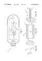
- FIG. 1 illustrates a light source which includes a ceramic discharge chamber according to an exemplary embodiment of the invention
- FIGS. 2A-2C illustrate components of a discharge chamber for a metal halide lamp
- FIG. 3 illustrates a partial view in cross section of a alumina cermet tube in a loaded condition in accord with the present invention.
- FIG. 1 illustrates a discharge lamp 10 according to an exemplary embodiment of the invention.
- Discharge lamp 10 includes a discharge chamber 50 which contains two electrodes 52 , 54 and fill material. Electrodes 52 , 54 are connected to conductors 56 , 58 , which apply a potential difference across the electrodes. In operation, the electrodes 52 , 54 produce an arc which ionizes a fill material to produce a plasma in the discharge chamber 50 .
- the emission characteristics of the light produced by the plasma depend primarily on the constituents of the fill material, the voltage across the electrodes, the temperature distribution of the chamber, the pressure in the chamber, and the geometry of the chamber.
- the fill may typically comprise a mixture of Hg, a rare gas such as Ar or Xe and a metal halide such as NaI, TlI, DyI 3 .
- the fill material typically comprises sodium, a rare gas, and Hg.
- Other fill materials are also well known in the art, and the present invention is believed to be suitable for operation with any of those recognized ionizable materials.
- the discharge chamber 50 comprises a central body portion 60 and two leg portions 62 , 64 .
- the ends of the electrodes 52 , 54 are typically located near the opposite ends of the body portion 60 .
- the electrodes are connected to a power supply by the conductors 56 , 58 which are disposed within a central bore of each leg portion 62 , 64 .
- the electrodes are typically comprised of tungsten.
- the conductors typically comprise niobium and molybdenum which have thermal expansion coefficients close to that of alumina to reduce thermally induced stresses on the alumina leg portion 62 , 64 .
- the discharge chamber 50 is sealed at the ends of the leg portions 62 , 64 with seals 66 , 68 .
- the seal 66 , 68 typically comprise a disprosia-alumina-silica glass that can be formed by placing a glass frit in the shape of a ring around one of the conductors, eg. 56 , aligning the discharge chamber 50 vertically and melting the frit. The melted glass then flows down into the leg 62 , forming a seal between the conductor 56 and the leg 62 . The discharge chamber is then turned upside down to seal the other leg 64 after being filled with the fill material.
- the leg portion 62 , 64 extends axially away from the center of the discharge chamber 50 .
- the dimensions of the leg portions 62 , 64 are selected over the temperature of the seal 66 , 68 by desired amount with respect to the center of the discharge chamber 50 .
- the leg portion portions have a length of about 10-15 mm, an inner diameter of 0.8-1.0 mm and an outer diameter of about 2.5-3.0 mm to lower the temperature at the seal 66 , 68 to about 600 to 7000° C., which is about 400° C. less than the temperature at the center of the discharge chamber.
- the leg portions In a 35 watt lamp, the leg portions have a length of about 10-15 mm, an inner diameter of 0.7 to 0.8 mm and an outer diameter of about 2.0-2.5 mm. In a 150 watt lamp, the leg portions have a length of about 12-15 mm and an inner diameter of about 0.9-1.1 mm, and an outer diameter of about 2.5-3.0 mm.
- the body portion 60 of the discharge chamber is typically substantially cylindrical.
- the body portion typically has an inner diameter of about 7 mm and outer diameter of about 8.5 mm.
- the body portion typically has an inner diameter of about 5 mm and an outer diameter of about 6.5 mm.
- the body portion typically has an inner diameter of about 9.5 mm and an outer diameter of 11.5 mm.
- FIGS. 2A-2C illustrate components of a discharge chamber formed from three elements.
- a body member 122 is shown which is substantially cylindrical.
- the body member 122 of FIG. 1B can be formed by injection molding, die pressing, or by any other technique known in the art.
- the body member 122 can also be formed by extrusion.
- the leg member 124 is depicted which includes a leg portion 112 and a transition portion 114 . Both the leg portion 112 and the transition portion 114 include a central bore 109 which houses one of the two electrodes and the conductor. Transition portion 114 may be generally in the form of a plug which fits inside the end of the body member 122 . Transition portion 114 typically has a circumference which is greater than the circumference of the leg portion 112 . Transition portion 114 typically includes a radially directed flange 115 which projects radially outwardly from transition portion 114 .
- the radially directed flange 115 provides a shoulder 117 which rests against the end 119 of the body member 122 during assembly and fixes the relative axial position of leg member 124 with respect to the body member 122 .
- “Axial” refers to an axis through the central bores 107 , 109 in leg portions 112 , 126 .
- the radially directed flange 115 provides the advantage of the total length of the assembled discharge chamber, e.g. measured from the end 118 of leg member 120 to the opposite end 116 of leg member 124 can be maintained to within a tight dimensional tolerance.
- the total length of the discharge chamber typically effects the separation between the electrodes, since the electrodes are typically referenced to the ends 116 , 118 of the leg portions, 120 , 126 during assembly.
- the conductor may be crimped at a fixed distance from the end of the electrode, which crimp rests against of the leg portion to fix the axial position of the electrode with respect to the leg portion.
- the separation of the electrodes is determined by the position of the leg member 124 with respect to the body member 122 which can be precisely controlled by the radially directed flange 115 .
- the radially directed flange 115 thus allows the electrodes to be consistently positioned to have a precise separation distance, which provides consistency and quality of the light produced.
- the body member 122 and the leg members 120 , 124 can be constructed by die pressing a mixture of ceramic powder in a binder in to a solid cylinder. Alternatively, the mixture can be extruded or injection molded. As will be recognized by the skilled artisan, depending on which process of manufacture is used, the mixture comprises various amounts of ceramic powder and organic binder. Subsequent to formation, the binder is removed from the green part, typically by thermopyrollisis, to form a bisque-fired part. The machined parts are typically assembled prior to sintering to allow the sintering step to bond the parts together.
- the densities of the bisque-fired parts used to form the body member 122 and the leg members 120 , 124 are selected to achieve different degrees of shrinkage during the sintering step.
- the different densities in the bisque-fired parts may achieved by using ceramic powders having different surface areas.
- the surface area of the ceramic powder used to form body member 122 may be 6-10 meters squared per gram, while the surface area of the ceramic body used to form the leg members 120 and 124 may be 2-3 meters squared per gram.
- the finer powder in the body member 122 causes the bisque-fired body member 122 to have a lower density than the bisque-fired leg members 120 and 124 made from the coarser powder. Because the bisque-fired body member is less dense than the bisque-fired leg members, the body portion shrinks to a greater degree (eg 3-10%) during sintering than the transition portion 114 to form a seal along transition portion 114 .
- the sintering step may be carried out by heating the bisque-fired parts in hydrogen having a dew point of about 10-15°.
- the temperatures increase from room temperature to about 1300° C. over a two hour period.
- the temperature is held to about 1300° C. for about 2 hours.
- the temperature is increased by about 100° C. per hour up to a maximum temperature of about 1850-1880° C.
- the temperature is held at 1850-1880° C. for about 3.5 hours.
- the temperature is decreased from room temperature for two hours.
- the resulting ceramic material comprises densely sintered polycrystalline aluminum.
- the assembled arc discharge chambers 210 are axially aligned within alumina cermet tube 212 .
- a wire 214 preferably of tungsten or other suitable metal, is run axially through the aligned arc discharge chamber parts 210 to suspend the bodies within the tube environment.
- This process is beneficial from the perspective that the metal component of the cermet material, more fully described herinbelow, forms a dominant component of the atmosphere surrounding the arc discharge chambers during the sintering stage.
- This metallic component in the atmosphere forms a relatively large portion of the partial pressure thereof and is advantageous in controlling introduction of impurities and structuring grain growth during sintering of the components.
- a plurality of tubes may be loaded into a furnace and sintering may be carried out by heating the bisque-fired parts in hydrogen having a dew point of about 0-10° C.
- the temperature is increased from room temperature to about 1300° C. over a two hour period.
- the temperature is held at about 1300° C. for about two hours.
- the temperature is increased up to a maximum temperature of 1850-1880° C. and held at 1850-1880° C. for about 3-10 hours.
- the temperature is decreased to room temperature over about two hours.
- the arc discharge chamber components can be manufactured by any process and be finally sintered in accord with this exemplary embodiment of the present invention.
- the alumina cermet is an Al 2 O 3 ceramic material containing a portion of a metal as a separate phase.
- a cermet for instance, could be an Al 2 O 3 ceramic containing molybdenum, tungsten or other refractory metal with a melting point greater than 2000° C.
- the cermet will be an aluminum-molybdenum cermet. More preferably, the cermet will include between 1-30 volume percent molybdenum.
- the cermet is preferably doped with magnesia. Magnesia helps reduce any potential sticking between lamp parts and tube and helps prevent MgO loss in the sintered lamp parts.
- Al 2 O 3 and binder mixtures of the type (preferably including magnesia) described above in the context of arc chamber manufacture could be extruded in the form of the sintering tube.
- the extruded alumina tube could then be doped with molybdenum by soaking the tube in a solution of molybdic acid and firing the tube.
- the process will yield a tube having between 1 and 30 volume percent molybdenum.
- alumina refractory granules can be wet milled in deionized water together with up to 0.5 weight percent of magnesia to promote densification and inhibit grain growth.
- the desired refractory metal can then be added to the powder slurry to achieve the desired dopant level.
- the slurry is subsequently dried, sieved through a micron mesh and finally rolled to aglomerate most of the fine particles below 50 microns in diameter.
- the alumina/metal powder is then combined with a binder such as methyl cellulose or polyacrylamide, extruded into the form of a tube and sintered.
Landscapes
- Chemical & Material Sciences (AREA)
- Engineering & Computer Science (AREA)
- Manufacturing & Machinery (AREA)
- Composite Materials (AREA)
- Materials Engineering (AREA)
- Ceramic Engineering (AREA)
- Mechanical Engineering (AREA)
- Structural Engineering (AREA)
- Organic Chemistry (AREA)
- Vessels And Coating Films For Discharge Lamps (AREA)
Abstract
A method of making a ceramic discharge chamber comprising forming a plurality of preform chambers by assembling at least two ceramic components. The preform chambers are axially aligned within a tube, comprised of an alumina cermet. The tube containing the preform chambers is then fired at a temperature of at least 900° C.
Description
This invention relates to generally lighting, and more particularly, to ceramic discharge chambers for a lamp, such as a ceramic metal halide lamp or a high pressure sodium discharge lamp.
The present invention relates generally to lighting, and more specifically, to a ceramic arc chamber for a discharge lamp, such as a ceramic metal halide lamp. This invention relates particularly to a method of manufacturing ceramic arc chambers, and more particularly, to a method for sintering ceramic arc chambers.
Discharge lamps produce light by ionizing a fill such as a mixture of metal halides and mercury with an electric arc passing between two electrodes. The electrodes and the fill are sealed within a translucent or transparent discharge chamber which maintains the pressure of the energized fill material and allows the emitted light to pass through it. The fill, also known as a “dose”, emits a desired spectral energy distribution in response to being excited by the electric arc.
Initially, the discharge chamber in a discharge lamp was formed from a vitreous material such as fused quartz, which was shaped into a desired chamber geometry after being heated to a softened state. Fused quartz, however, has certain disadvantages which arise from its reactive properties at high operating temperatures. For example, at temperatures greater than about 950 to 1,000° C., the halide fill reacts with the glass to produce silicates and silicon halide, reducing the fill constituents. Elevated temperatures also cause sodium to permeate through the quartz wall. These fill depletions cause color shift over time, which reduces the useful life of the lamp.
Ceramic discharge chambers were developed to operate at high temperatures for improved color temperatures, color renderings, luminous efficacies, while significantly reducing reactions with the fill material. U.S. Pat. Nos. 4,285,732 and 5,725,827, for example, disclose translucent polycrystalline sintered bodies where visible wavelength radiation is sufficiently able to pass through to make the body useful for use as an arc tube.
Typically, ceramic discharge chambers are constructed from a number of parts extruded or die pressed from a ceramic powder and then sintered together. For example, referring now to European Patent Application No. 0587238, five ceramic parts are used to construct the discharge chamber of a metal halide lamp. Two end plugs with a central bore are fabricated by die pressing a mixture of a ceramic powder and inorganic binder. A central cylinder and the two legs are produced by extruding a ceramic powder/binder mixture through a die. After forming the part, it is typically air sintered between 900-1400° C. to remove organic processing aids. Assembly of the discharge chamber requires tacking of the legs to the cylinder plugs, and the end plugs into the end of the central cylinder. This assembly is then sintered to form joins which are bonded by controlled shrinkage of the individual parts.
In alternative structures, two and three component lamps have been developed and include end pieces of tubes/end caps and a central body. Typically, to facilitate the appropriate binding and mating of these components, the components are horizontally aligned within a molybdenum sintering tube. The sintering process performed in molybdenum tubes is a relatively expensive operation. More particularly, a 3′ molybdenum tube costs several hundred dollars per piece. Accordingly, it would be desirable to provide an alternative housing within which a ceramic discharge chamber can be sintered.
According to an exemplary embodiment of this invention, a method is provided for making a ceramic discharge chamber by forming a plurality of chamber components and assembling the chamber components into a chamber preform. The chamber preform is then positioned within a tube, the tube being comprised of an alumina cermet. The tube containing the chamber preform is then sintered.
This exemplary embodiment of the invention advantageously reduces the unit cost of manufacture of the ceramic discharge chambers. More particularly, the alumina cermet tubes of the present invention are relatively inexpensive yet exhibit long operational life. Furthermore, the alumina cermet tubes reduce the formation of blemishes in the arc discharge chambers which may occur as a result of a seam which is present in a traditional molybdenum tube.
Other features and advantages of the invention will be more readily understood upon reading the following detailed description in conjunction with the drawings in which:
FIG. 1 illustrates a light source which includes a ceramic discharge chamber according to an exemplary embodiment of the invention;
FIGS. 2A-2C illustrate components of a discharge chamber for a metal halide lamp, and
FIG. 3 illustrates a partial view in cross section of a alumina cermet tube in a loaded condition in accord with the present invention.
FIG. 1 illustrates a discharge lamp 10 according to an exemplary embodiment of the invention. Discharge lamp 10 includes a discharge chamber 50 which contains two electrodes 52, 54 and fill material. Electrodes 52, 54 are connected to conductors 56, 58, which apply a potential difference across the electrodes. In operation, the electrodes 52, 54 produce an arc which ionizes a fill material to produce a plasma in the discharge chamber 50. The emission characteristics of the light produced by the plasma depend primarily on the constituents of the fill material, the voltage across the electrodes, the temperature distribution of the chamber, the pressure in the chamber, and the geometry of the chamber. For a ceramic metal halide lamp, the fill may typically comprise a mixture of Hg, a rare gas such as Ar or Xe and a metal halide such as NaI, TlI, DyI3. For high pressure sodium lamp, the fill material typically comprises sodium, a rare gas, and Hg. Other fill materials are also well known in the art, and the present invention is believed to be suitable for operation with any of those recognized ionizable materials.
As shown in FIG. 1, the discharge chamber 50 comprises a central body portion 60 and two leg portions 62, 64. The ends of the electrodes 52, 54 are typically located near the opposite ends of the body portion 60. The electrodes are connected to a power supply by the conductors 56, 58 which are disposed within a central bore of each leg portion 62, 64. The electrodes are typically comprised of tungsten. The conductors typically comprise niobium and molybdenum which have thermal expansion coefficients close to that of alumina to reduce thermally induced stresses on the alumina leg portion 62, 64.
The discharge chamber 50 is sealed at the ends of the leg portions 62, 64 with seals 66, 68. The seal 66, 68 typically comprise a disprosia-alumina-silica glass that can be formed by placing a glass frit in the shape of a ring around one of the conductors, eg. 56, aligning the discharge chamber 50 vertically and melting the frit. The melted glass then flows down into the leg 62, forming a seal between the conductor 56 and the leg 62. The discharge chamber is then turned upside down to seal the other leg 64 after being filled with the fill material.
The leg portion 62, 64, extends axially away from the center of the discharge chamber 50. The dimensions of the leg portions 62, 64 are selected over the temperature of the seal 66, 68 by desired amount with respect to the center of the discharge chamber 50. For example, in a 70 watt lamp, the leg portion portions have a length of about 10-15 mm, an inner diameter of 0.8-1.0 mm and an outer diameter of about 2.5-3.0 mm to lower the temperature at the seal 66, 68 to about 600 to 7000° C., which is about 400° C. less than the temperature at the center of the discharge chamber. In a 35 watt lamp, the leg portions have a length of about 10-15 mm, an inner diameter of 0.7 to 0.8 mm and an outer diameter of about 2.0-2.5 mm. In a 150 watt lamp, the leg portions have a length of about 12-15 mm and an inner diameter of about 0.9-1.1 mm, and an outer diameter of about 2.5-3.0 mm. These dimensions, and others through the specification, are of course given as examples and are not intended to be limiting.
The body portion 60 of the discharge chamber is typically substantially cylindrical. For a 70 watt lamp, the body portion typically has an inner diameter of about 7 mm and outer diameter of about 8.5 mm. For a 35 watt lamp, the body portion typically has an inner diameter of about 5 mm and an outer diameter of about 6.5 mm. For a 150 watt lamp, the body portion typically has an inner diameter of about 9.5 mm and an outer diameter of 11.5 mm.
FIGS. 2A-2C illustrate components of a discharge chamber formed from three elements. In FIG. 2B, a body member 122 is shown which is substantially cylindrical. The body member 122 of FIG. 1B can be formed by injection molding, die pressing, or by any other technique known in the art. For example, the body member 122 can also be formed by extrusion.
The leg member 124 is depicted which includes a leg portion 112 and a transition portion 114. Both the leg portion 112 and the transition portion 114 include a central bore 109 which houses one of the two electrodes and the conductor. Transition portion 114 may be generally in the form of a plug which fits inside the end of the body member 122. Transition portion 114 typically has a circumference which is greater than the circumference of the leg portion 112. Transition portion 114 typically includes a radially directed flange 115 which projects radially outwardly from transition portion 114. The radially directed flange 115 provides a shoulder 117 which rests against the end 119 of the body member 122 during assembly and fixes the relative axial position of leg member 124 with respect to the body member 122. “Axial” refers to an axis through the central bores 107, 109 in leg portions 112, 126.
The radially directed flange 115 provides the advantage of the total length of the assembled discharge chamber, e.g. measured from the end 118 of leg member 120 to the opposite end 116 of leg member 124 can be maintained to within a tight dimensional tolerance. The total length of the discharge chamber typically effects the separation between the electrodes, since the electrodes are typically referenced to the ends 116, 118 of the leg portions, 120, 126 during assembly. For example, the conductor may be crimped at a fixed distance from the end of the electrode, which crimp rests against of the leg portion to fix the axial position of the electrode with respect to the leg portion. Because the axial position of the electrodes is fixed with respect to the leg portions, the separation of the electrodes is determined by the position of the leg member 124 with respect to the body member 122 which can be precisely controlled by the radially directed flange 115. The radially directed flange 115 thus allows the electrodes to be consistently positioned to have a precise separation distance, which provides consistency and quality of the light produced.
The body member 122 and the leg members 120, 124 can be constructed by die pressing a mixture of ceramic powder in a binder in to a solid cylinder. Alternatively, the mixture can be extruded or injection molded. As will be recognized by the skilled artisan, depending on which process of manufacture is used, the mixture comprises various amounts of ceramic powder and organic binder. Subsequent to formation, the binder is removed from the green part, typically by thermopyrollisis, to form a bisque-fired part. The machined parts are typically assembled prior to sintering to allow the sintering step to bond the parts together.
According to an exemplary method of bonding, the densities of the bisque-fired parts used to form the body member 122 and the leg members 120, 124 are selected to achieve different degrees of shrinkage during the sintering step. The different densities in the bisque-fired parts may achieved by using ceramic powders having different surface areas. For example, the surface area of the ceramic powder used to form body member 122 may be 6-10 meters squared per gram, while the surface area of the ceramic body used to form the leg members 120 and 124 may be 2-3 meters squared per gram. The finer powder in the body member 122 causes the bisque-fired body member 122 to have a lower density than the bisque-fired leg members 120 and 124 made from the coarser powder. Because the bisque-fired body member is less dense than the bisque-fired leg members, the body portion shrinks to a greater degree (eg 3-10%) during sintering than the transition portion 114 to form a seal along transition portion 114.
The sintering step may be carried out by heating the bisque-fired parts in hydrogen having a dew point of about 10-15°. Typically, the temperatures increase from room temperature to about 1300° C. over a two hour period. Next, the temperature is held to about 1300° C. for about 2 hours. Next, the temperature is increased by about 100° C. per hour up to a maximum temperature of about 1850-1880° C. Next, the temperature is held at 1850-1880° C. for about 3.5 hours. Finally, the temperature is decreased from room temperature for two hours. The resulting ceramic material comprises densely sintered polycrystalline aluminum.
Referring now to FIG. 3, the assembled arc discharge chambers 210 are axially aligned within alumina cermet tube 212. Preferably, a wire 214, preferably of tungsten or other suitable metal, is run axially through the aligned arc discharge chamber parts 210 to suspend the bodies within the tube environment. This process is beneficial from the perspective that the metal component of the cermet material, more fully described herinbelow, forms a dominant component of the atmosphere surrounding the arc discharge chambers during the sintering stage. This metallic component in the atmosphere forms a relatively large portion of the partial pressure thereof and is advantageous in controlling introduction of impurities and structuring grain growth during sintering of the components.
After loading of the alumina cermet tubes, a plurality of tubes may be loaded into a furnace and sintering may be carried out by heating the bisque-fired parts in hydrogen having a dew point of about 0-10° C. Typically, the temperature is increased from room temperature to about 1300° C. over a two hour period. Next, the temperature is held at about 1300° C. for about two hours. Next, the temperature is increased up to a maximum temperature of 1850-1880° C. and held at 1850-1880° C. for about 3-10 hours. Finally, the temperature is decreased to room temperature over about two hours. Of course, the arc discharge chamber components can be manufactured by any process and be finally sintered in accord with this exemplary embodiment of the present invention.
In one embodiment of this invention, the alumina cermet is an Al2O3 ceramic material containing a portion of a metal as a separate phase. One example of a cermet, for instance, could be an Al2O3 ceramic containing molybdenum, tungsten or other refractory metal with a melting point greater than 2000° C. Preferably, the cermet will be an aluminum-molybdenum cermet. More preferably, the cermet will include between 1-30 volume percent molybdenum. Furthermore, the cermet is preferably doped with magnesia. Magnesia helps reduce any potential sticking between lamp parts and tube and helps prevent MgO loss in the sintered lamp parts. Al2O3 and binder mixtures of the type (preferably including magnesia) described above in the context of arc chamber manufacture could be extruded in the form of the sintering tube. The extruded alumina tube could then be doped with molybdenum by soaking the tube in a solution of molybdic acid and firing the tube. Preferably, the process will yield a tube having between 1 and 30 volume percent molybdenum.
Alternatively, alumina refractory granules can be wet milled in deionized water together with up to 0.5 weight percent of magnesia to promote densification and inhibit grain growth. The desired refractory metal can then be added to the powder slurry to achieve the desired dopant level. The slurry is subsequently dried, sieved through a micron mesh and finally rolled to aglomerate most of the fine particles below 50 microns in diameter. The alumina/metal powder is then combined with a binder such as methyl cellulose or polyacrylamide, extruded into the form of a tube and sintered.
Although the invention has been described with reference to exemplary embodiments, various changes and modifications can be made without departing from the scope and spirit of the invention. Accordingly, all such modifications are intended to fall within the scope of the invention as defined by the following claims.
Claims (11)
1. A method of making a ceramic discharge chamber comprising forming a plurality of preform chambers by assembling at least two ceramic components, axially aligning said plurality of preform chambers within a tube, said tube being comprised of an alumina cermet, and sintering said tube containing the preform chamber at a temperature of at least 900° C.
2. The method of claim 1 wherein said alumina cermet includes a molybdenum dopant.
3. The method of claim 2 wherein said alumina cermet includes between 1 and 30 percent by volume molybdenum.
4. The method of claim 1 wherein said ceramic components are comprised of alumina.
5. The method of claim 1 wherein said alumina cermet is doped with magnesia.
6. The method of claim 5 wherein said magnesia is present between 0.03 and 0.5% by weight of alumina.
7. The method of claim 1 wherein said alumina cermet is doped with yttrium or lanthanum.
8. An arc discharge lamp including a ceramic discharge chamber manufactured in accord with the method comprises of claim 1 .
9. A method of manufacture of an alumina cermet tube comprising ceramic arc discharge chambers for sintering of said ceramic arc discharge chambers comprising forming a mixture of Al2O3 powder and at least one refractory metal comprising a melting temperature above about 2000° C. with a binder material, extruding said mixture to form a tube, and firing said tube to yield an alumina cermet tube comprising between 1 and 30 volume percent refractory metal.
10. The method of claim 9 wherein said refractory metal is tungsten or molybdenum.
11. The method of claim 9 wherein magnesia is further added to said mixture.
Priority Applications (1)
| Application Number | Priority Date | Filing Date | Title |
|---|---|---|---|
| US09/475,433 US6592808B1 (en) | 1999-12-30 | 1999-12-30 | Cermet sintering of ceramic discharge chambers |
Applications Claiming Priority (1)
| Application Number | Priority Date | Filing Date | Title |
|---|---|---|---|
| US09/475,433 US6592808B1 (en) | 1999-12-30 | 1999-12-30 | Cermet sintering of ceramic discharge chambers |
Publications (1)
| Publication Number | Publication Date |
|---|---|
| US6592808B1 true US6592808B1 (en) | 2003-07-15 |
Family
ID=23887546
Family Applications (1)
| Application Number | Title | Priority Date | Filing Date |
|---|---|---|---|
| US09/475,433 Expired - Fee Related US6592808B1 (en) | 1999-12-30 | 1999-12-30 | Cermet sintering of ceramic discharge chambers |
Country Status (1)
| Country | Link |
|---|---|
| US (1) | US6592808B1 (en) |
Cited By (4)
| Publication number | Priority date | Publication date | Assignee | Title |
|---|---|---|---|---|
| US20030209987A1 (en) * | 2002-03-27 | 2003-11-13 | Shunsuke Kakisaka | Metal vapor discharge lamp |
| US20070138963A1 (en) * | 2005-12-19 | 2007-06-21 | General Electric Company | Ceramic arc chamber having shaped ends |
| US20120068390A1 (en) * | 2008-04-10 | 2012-03-22 | Walker Jr William John | Ceramic Spark Plug Insulator And Method Of Making |
| EP2660308B1 (en) | 2008-03-14 | 2017-04-05 | The Procter & Gamble Company | Automatic dishwashing detergent composition |
Citations (9)
| Publication number | Priority date | Publication date | Assignee | Title |
|---|---|---|---|---|
| US4155758A (en) * | 1975-12-09 | 1979-05-22 | Thorn Electrical Industries Limited | Lamps and discharge devices and materials therefor |
| JPS54132374A (en) * | 1978-04-06 | 1979-10-15 | Mitsubishi Electric Corp | Discharge lamp |
| US4285732A (en) * | 1980-03-11 | 1981-08-25 | General Electric Company | Alumina ceramic |
| US4602956A (en) * | 1984-12-17 | 1986-07-29 | North American Philips Lighting Corporation | Cermet composites, process for producing them and arc tube incorporating them |
| EP0587238A1 (en) | 1992-09-08 | 1994-03-16 | Koninklijke Philips Electronics N.V. | High-pressure discharge lamp |
| US5408157A (en) * | 1993-03-09 | 1995-04-18 | North American Philips Corporation | Dual arc tube discharge lamp having a lamp frame with coplanar spot welds and slip-free construction |
| US5487353A (en) | 1994-02-14 | 1996-01-30 | General Electric Company | Conversion of doped polycrystalline material to single crystal |
| US5725827A (en) * | 1992-09-16 | 1998-03-10 | Osram Sylvania Inc. | Sealing members for alumina arc tubes and method of making same |
| US5742124A (en) | 1995-03-09 | 1998-04-21 | U.S. Phillips Corporation | High-pressure discharge lamp |
-
1999
- 1999-12-30 US US09/475,433 patent/US6592808B1/en not_active Expired - Fee Related
Patent Citations (9)
| Publication number | Priority date | Publication date | Assignee | Title |
|---|---|---|---|---|
| US4155758A (en) * | 1975-12-09 | 1979-05-22 | Thorn Electrical Industries Limited | Lamps and discharge devices and materials therefor |
| JPS54132374A (en) * | 1978-04-06 | 1979-10-15 | Mitsubishi Electric Corp | Discharge lamp |
| US4285732A (en) * | 1980-03-11 | 1981-08-25 | General Electric Company | Alumina ceramic |
| US4602956A (en) * | 1984-12-17 | 1986-07-29 | North American Philips Lighting Corporation | Cermet composites, process for producing them and arc tube incorporating them |
| EP0587238A1 (en) | 1992-09-08 | 1994-03-16 | Koninklijke Philips Electronics N.V. | High-pressure discharge lamp |
| US5725827A (en) * | 1992-09-16 | 1998-03-10 | Osram Sylvania Inc. | Sealing members for alumina arc tubes and method of making same |
| US5408157A (en) * | 1993-03-09 | 1995-04-18 | North American Philips Corporation | Dual arc tube discharge lamp having a lamp frame with coplanar spot welds and slip-free construction |
| US5487353A (en) | 1994-02-14 | 1996-01-30 | General Electric Company | Conversion of doped polycrystalline material to single crystal |
| US5742124A (en) | 1995-03-09 | 1998-04-21 | U.S. Phillips Corporation | High-pressure discharge lamp |
Cited By (5)
| Publication number | Priority date | Publication date | Assignee | Title |
|---|---|---|---|---|
| US20030209987A1 (en) * | 2002-03-27 | 2003-11-13 | Shunsuke Kakisaka | Metal vapor discharge lamp |
| US6861808B2 (en) * | 2002-03-27 | 2005-03-01 | Matsushita Electric Industrial Co., Ltd. | Metal vapor discharge lamp |
| US20070138963A1 (en) * | 2005-12-19 | 2007-06-21 | General Electric Company | Ceramic arc chamber having shaped ends |
| EP2660308B1 (en) | 2008-03-14 | 2017-04-05 | The Procter & Gamble Company | Automatic dishwashing detergent composition |
| US20120068390A1 (en) * | 2008-04-10 | 2012-03-22 | Walker Jr William John | Ceramic Spark Plug Insulator And Method Of Making |
Similar Documents
| Publication | Publication Date | Title |
|---|---|---|
| EP0954011B1 (en) | Ceramic discharge chamber for a discharge lamp | |
| EP1844488B1 (en) | Ceramic metal halide lamp | |
| US20060119274A1 (en) | Ceramic metal halide lamp with optimal shape | |
| US6346495B1 (en) | Die pressing arctube bodies | |
| EP1111654A1 (en) | Single ended ceramic arc discharge lamp and method of making the same | |
| JPH0521298B2 (en) | ||
| CN1282716A (en) | Manufacturing method of ceramic electric arc tube | |
| EP1376657B1 (en) | Three electrode ceramic metal halide lamp | |
| US6538377B1 (en) | Means for applying conducting members to arc tubes | |
| US8207674B2 (en) | Dose composition suitable for low wattage ceramic metal halide lamp | |
| EP1435642B1 (en) | Discharge tube for high-pressure discharge lamp and high-pressure discharge lamp | |
| US6592808B1 (en) | Cermet sintering of ceramic discharge chambers | |
| US7297037B2 (en) | Ceramic discharge chamber for a discharge lamp | |
| GB2432713A (en) | High mercury density ceramic metal halide lamp | |
| US20070035250A1 (en) | Ceramic arc tube and end plugs therefor and methods of making the same | |
| CN100583381C (en) | Metal halide lamp and luminaire | |
| EP1160831B1 (en) | Discharge lamp | |
| EP0341749B1 (en) | Improved arc tube for high pressure metal vapor discharge lamp, lamp including same, and method | |
| JP3314123B2 (en) | Arc tube for metal vapor discharge lamp | |
| GB2036420A (en) | Electric Discharge Lamps |
Legal Events
| Date | Code | Title | Description |
|---|---|---|---|
| AS | Assignment |
Owner name: GENERAL ELECTRIC COMPANY, NEW YORK Free format text: ASSIGNMENT OF ASSIGNORS INTEREST;ASSIGNORS:DYNYS, FREDERICK W.;SCOTT, CURTIS EDWARD;REEL/FRAME:010484/0357;SIGNING DATES FROM 19991216 TO 19991228 |
|
| FEPP | Fee payment procedure |
Free format text: PAYOR NUMBER ASSIGNED (ORIGINAL EVENT CODE: ASPN); ENTITY STATUS OF PATENT OWNER: LARGE ENTITY |
|
| CC | Certificate of correction | ||
| REMI | Maintenance fee reminder mailed | ||
| LAPS | Lapse for failure to pay maintenance fees | ||
| STCH | Information on status: patent discontinuation |
Free format text: PATENT EXPIRED DUE TO NONPAYMENT OF MAINTENANCE FEES UNDER 37 CFR 1.362 |
|
| FP | Lapsed due to failure to pay maintenance fee |
Effective date: 20070715 |