EP0846603A1 - Actuator, in particular for a vehicle anti-theft device - Google Patents
Actuator, in particular for a vehicle anti-theft device Download PDFInfo
- Publication number
- EP0846603A1 EP0846603A1 EP97121208A EP97121208A EP0846603A1 EP 0846603 A1 EP0846603 A1 EP 0846603A1 EP 97121208 A EP97121208 A EP 97121208A EP 97121208 A EP97121208 A EP 97121208A EP 0846603 A1 EP0846603 A1 EP 0846603A1
- Authority
- EP
- European Patent Office
- Prior art keywords
- wheel
- axis
- rotation
- actuator
- section
- Prior art date
- Legal status (The legal status is an assumption and is not a legal conclusion. Google has not performed a legal analysis and makes no representation as to the accuracy of the status listed.)
- Granted
Links
Images


Classifications
-
- B—PERFORMING OPERATIONS; TRANSPORTING
- B60—VEHICLES IN GENERAL
- B60R—VEHICLES, VEHICLE FITTINGS, OR VEHICLE PARTS, NOT OTHERWISE PROVIDED FOR
- B60R25/00—Fittings or systems for preventing or indicating unauthorised use or theft of vehicles
- B60R25/01—Fittings or systems for preventing or indicating unauthorised use or theft of vehicles operating on vehicle systems or fittings, e.g. on doors, seats or windscreens
- B60R25/02—Fittings or systems for preventing or indicating unauthorised use or theft of vehicles operating on vehicle systems or fittings, e.g. on doors, seats or windscreens operating on the steering mechanism
- B60R25/021—Fittings or systems for preventing or indicating unauthorised use or theft of vehicles operating on vehicle systems or fittings, e.g. on doors, seats or windscreens operating on the steering mechanism restraining movement of the steering column or steering wheel hub, e.g. restraining means controlled by ignition switch
- B60R25/0215—Fittings or systems for preventing or indicating unauthorised use or theft of vehicles operating on vehicle systems or fittings, e.g. on doors, seats or windscreens operating on the steering mechanism restraining movement of the steering column or steering wheel hub, e.g. restraining means controlled by ignition switch using electric means, e.g. electric motors or solenoids
- B60R25/02153—Fittings or systems for preventing or indicating unauthorised use or theft of vehicles operating on vehicle systems or fittings, e.g. on doors, seats or windscreens operating on the steering mechanism restraining movement of the steering column or steering wheel hub, e.g. restraining means controlled by ignition switch using electric means, e.g. electric motors or solenoids comprising a locking member radially and linearly moved towards the steering column
Definitions
- the invention relates to an actuator, in particular for a electric vehicle anti-theft device.
- the invention relates more particularly to a actuator in which an input movement, which can be supplied for example by an electric motor or by a cable, is transformed into two successive movements of an output shaft: a translation of the tree in a perpendicular direction to its axis and a rotation of the tree around its axis.
- the object of the invention is therefore to propose an actuator to transform a single entry movement into two successive and different movements of a tree actuator output to control a mechanism.
- the invention provides an actuator of the type with wheel and worm, characterized in that the wheel has a control pad which is fixed relative to the wheel and which moves in a control light provided for this purpose in a fixed body of the actuator, in that the light comprises a first straight section, in which the control pad for the wheel slides by authorizing a translation of the wheel according to a direction parallel to the axis of the screw and in which the pad blocks any rotation of the wheel around its axis, and which is extended by a second section in which the skate pivots to allow the rotation of the wheel around its axis while immobilizing it in translation, and in that the output shaft is arranged along the axis of the wheel and is integral in rotation of the wheel.
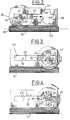
- the actuator 10 which is shown in Figure 1 essentially comprises a worm 12 which is mounted at rotation about its longitudinal axis A1 in a housing 14 of the actuator 10 and which meshes with a wheel 16 of the axle transverse A2 perpendicular to the axis A1 of the screw 12.
- the screw endless 12 is driven by an electric motor 13 but the invention can also be implemented with any type of means for driving the screw 12. This can thus be driven by a simple crank or by a flexible cable rotating motion transmission.
- the wheel 16 is guided along the direction of its axis A2 between two opposite side walls 18, 20 of the housing 14 and it is integral with an output shaft 22 which is arranged according to its axis A2 and which is integral in rotation with the wheel 16.
- the actuator 10 also includes a control pad 24 and a guide bearing 26 which are each mounted on one side of the wheel 16 on the output shaft 22.
- the control pad 24 is integral in rotation with the wheel 16 and it is received in a control light 28 arranged in one of the side walls 18 of the housing 14.
- the guide bearing 26 is rotatably mounted on the shaft 22 and it is received in a guide light 30 arranged in the other 20 of the walls side of the case.
- the light from guide 30 is a rectilinear light which extends parallel to the longitudinal direction of the screw 12. It has two opposite longitudinal edges 32 between which the bearing guide 26 is received.
- the bearing 26 has two faces longitudinal straight lines 34 which cooperate with the edges longitudinal 32 of light 30 to prevent the bearing from guide 26 to rotate in the corresponding light 30.
- the bearing 26 is thus capable of sliding longitudinally in the light 30.
- the light of control 28, in which the control shoe 24 is received has two straight sections 36 and circular sections 38 which are follow longitudinally from back to front according to the direction of the axis A1 of the worm screw 12.
- the first section 36 of the control light 28 is a straight section which extends parallel to the light of guide 30 and which also has two longitudinal edges opposites 40 with which two longitudinal faces cooperate rectilinear and parallel 42 of the control pad 24.
- the shoe 24 is capable of sliding longitudinally, in both directions, without being able to turn around the axis A2 of the output shaft 22.
- the second section 38 of the control light 28 essentially comprises a lateral edge in an arc 44 which spans more than three-quarters of a circle and in which opens the first section 36 of the control light 28.
- the diameter of the second circular section 38 of the light 28 is substantially equal to the largest dimension of the shoe 24 in a direction perpendicular to the axis A2 of the wheel 16 so that the latter can pivot around the axis A2 at inside the second section 38.
- the wheel 16 is arranged on the screw 12 so that the shoe control 24 is received in the first section 36 of the light 28, and more particularly in the end rear longitudinal 35 of the first section 36 which is opposite to its front end 37 by which it opens into the second section 38.
- the control pad 24 is then immobilized in rotation about the axis A2 by its longitudinal faces 42 which cooperate with the longitudinal edges 40 of the first section 36.
- the wheel moves longitudinally from back to front, i.e. from the left to the right considering the figures, taking with it the output shaft 22.
- the shoe command 24 leaves the first section 36, it is fully received inside the second section 38 and it is supported by a front longitudinal end against the circular edge 44 of the latter so as to prevent any translation additional towards the front of the shoe 24, and therefore of the wheel 16 and the output shaft 22.
- the rotation of the shoe 24 in the second section 38 of the control light 28 is limited by two stops 46, 48 which are arranged so as to limit the angular travel of the shoe, and therefore of the output shaft 22, in the second section 28.
- This abutment face 46 is arranged so that the bearing 41 performs a quarter turn between its positions shown in Figures 3 and 4 respectively.
- the pad 24 is then no longer capable of pivoting around the axis 32 nor to translate inside the second section 28 so that the wheel 16 is completely immobilized. It is then necessary to stop the engine 13 either by detecting the arrival of the pad 24 in this position, either by detecting a sudden variation in the torque supplied by the electric motor 13.
- the shoe 24 In this position, the shoe 24 is oriented so that its longitudinal faces 42 are oriented parallel to the longitudinal edges 40 of the first section 36 of the lumen control 28, opposite the front longitudinal end 37 of the first section 36 which opens into the second section 38.
- the shoe 24 By the action of the second stopper 48, the shoe 24 is prevented pivot around its axis A2 so that the movement of rotation of screw 12 is transformed into a movement of translation; from back to front, from the wheel 16.
- the shoe 24 tends then to engage again in the first section 38 of the control light 28 and thus continues until arrival in its initial position shown in Figure 2.
- the actuator according to the invention therefore makes it possible to use the only rotary movement of the worm, without change of direction, to cause two consecutive movements of the output shaft 22.
- FIG. 5 shows an anti-theft device for a motor vehicle steering column 50.
- Column 50 has a column shaft on which a wheel is mounted tooth 52 which is coaxial with it and which is integral therewith rotation.
- the anti-theft device essentially comprises a pinion 54, of axis A4 parallel to the axis A3 of column 50, which is mounted at rotation around its axis A4 on a sliding support 56.
- the sliding support 56 moves parallel to one direction tangent of the ring gear 52 between a disengaged position (not shown) and an engaged position shown in the Figure 5, in which the pinion 54 meshes with the crown 52.
- a device 58 for immobilizing the pinion 54 in rotation about its axis A4 is implemented.
- the immobilizer 58 which can be, for example, a multi-plate clutch torque limiter arranged along the axis A4 of the pinion 54 is controlled by by means of two cams 60 which are rotatably mounted by compared to slide 56 around a perpendicular axis A5 and concurrent with axes A3 and A4 of column 10 and of the pinion 54.
- the coach 10 allows to control with a single motor all displacements necessary to put in the state of condemnation of the lock.
- the output shaft 22 can both control the translation of the sliding support 56 and the rotation of the cams 60, using the only electric motor 13.
- the guide bearing 26 can be connected the actuator 10 to the slide 56 to ensure that the forces induced on the output shaft 22 and on the wheel 16 during of the translation are symmetrical with respect to the screw 12.
Landscapes
- Engineering & Computer Science (AREA)
- Mechanical Engineering (AREA)
- Gear Transmission (AREA)
- Steering Controls (AREA)
- Lock And Its Accessories (AREA)
Abstract
Description
L'invention concerne un actionneur, notamment pour un antivol électrique de véhicule automobile.The invention relates to an actuator, in particular for a electric vehicle anti-theft device.
L'invention concerne plus particulièrement un actionneur dans lequel un mouvement d'entrée, qui peut être fourni par exemple par un moteur électrique ou par un câble, est transformé en deux mouvements successifs d'un arbre de sortie : une translation de l'arbre suivant une direction perpendiculaire à son axe et une rotation de l'arbre autour de son axe.The invention relates more particularly to a actuator in which an input movement, which can be supplied for example by an electric motor or by a cable, is transformed into two successive movements of an output shaft: a translation of the tree in a perpendicular direction to its axis and a rotation of the tree around its axis.
Lorsqu'un mécanisme nécessite, pour son fonctionnement, deux mouvements différents, il est généralement nécessaire d'utiliser deux sources de mouvement, c'est-à-dire deux actionneurs qui sont commandés chacun pour fournir l'un des deux mouvements.When a mechanism requires, for its operation, two different movements it is usually necessary to use two sources of movement, i.e. two actuators which are each controlled to provide one of two movements.
Outre qu'il est alors nécessaire de disposer de deux actionneurs, ce qui est pénalisant en termes de coût, de poids et d'encombrement, il faut par ailleurs assurer une commande séparée de chacun de ces actionneurs, la commande des deux actionneurs n'étant par ailleurs pas forcément indépendante.Besides that it is then necessary to have two actuators, which is disadvantageous in terms of cost, weight and space, it is also necessary to ensure an order separate from each of these actuators, controlling the two actuators are also not necessarily independent.
En effet, il est souvent nécessaire que l'un des deux mouvements fournis au mécanisme précède l'autre, le second mouvement ne pouvant intervenir qu'après que le premier a cessé.Indeed, it is often necessary that one of the two movements provided to the mechanism precedes the other, the second movement can only occur after the first has ceased.
Cela est notamment le cas dans certains types d'antivol pour une colonne de direction d'un véhicule automobile.This is particularly the case in certain types of lock for a steering column of a motor vehicle.
L'invention a donc pour objet de proposer un actionneur permettant de transformer un unique mouvement d'entrée en deux mouvements successifs et de natures différentes d'un arbre de sortie de l'actionneur pour commander un mécanisme.The object of the invention is therefore to propose an actuator to transform a single entry movement into two successive and different movements of a tree actuator output to control a mechanism.
Dans ce but, l'invention propose un actionneur du type à roue et vis sans fin, caractérisé en ce que la roue comporte un patin de commande qui est fixe par rapport à la roue et qui se déplace dans une lumière de commande prévue à cet effet dans un corps fixe de l'actionneur, en ce que la lumière comporte un premier tronçon rectiligne, dans lequel le patin de commande de la roue coulisse en autorisant une translation de la roue selon une direction parallèle à l'axe de la vis et dans lequel le patin bloque toute rotation de la roue autour de son axe, et qui est prolongé par un second tronçon dans lequel le patin pivote pour autoriser la rotation de la roue autour de son axe tout en l'immobilisant en translation, et en ce que l'arbre de sortie est agencé selon l'axe de la roue et est solidaire en rotation de la roue.To this end, the invention provides an actuator of the type with wheel and worm, characterized in that the wheel has a control pad which is fixed relative to the wheel and which moves in a control light provided for this purpose in a fixed body of the actuator, in that the light comprises a first straight section, in which the control pad for the wheel slides by authorizing a translation of the wheel according to a direction parallel to the axis of the screw and in which the pad blocks any rotation of the wheel around its axis, and which is extended by a second section in which the skate pivots to allow the rotation of the wheel around its axis while immobilizing it in translation, and in that the output shaft is arranged along the axis of the wheel and is integral in rotation of the wheel.
Selon d'autres caractéristiques de l'invention :
- le second tronçon de la lumière de commande comporte un bord en arc de cercle d'axe parallèle à celui de la roue et dont le diamètre est sensiblement égal à la plus grande dimension du patin de commande dans un plan perpendiculaire à l'axe de la roue ;
- le second tronçon de la lumière de commande comporte une butée d'arrêt en rotation du patin qui limite la course angulaire du patin et de la roue quand celle-ci est sollicitée par la vis dans le sens dans lequel le patin parcourt la lumière de commande du premier vers le second tronçon, de manière à former un butée de fin de course angulaire de l'arbre de sortie
- le second tronçon de la lumière de commande comporte une butée d'arrêt en rotation du patin qui limite la course angulaire du patin et de la roue lorsque celle-ci est sollicitée par la vis dans le sens dans lequel le patin parcourt la lumière de commande du second tronçon vers le premier, de manière à déterminer une position angulaire du patin, à l'intérieur du second troncon, à partir de laquelle il est ensuite susceptible de pénétrer dans le premier tronçon ;
- la course angulaire de l'arbre de sortie qui est délimitée par les butées d'arrêt est sensiblement égale à un quart de tour ;
- la vis sans fin est entraínée en rotation autour de son axe par un moteur électrique ;
- la vis sans fin est entraínée en rotation par l'intermédiaire d'un câble ;
- la roue est montée à rotation dans un palier de guidage qui coulisse dans une lumière de guidage du corps fixe de l'actionneur, et la lumière de guidage s'étend selon une direction parallèle à celle du premier tronçon de la lumière de commande ;
- la roue et la vis sans fin sont agencées à l'intérieur d'un boítier qui comporte deux parois latérales parallèles à la direction de l'axe de la vis, l'arbre de sortie, qui est solidaire de la roue en rotation autour de leur axe commun, porte, d'un côté de la roue, le patin de commande qui est solidaire en rotation de l'arbre et qui est reçu dans la lumière de commande formée dans une des parois latérales, et, de l'autre côté de la roue, le palier de guidage qui est libre en rotation sur l'arbre de sortie et qui est reçu dans la lumière de guidage agencée dans l'autre paroi, et l'arbre comporte une extrémité axiale qui est saillante par rapport au boítier de l'actionneur et qui est reliée à un organe dont les déplacements sont commandés par l'actionneur.
- the second section of the control light has an edge in an arc of a circle parallel to that of the wheel and whose diameter is substantially equal to the largest dimension of the control pad in a plane perpendicular to the axis of the wheel;
- the second section of the control light comprises a stop in rotation of the shoe which limits the angular travel of the shoe and the wheel when the latter is stressed by the screw in the direction in which the shoe travels through the control light from the first to the second section, so as to form an angular end-of-travel stop for the output shaft
- the second section of the control light includes a stop in rotation of the shoe which limits the angular travel of the shoe and the wheel when the latter is stressed by the screw in the direction in which the shoe travels through the control light from the second section towards the first, so as to determine an angular position of the skate, inside the second section, from which it is then capable of entering the first section;
- the angular travel of the output shaft which is delimited by the stops is substantially equal to a quarter turn;
- the worm is rotated about its axis by an electric motor;
- the worm is rotated by means of a cable;
- the wheel is rotatably mounted in a guide bearing which slides in a guide light of the fixed body of the actuator, and the guide light extends in a direction parallel to that of the first section of the control light;
- the wheel and the worm are arranged inside a housing which has two side walls parallel to the direction of the axis of the screw, the output shaft, which is integral with the wheel rotating around their common axis carries, on one side of the wheel, the control shoe which is integral in rotation with the shaft and which is received in the control lumen formed in one of the side walls, and, on the other side of the wheel, the guide bearing which is free to rotate on the output shaft and which is received in the guide light arranged in the other wall, and the shaft has an axial end which is projecting relative to the housing of the actuator and which is connected to a member whose movements are controlled by the actuator.
La présente invention concerne également un antivol pour une colonne de direction de véhicule automobile, caractérisé en ce qu'il est commandé par l'arbre de sortie d'un actionneur conforme à l'une quelconque des caractéristiques précédentes.
- la colonne de direction comporte une couronne qui est solidaire d'un arbre de la colonne en rotation autour de leur axe commun, l'antivol comporte un pignon, d'axe parallèle à l'axe de la colonne et de la couronne, qui est monté à rotation sur un support coulissant, le support coulissant est susceptible d'être déplacé en translation par l'arbre de sortie de l'actionneur entre une position dégagée du pignon et une position engagée du pignon dans laquelle ce dernier engrène avec la couronne de la colonne, il est prévu des moyens d'immobilisation du pignon en rotation autour de son axe par rapport au support pour bloquer l'arbre de la colonne en rotation lorsque le pignon est en position engrenée, et les moyens d'immobilisation sont commandés par une came pivotante qui est montée à rotation sur le support et qui est solidaire de l'arbre de sortie de l'actionneur.
- the steering column comprises a crown which is integral with a shaft of the column rotating about their common axis, the anti-theft device comprises a pinion, with an axis parallel to the axis of the column and of the crown, which is rotatably mounted on a sliding support, the sliding support can be moved in translation by the output shaft of the actuator between a position released from the pinion and an engaged position of the pinion in which the latter meshes with the crown of the column, means are provided for immobilizing the pinion in rotation about its axis relative to the support to block the shaft of the column in rotation when the pinion is in the engaged position, and the immobilizing means are controlled by a pivoting cam which is rotatably mounted on the support and which is integral with the output shaft of the actuator.
D'autres caractéristiques et avantages de l'invention apparaítront à la lecture de la description détaillée qui suit pour la compréhension de laquelle on se reportera aux dessins annexés dans lesquels :
- la figure 1 est une vue en perspective éclatée de l'actionneur selon l'invention ;
- les figures 2, 3, 4 sont des schémas illustrant différentes phases de fonctionnement de l'actionneur de la figure 1 ; et
- la figure 5 est une vue schématique en perspective illustrant le principe d'un antivol de colonne de direction pour véhicule automobile destiné à être commandé par un actionneur selon l'invention.
- Figure 1 is an exploded perspective view of the actuator according to the invention;
- Figures 2, 3, 4 are diagrams illustrating different operating phases of the actuator of Figure 1; and
- Figure 5 is a schematic perspective view illustrating the principle of a steering column lock for a motor vehicle intended to be controlled by an actuator according to the invention.
L'actionneur 10 qui est représenté sur la figure 1
comporte essentiellement une vis sans fin 12 qui est montée à
rotation autour de son axe longitudinal A1 dans un boítier 14 de
l'actionneur 10 et qui engrène avec une roue 16 d'axe
transversal A2 perpendiculaire à l'axe A1 de la vis 12.The
Dans cet exemple de réalisation de l'invention, la vis
sans fin 12 est entraínée par un moteur électrique 13 mais
l'invention peut aussi être mise en oeuvre avec tout type de
moyen d'entraínement de la vis 12. Celle-ci peut ainsi être
entraínée par une simple manivelle ou par un câble flexible de
transmission de mouvement en rotation.In this exemplary embodiment of the invention, the screw
endless 12 is driven by an
La roue 16 est guidée selon la direction de son axe A2
entre deux parois latérales opposées 18, 20 du boítier 14 et
elle est solidaire d'un arbre de sortie 22 qui est agencé selon
son axe A2 et qui est solidaire en rotation de la roue 16.The
L'actionneur 10 comporte également un patin de commande
24 et un palier de guidage 26 qui sont montés chacun d'un côté
de la roue 16 sur l'arbre de sortie 22. Le patin de commande 24
est solidaire en rotation de la roue 16 et il est reçu dans une
lumière de commande 28 aménagée dans l'une des parois latérales
18 du boítier 14. Au contraire, le palier de guidage 26 est
monté libre à rotation sur l'arbre 22 et il est reçu dans une
lumière de guidage 30 agencée dans l'autre 20 des parois
latérales du boítier.The
Comme on peut le voir sur la figure 1, la lumière de
guidage 30 est une lumière rectiligne qui s'étend parallèlement
à la direction longitudinale de la vis 12. Elle comporte deux
bords longitudinaux opposés 32 entre lesquels le palier de
guidage 26 est reçu. Le palier 26 comporte deux faces
rectilignes longitudinales 34 qui coopèrent avec les bords
longitudinaux 32 de la lumière 30 pour empêcher le palier de
guidage 26 de tourner dans la lumière correspondante 30. Le
palier 26 est ainsi susceptible de coulisser longitudinalement
dans la lumière 30. As can be seen in Figure 1, the light from
Conformément à un aspect de l'invention, la lumière de
commande 28, dans laquelle est reçu le patin de commande 24,
comporte deux tronçons rectiligne 36 et circulaire 38 qui se
succèdent longitudinalement d'arrière en avant selon la
direction de l'axe A1 de la vis sans fin 12.In accordance with one aspect of the invention, the light of
Le premier troncon 36 de la lumière de commande 28 est
un tronçon rectiligne qui s'étend parallèlement à la lumière de
guidage 30 et qui comporte lui aussi deux bords longitudinaux
opposés 40 avec lesquels coopèrent deux faces longitudinales
rectilignes et parallèles 42 du patin de commande 24. Dans ce
premier tronçon, le patin 24 est susceptible de coulisser
longitudinalement, dans les deux sens, sans pouvoir tourner
autour de l'axe A2 de l'arbre de sortie 22.The
Le second tronçon 38 de la lumière de commande 28
comporte essentiellement un bord latéral en arc de cercle 44 qui
s'étend sur plus des trois quart d'un cercle et dans lequel
débouche le premier tronçon 36 de la lumière de commande 28.The
Le diamètre du second tronçon circulaire 38 de la
lumière 28 est sensiblement égal à la plus grande dimension du
patin 24 selon une direction perpendiculaire à l'axe A2 de la
roue 16 afin que ce dernier puisse pivoter autour de l'axe A2 à
l'intérieur du second tronçon 38.The diameter of the second
Le fonctionnement de l'actionneur 10 selon l'invention
sera maintenant décrit plus en détails en référence aux figures
2 à 4.The operation of the
Dans une position initiale représentée à la figure 2,
la roue 16 est agencée sur la vis 12 de telle sorte que le patin
de commande 24 est reçu dans le premier tronçon 36 de la lumière
de commande 28, et plus particulièrement dans l'extrémité
longitudinale arrière 35 du premier tronçon 36 qui est opposée à
son extrémité avant 37 par laquelle il débouche dans le second
tronçon 38. Le patin de commande 24 est alors immobilisé en
rotation autour de l'axe A2 par ses faces longitudinales 42 qui
coopèrent avec les bords longitudinaux 40 du premier tronçon 36.In an initial position shown in Figure 2,
the
De la sorte, lorsque le moteur électrique 13 entraíne
la vis sans fin 12 en rotation autour de son axe A1, la roue 16,
qui engrène avec la vis 12, ne peut tourner autour de son axe et
elle est donc commandée en translation selon la direction
longitudinale de la vis 12. La roue 16 est alors guidée de
chaque côté d'une part par le patin de commande 24 et d'autre
part par le palier de guidage 26, qui coulissent respectivement
dans leur lumière correspondante de commande 28 et de guidage
30.So, when the
Ainsi, quand le patin de commande 24 est reçu au moins
en partie dans le premier tronçon 36, la roue se déplace
longitudinalement d'arrière en avant, c'est-à-dire de la gauche
vers la droite en considérant les figures, emmenant avec elle
l'arbre de sortie 22.Thus, when the
Selon un aspect de l'invention, lorsque le patin de
commande 24 quitte le premier tronçon 36, il est entièrement
reçu à l'intérieur du second tronçon 38 et il est en appui par
une extrémité longitudinale avant contre le bord circulaire 44
de ce dernier de manière à empêcher toute translation
supplémentaire vers l'avant du patin 24, et donc de la roue 16
et de l'arbre de sortie 22.According to one aspect of the invention, when the
Si la vis sans fin 12 continue à être entraínée dans le
même sens par le moteur 13, le patin de commande 24 ne s'oppose
alors plus à la rotation de la roue 16 et celle-ci se met à
pivoter autour de son axe A2 ainsi que cela est représenté sur
la figure 4.If the
Selon un autre aspect de l'invention, la rotation du
patin 24 dans le second tronçon 38 de la lumière de commande 28
est limitée par deux butées d'arrêt 46, 48 qui sont agencées de
manière à limiter à un quart de tour la course angulaire du
patin, et donc de l'arbre de sortie 22, dans le second tronçon
28.According to another aspect of the invention, the rotation of the
En effet, lorsque la vis sans fin 12 tourne dans le
sens dans lequel elle commande le déplacement d'arrière en avant
du premier vers le second tronçon, le patin 24 tend à tourner
dans le second tronçon 28, dans le sens des aiguilles d'une
montre en considérant la figure 4, jusqu'à ce que l'une de ses
faces longitudinales 42 arrive en appui contre une première 46
des butées d'arrêt qui délimitent le bord 44 en arc de cercle du
second tronçon 28.Indeed, when the
Cette face de butée 46 est agencée de manière que le
palier 41 effectue un quart de tour entre ses positions
représentées respectivement aux figures 3 et 4. This
Le patin 24 n'est plus alors susceptible de pivoter
autour de l'axe 32 ni de se translater à l'intérieur du second
tronçon 28 de sorte que la roue 16 se trouve totalement
immobilisée. Il est alors nécessaire d'arrêter le moteur
électrique 13 soit en ayant détecté l'arrivée du patin 24 dans
cette position, soit en détectant une variation brutale du
couple fourni par le moteur électrique 13.The
On peut ensuite ramener l'arbre de sortie 22 vers sa
position initiale représentée à la figure 2 en inversant le sens
de rotation de la vis sans fin 12.We can then bring the
En partant de la position représentée à la figure 4, le
patin 24 pivote alors dans le sens contraire des aiguilles d'une
montre en considérant cette figure, jusqu'à sa position
représentée à la figure 3 dans laquelle l'une de ses faces
longitudinales 42 arrive en appui contre la deuxième 48 des
butées d'arrêt du second tronçon 38.Starting from the position shown in Figure 4, the
Dans cette position, le patin 24 est orienté de manière
que ses faces longitudinales 42 sont orientées parallèlement aux
bords longitudinaux 40 du premier tronçon 36 de la lumière de
commande 28, en regard de l'extrémité longitudinale avant 37 du
premier tronçon 36 qui débouche dans le second tronçon 38. Par
l'action de la seconde butée d'arrêt 48, le patin 24 est empêché
de pivoter autour de son axe A2 si bien que le mouvement de
rotation de la vis 12 est transformé en un mouvement de
translation; d'arrière en avant, de la roue 16. Le patin 24 tend
alors à s'engager de nouveau dans le premier tronçon 38 de la
lumière de commande 28 et continue ainsi jusqu'à l'arrivée dans
sa position initiale représentée à la figure 2.In this position, the
L'actionneur selon l'invention permet donc d'utiliser
le seul mouvement de rotation de la vis sans fin, sans
changement de sens, pour provoquer deux mouvements consécutifs
de l'arbre de sortie 22. En inversant le mouvement de rotation
de la vis, on inverse les deux mouvements consécutifs de l'arbre
de sortie 22 pour le ramener à sa position initiale.The actuator according to the invention therefore makes it possible to use
the only rotary movement of the worm, without
change of direction, to cause two consecutive movements
of the
On a représenté de manière schématique sur la figure 5
un exemple d'application dans lequel l'actionneur 10 selon
l'invention est particulièrement utile.There is shown schematically in Figure 5
an example of application in which the
On a représenté sur la figure 5 un antivol pour une
colonne de direction 50 de véhicule automobile. La colonne 50
comporte un arbre de colonne sur lequel est montée une roue
dentée 52 qui lui est coaxiale et qui en est solidaire en
rotation. L'antivol comporte essentiellement un pignon 54, d'axe
A4 parallèle à l'axe A3 de la colonne 50, qui est monté à
rotation autour de son axe A4 sur un support coulissant 56. Le
support coulissant 56 se déplace parallèlement à une direction
tangente de la couronne dentée 52 entre une position dégagée
(non représentée) et une position engagée représentée à la
figure 5, dans laquelle le pignon 54 engrène avec la couronne
52.FIG. 5 shows an anti-theft device for a
motor
Lorsque le pignon 54 est en position dégagée, il est
libre en rotation autour de son axe A4 et l'antivol est alors
dans son état déverrouillé.When the
Pour mettre en oeuvre l'antivol, on commande le
déplacement en translation du coulisseau 56 vers la position
d'engagement du pignon 54. Lorsque les dents du pignon 54
arrivent au contact de celles de la couronne 52, le pignon 54
peut tourner sur lui-même pour permettre la poursuite du
mouvement de translation du coulisseau 56.To implement the anti-theft device, you order the
translational movement of the
Lorsque le coulisseau 56 a atteint la position dans
laquelle l'entraxe entre les axes A3, A4, respectivement de la
colonne 50 et du pignon 54, est minimal, un dispositif 58
d'immobilisation en rotation du pignon 54 autour de son axe A4
est mis en oeuvre. Le dispositif d'immobilisation 58, qui peut
être par exemple un limiteur de couple à embrayage multidisques
agencé selon l'axe A4 du pignon 54 est commandé par
l'intermédiaire de deux cames 60 qui sont montées à rotation par
rapport au coulisseau 56 autour d'un axe A5 perpendiculaire et
concourant avec les axes A3 et A4 de la colonne 10 et du pignon
54.When the
Pour la mise en oeuvre du limiteur de couple, il suffit de faire pivoter les cames 60 un quart de tour autour de leur axe de rotation A5.For the implementation of the torque limiter, it suffices to rotate the cams 60 a quarter of a turn around their axis of rotation A5.
Dans cet exemple, l'entraíneur 10 selon l'invention
permet de commander à l'aide d'un seul moteur l'ensemble des
déplacements nécessaires à la mise à l'état de condamnation de
l'antivol.In this example, the
En effet, en disposant l'actionneur 10 décrit
précédemment de telle sorte que l'axe A2 de la roue 16 coïncide
avec l'axe de rotation A5 des cames 60, l'arbre de sortie 22
peut à la fois commander la translation du support coulissant 56
et la rotation des cames 60, à l'aide du seul moteur électrique
13. Eventuellement, on peut relier le palier de guidage 26 de
l'actionneur 10 au coulisseau 56 pour faire en sorte que les
efforts induits sur l'arbre de sortie 22 et sur la roue 16 lors
de la translation soient symétriques par rapport à la vis
d'entraínement 12.Indeed, by arranging the
Avantageusement, on réalise à coup sûr et à faible coût
la nécessaire séquence des deux mouvements de translation et de
rotation qui évite que l'on ne bloque le pignon 54 en rotation
avant qu'il n'ait atteint sa position correcte d'engrènement et,
inversement, qui évite que l'on tente de dégager le pignon 54
avant de l'avoir libéré en rotation.Advantageously, it is carried out for sure and at low cost
the necessary sequence of the two movements of translation and
rotation which prevents the
Claims (11)
Applications Claiming Priority (2)
| Application Number | Priority Date | Filing Date | Title |
|---|---|---|---|
| FR9615064 | 1996-12-05 | ||
| FR9615064A FR2756896B1 (en) | 1996-12-05 | 1996-12-05 | ACTUATOR, PARTICULARLY FOR AN ELECTRICAL THEFT OF A MOTOR VEHICLE |
Publications (2)
| Publication Number | Publication Date |
|---|---|
| EP0846603A1 true EP0846603A1 (en) | 1998-06-10 |
| EP0846603B1 EP0846603B1 (en) | 2001-06-27 |
Family
ID=9498449
Family Applications (1)
| Application Number | Title | Priority Date | Filing Date |
|---|---|---|---|
| EP19970121208 Expired - Lifetime EP0846603B1 (en) | 1996-12-05 | 1997-12-03 | Actuator, in particular for a vehicle anti-theft device |
Country Status (4)
| Country | Link |
|---|---|
| EP (1) | EP0846603B1 (en) |
| DE (1) | DE69705377T2 (en) |
| ES (1) | ES2160882T3 (en) |
| FR (1) | FR2756896B1 (en) |
Cited By (3)
| Publication number | Priority date | Publication date | Assignee | Title |
|---|---|---|---|---|
| EP1078829A2 (en) * | 1999-08-26 | 2001-02-28 | METHODE ELECTRONICS, Inc. | Steering lock device with safety system |
| FR2799709A1 (en) * | 1999-10-19 | 2001-04-20 | Valeo Securite Habitacle | Anti-theft device for steering column of a car comprises a ring gear mounted on the column and a cooperating pinion driven by a wheel/perpetual screw assembly and electrical engine |
| EP2476592A1 (en) * | 2011-01-13 | 2012-07-18 | Valeo Sicherheitssysteme GmbH | Steering-wheel antitheft device for an automobile |
Families Citing this family (1)
| Publication number | Priority date | Publication date | Assignee | Title |
|---|---|---|---|---|
| DE102004001511B4 (en) * | 2004-01-09 | 2015-02-19 | Continental Automotive Gmbh | Device for locking a steering column of a motor vehicle |
Citations (3)
| Publication number | Priority date | Publication date | Assignee | Title |
|---|---|---|---|---|
| US3659377A (en) * | 1970-04-01 | 1972-05-02 | Mattel Inc | Checkout stand toy with turntable drive |
| JPH04131557A (en) * | 1990-06-07 | 1992-05-06 | Asmo Co Ltd | Shift-lock actuator |
| JPH0586761A (en) * | 1991-09-30 | 1993-04-06 | Harada Ind Co Ltd | Actuator for door lock device |
-
1996
- 1996-12-05 FR FR9615064A patent/FR2756896B1/en not_active Expired - Fee Related
-
1997
- 1997-12-03 ES ES97121208T patent/ES2160882T3/en not_active Expired - Lifetime
- 1997-12-03 EP EP19970121208 patent/EP0846603B1/en not_active Expired - Lifetime
- 1997-12-03 DE DE1997605377 patent/DE69705377T2/en not_active Expired - Fee Related
Patent Citations (3)
| Publication number | Priority date | Publication date | Assignee | Title |
|---|---|---|---|---|
| US3659377A (en) * | 1970-04-01 | 1972-05-02 | Mattel Inc | Checkout stand toy with turntable drive |
| JPH04131557A (en) * | 1990-06-07 | 1992-05-06 | Asmo Co Ltd | Shift-lock actuator |
| JPH0586761A (en) * | 1991-09-30 | 1993-04-06 | Harada Ind Co Ltd | Actuator for door lock device |
Non-Patent Citations (2)
| Title |
|---|
| PATENT ABSTRACTS OF JAPAN vol. 016, no. 395 (M - 1299) 21 August 1992 (1992-08-21) * |
| PATENT ABSTRACTS OF JAPAN vol. 017, no. 417 (M - 1457) 4 August 1993 (1993-08-04) * |
Cited By (7)
| Publication number | Priority date | Publication date | Assignee | Title |
|---|---|---|---|---|
| EP1078829A2 (en) * | 1999-08-26 | 2001-02-28 | METHODE ELECTRONICS, Inc. | Steering lock device with safety system |
| EP1078829A3 (en) * | 1999-08-26 | 2003-05-07 | METHODE ELECTRONICS, Inc. | Steering lock device with safety system |
| FR2799709A1 (en) * | 1999-10-19 | 2001-04-20 | Valeo Securite Habitacle | Anti-theft device for steering column of a car comprises a ring gear mounted on the column and a cooperating pinion driven by a wheel/perpetual screw assembly and electrical engine |
| EP2476592A1 (en) * | 2011-01-13 | 2012-07-18 | Valeo Sicherheitssysteme GmbH | Steering-wheel antitheft device for an automobile |
| WO2012095246A1 (en) * | 2011-01-13 | 2012-07-19 | Valeo Sicherheitssysteme Gmbh | Steering lock for a motor vehicle |
| CN103492239A (en) * | 2011-01-13 | 2014-01-01 | 法雷奥安全系统有限责任公司 | Steering lock for a motor vehicle |
| US9085274B2 (en) | 2011-01-13 | 2015-07-21 | Valeo Sicherheitssysteme Gmbh | Steering lock for a motor vehicle |
Also Published As
| Publication number | Publication date |
|---|---|
| FR2756896B1 (en) | 1999-01-22 |
| ES2160882T3 (en) | 2001-11-16 |
| DE69705377D1 (en) | 2001-08-02 |
| FR2756896A1 (en) | 1998-06-12 |
| EP0846603B1 (en) | 2001-06-27 |
| DE69705377T2 (en) | 2001-10-31 |
Similar Documents
| Publication | Publication Date | Title |
|---|---|---|
| EP0846603B1 (en) | Actuator, in particular for a vehicle anti-theft device | |
| EP0081025B1 (en) | Rotary servo-mechanism, particularly for a vehicle steering system | |
| FR2652318A1 (en) | EXTERIOR MIRROR FOR VEHICLE. | |
| EP0764565B1 (en) | Motorized vehicle steering lock | |
| FR2690403A1 (en) | Adjustable automobile steering column - is displaceable between fixing structure by lever connected by cable to lock | |
| EP1759076B1 (en) | Device for assisting in opening/closing an openable unit | |
| FR2970311A1 (en) | Gearbox for motor vehicle, has parking brake including immobilization mechanism with cam defining engaged position for follower when tooth of latch is inserted in recess of toothed wheel | |
| FR2769037A1 (en) | LOCKING DEVICE COMPRISING A CAM-CONTROLLED TRANSMISSION FINGER | |
| FR2523532A1 (en) | Anti-theft steering lock for motor vehicle - uses sliding sleeve with plane faces around its inner and outer walls to match corresp. faces on steering column | |
| EP1214233B1 (en) | Parking brake in particular for electric-powered motor vehicle | |
| EP2659076B1 (en) | Control device for a vehicle door locking system | |
| EP0007861B1 (en) | Adjusting device for a rear-view mirror, particularly for a vehicle | |
| FR2810422A1 (en) | Lock for motor vehicle automatic transmission has actuator moving linkage to actuate locking finger to fit between teeth on wheel mounted on drive shaft | |
| EP3848548B1 (en) | Device for provisionally locking a system for motorised manoeuvring of a device of a motor vehicle | |
| WO2008078017A1 (en) | Sector in a parking brake device | |
| FR2594876A1 (en) | LOCKING DEVICE, IN PARTICULAR ANTI-THEFT DEVICE, FOR LOCK ACTUATOR OR ELECTRIC LOCK, IN PARTICULAR FOR A DOOR LOCK OF A MOTOR VEHICLE, AND LOCK EQUIPPED WITH SUCH A DEVICE | |
| FR2806118A1 (en) | Lock actuator for motor vehicle has integral force limiter formed by circular leaf spring in gear coupling to deflect under excess loads | |
| FR2474573A1 (en) | Automobile centralised door locking system - allows easy manual unlocking and has latch for slider operated by stub of motor reduction chain | |
| WO2022128987A1 (en) | Motor vehicle steering wheel with foldable or retractable rim | |
| WO2023002016A1 (en) | Vehicle steering wheel comprising mechanisms and a control actuator | |
| FR2765910A1 (en) | CONDEMNATION-DECONDAMNATION ACTUATOR FOR A MOTOR VEHICLE DOOR LOCK, AND LOCK EQUIPPED WITH SUCH AN ACTUATOR | |
| WO2024023255A1 (en) | Shut-off device | |
| FR2775719A1 (en) | LOCKING DEVICE FOR A MOTOR VEHICLE OPENING ELEMENT HAVING A PIVOTABLE TRANSMISSION DRAWABLE IN SLIDING AND CONTROLLED BY A CAM | |
| EP0352185B1 (en) | Front and rear steering device for an automotive vehicle with four steered wheels | |
| FR3135501A1 (en) | PARKING LOCK DEVICE FOR A MOTOR VEHICLE SPEED REDUCER |
Legal Events
| Date | Code | Title | Description |
|---|---|---|---|
| PUAI | Public reference made under article 153(3) epc to a published international application that has entered the european phase |
Free format text: ORIGINAL CODE: 0009012 |
|
| AK | Designated contracting states |
Kind code of ref document: A1 Designated state(s): DE ES GB IT |
|
| AX | Request for extension of the european patent |
Free format text: AL;LT;LV;MK;RO;SI |
|
| 17P | Request for examination filed |
Effective date: 19981112 |
|
| AKX | Designation fees paid |
Free format text: DE ES GB IT |
|
| RBV | Designated contracting states (corrected) |
Designated state(s): DE ES GB IT |
|
| 17Q | First examination report despatched |
Effective date: 20000412 |
|
| GRAG | Despatch of communication of intention to grant |
Free format text: ORIGINAL CODE: EPIDOS AGRA |
|
| GRAG | Despatch of communication of intention to grant |
Free format text: ORIGINAL CODE: EPIDOS AGRA |
|
| GRAH | Despatch of communication of intention to grant a patent |
Free format text: ORIGINAL CODE: EPIDOS IGRA |
|
| GRAH | Despatch of communication of intention to grant a patent |
Free format text: ORIGINAL CODE: EPIDOS IGRA |
|
| GRAA | (expected) grant |
Free format text: ORIGINAL CODE: 0009210 |
|
| AK | Designated contracting states |
Kind code of ref document: B1 Designated state(s): DE ES GB IT |
|
| RIN1 | Information on inventor provided before grant (corrected) |
Inventor name: GARNAULT, JOEL |
|
| GBT | Gb: translation of ep patent filed (gb section 77(6)(a)/1977) |
Effective date: 20010629 |
|
| REF | Corresponds to: |
Ref document number: 69705377 Country of ref document: DE Date of ref document: 20010802 |
|
| ITF | It: translation for a ep patent filed |
Owner name: SOCIETA' ITALIANA BREVETTI S.P.A. |
|
| REG | Reference to a national code |
Ref country code: ES Ref legal event code: FG2A Ref document number: 2160882 Country of ref document: ES Kind code of ref document: T3 |
|
| REG | Reference to a national code |
Ref country code: GB Ref legal event code: IF02 |
|
| PLBE | No opposition filed within time limit |
Free format text: ORIGINAL CODE: 0009261 |
|
| STAA | Information on the status of an ep patent application or granted ep patent |
Free format text: STATUS: NO OPPOSITION FILED WITHIN TIME LIMIT |
|
| 26N | No opposition filed | ||
| PGFP | Annual fee paid to national office [announced via postgrant information from national office to epo] |
Ref country code: GB Payment date: 20041123 Year of fee payment: 8 |
|
| PGFP | Annual fee paid to national office [announced via postgrant information from national office to epo] |
Ref country code: DE Payment date: 20041206 Year of fee payment: 8 |
|
| PGFP | Annual fee paid to national office [announced via postgrant information from national office to epo] |
Ref country code: ES Payment date: 20041213 Year of fee payment: 8 |
|
| PG25 | Lapsed in a contracting state [announced via postgrant information from national office to epo] |
Ref country code: IT Free format text: LAPSE BECAUSE OF NON-PAYMENT OF DUE FEES;WARNING: LAPSES OF ITALIAN PATENTS WITH EFFECTIVE DATE BEFORE 2007 MAY HAVE OCCURRED AT ANY TIME BEFORE 2007. THE CORRECT EFFECTIVE DATE MAY BE DIFFERENT FROM THE ONE RECORDED. Effective date: 20051203 Ref country code: GB Free format text: LAPSE BECAUSE OF NON-PAYMENT OF DUE FEES Effective date: 20051203 |
|
| PG25 | Lapsed in a contracting state [announced via postgrant information from national office to epo] |
Ref country code: ES Free format text: LAPSE BECAUSE OF NON-PAYMENT OF DUE FEES Effective date: 20051205 |
|
| PG25 | Lapsed in a contracting state [announced via postgrant information from national office to epo] |
Ref country code: DE Free format text: LAPSE BECAUSE OF NON-PAYMENT OF DUE FEES Effective date: 20060701 |
|
| GBPC | Gb: european patent ceased through non-payment of renewal fee |
Effective date: 20051203 |
|
| REG | Reference to a national code |
Ref country code: ES Ref legal event code: FD2A Effective date: 20051205 |