EP0845658A2 - Dynamische Routenführungsvorrichtung - Google Patents
Dynamische Routenführungsvorrichtung Download PDFInfo
- Publication number
- EP0845658A2 EP0845658A2 EP97120948A EP97120948A EP0845658A2 EP 0845658 A2 EP0845658 A2 EP 0845658A2 EP 97120948 A EP97120948 A EP 97120948A EP 97120948 A EP97120948 A EP 97120948A EP 0845658 A2 EP0845658 A2 EP 0845658A2
- Authority
- EP
- European Patent Office
- Prior art keywords
- link
- data
- route
- destination
- control center
- Prior art date
- Legal status (The legal status is an assumption and is not a legal conclusion. Google has not performed a legal analysis and makes no representation as to the accuracy of the status listed.)
- Granted
Links
Images




Classifications
-
- G—PHYSICS
- G08—SIGNALLING
- G08G—TRAFFIC CONTROL SYSTEMS
- G08G1/00—Traffic control systems for road vehicles
- G08G1/09—Arrangements for giving variable traffic instructions
- G08G1/0962—Arrangements for giving variable traffic instructions having an indicator mounted inside the vehicle, e.g. giving voice messages
- G08G1/0968—Systems involving transmission of navigation instructions to the vehicle
- G08G1/096805—Systems involving transmission of navigation instructions to the vehicle where the transmitted instructions are used to compute a route
- G08G1/096811—Systems involving transmission of navigation instructions to the vehicle where the transmitted instructions are used to compute a route where the route is computed offboard
-
- G—PHYSICS
- G01—MEASURING; TESTING
- G01C—MEASURING DISTANCES, LEVELS OR BEARINGS; SURVEYING; NAVIGATION; GYROSCOPIC INSTRUMENTS; PHOTOGRAMMETRY OR VIDEOGRAMMETRY
- G01C21/00—Navigation; Navigational instruments not provided for in groups G01C1/00 - G01C19/00
- G01C21/26—Navigation; Navigational instruments not provided for in groups G01C1/00 - G01C19/00 specially adapted for navigation in a road network
- G01C21/34—Route searching; Route guidance
- G01C21/3453—Special cost functions, i.e. other than distance or default speed limit of road segments
- G01C21/3492—Special cost functions, i.e. other than distance or default speed limit of road segments employing speed data or traffic data, e.g. real-time or historical
-
- G—PHYSICS
- G08—SIGNALLING
- G08G—TRAFFIC CONTROL SYSTEMS
- G08G1/00—Traffic control systems for road vehicles
- G08G1/09—Arrangements for giving variable traffic instructions
- G08G1/0962—Arrangements for giving variable traffic instructions having an indicator mounted inside the vehicle, e.g. giving voice messages
- G08G1/0968—Systems involving transmission of navigation instructions to the vehicle
- G08G1/096805—Systems involving transmission of navigation instructions to the vehicle where the transmitted instructions are used to compute a route
- G08G1/096827—Systems involving transmission of navigation instructions to the vehicle where the transmitted instructions are used to compute a route where the route is computed onboard
-
- G—PHYSICS
- G08—SIGNALLING
- G08G—TRAFFIC CONTROL SYSTEMS
- G08G1/00—Traffic control systems for road vehicles
- G08G1/09—Arrangements for giving variable traffic instructions
- G08G1/0962—Arrangements for giving variable traffic instructions having an indicator mounted inside the vehicle, e.g. giving voice messages
- G08G1/0968—Systems involving transmission of navigation instructions to the vehicle
- G08G1/096833—Systems involving transmission of navigation instructions to the vehicle where different aspects are considered when computing the route
- G08G1/096844—Systems involving transmission of navigation instructions to the vehicle where different aspects are considered when computing the route where the complete route is dynamically recomputed based on new data
Definitions
- the present invention relates to a dynamic route guidance apparatus, and in particular, to a Centrally-Determined Route Guidance System (CDRGS) in which a vehicle transmits data regarding its destination to a control center, and the control center returns to the vehicle information regarding a recommended route to the destination.
- CDRGS Centrally-Determined Route Guidance System
- a route guidance system in which a vehicle transmits destination data to a road beacon, and a control center connected to the road beacon calculates a recommended route to the destination and notifies the vehicle of the route via the route beacon.
- a vehicle is also equipped with a device for searching for a route to the destination, compares a recommended route transmitted by a control center and a route found by itself, and selects the most reliable and reasonable route of the two, based on the comparison result.
- the control center can calculate a route which goes only to a position according to the destination information, such as the nearest link to the destination.
- the route obtained by the control center sometimes turns out to be a detour for the vehicle to follow, and the vehicle thus may often have to select a route found by itself, rather than a recommended route. That is, a recommended route based on a consideration of the current traffic conditions may not often be fully utilized in this system.
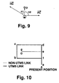
- Fig. 10 schematically shows searching processes carried out by a control center which has received destination data from a vehicle.
- a thick line represents a link controlled by the control center (a connection line between nodes corresponding to major crossings and points where road beacons are installed; hereinafter referred to as a Universal Traffic Management Systems (UTMS) link); and a thin line represents a shorter link without UTMS link coverage (hereinafter referred to as a non-UTMS link).
- UTMS Universal Traffic Management Systems
- the control center calculates a recommended route, i.e., af-fb-bc, and notifies the vehicle of this route.
- the vehicle then combines the route notified and the route found by itself into a final route, i.e., af-fb-bc-cd-de-eg. However, this route is a detour to the destination.
- the present invention has been conceived to overcome the above problems and aims to provide a dynamic route guidance apparatus which can fully utilize a recommended route sent by a control center regardless of a destination.
- a dynamic route guidance apparatus comprising memory means for storing road data held by a control center and map data; route searching means for searching for a route leading to a guiding destination by utilizing the map data; and transmitting means for transmitting to the control center the road data on a road overlapping with the route searched, as guiding destination data; wherein the control center obtains a recommended route based on the guiding destination data, and informs a vehicle of the recommended route.
- the road data is link data
- the transmitting means transmits to the control center link data regarding a link which is located nearest to the guiding destination among all links on the route searched, as the guiding destination, among all of the link data.
- the link data transmitted by the transmitting means to the control center is link data on a link directing from a present position of the vehicle to the guiding destination.
- the link data transmitted by the transmitting means to the control center is link data on a link having at least one end overlapping with the route searched.
- the above dynamic route guidance apparatus further comprises processing means for replacing a part of the route searched with a corresponding part of the recommended route transmitted by the control center, the part covering from a present position of the vehicle to an overlapping point with the road for the road data held by the control center.
- the road data is node data and link data
- the transmitting means transmits to the control center node data regarding a nearest node as the guiding destination data when all links including the nearest node as a tailing end allow further proceeding therefrom toward the guiding destination, the nearest node being located nearest to the guiding destination among all nodes on the searched route.
- the road data is node data and link data
- the transmitting means transmits to the control center link data on a link which directs opposite to a link which solely does not allow further proceeding therefrom toward the guiding destination among all links including the nearest node as a tailing end, the nearest node being located nearest to the guiding destination among all nodes on the searched route.
- the road data is node data and link data
- the transmitting means transmits to the control center link data on any of links which allow further proceeding therefrom toward the guiding destination on condition that a nearest link is located away from a nearest node by more than a predetermined value, when a plurality of links among all links including the nearest node as a tailing end do not allow further proceeding therefrom toward the guiding destination, the nearest link being located nearest to the guiding destination among all links on the searched route, the nearest node being located to the guiding destination among all nodes on the searched route.
- the road data is node data and link data
- the transmitting means transmits to the control center link data on a link which is not no thoroughfare among all links which allow further proceeding therefrom toward the guiding destination, as the guiding destination data, when a plurality of links among all links including the nearest node as a tailing end do not allow further proceeding therefrom toward the guiding destination, the nearest node being located nearest to the guiding destination among all nodes on the searched route.
- the road data is node data and link data
- the transmitting means transmits to the control center link data regarding a link which goes in a direction substantially matching with a direction from a present position of a vehicle to the guiding destination, among all links which allow further proceeding therefrom toward the guiding destination, as the guiding destination data, when a plurality of links among all links including the nearest node as a tailing end do not allow further proceeding therefrom toward the guiding destination, the nearest node being located nearest to the guiding destination among all nodes on the searched route.
- the road data is node data and link data
- the transmitting means transmits to the control center link data regarding a link with a fastest traveling speed among all links which allow further proceeding therefrom toward the guiding destination, as the guiding destination data, when a plurality of links among all links including the nearest node as a tailing end do not allow further proceeding therefrom toward the guiding destination, the nearest node being located nearest to the guiding destination among all nodes on the searched route.
- a dynamic route guidance apparatus comprising a memory for storing road data held by a control center and map data; a processor for searching for a route leading to a guiding destination by utilizing the map data; and a communicator for transmitting to the control center the road data on a road overlapping with the route searched, as guiding destination data; wherein the control center obtains a recommended route based on the guiding destination data, and informs a vehicle of the recommended route.
- the processor replaces a part of the route searched with a corresponding part of the recommended route transmitted by the control center, the part covering from a present position of a vehicle to an overlapping point with the road for the road data held by the control center.
- a vehicle does not simply transmit unique guiding destination data (a destination) to a control center, but transmits road data corresponding to respective routes searched for by the vehicle itself. This enables reduction of the likelihood that a recommended route informed to the vehicle by the control center includes detouring, so that the recommended route can be fully utilized.
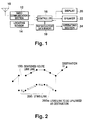
- Fig. 1 is a block diagram showing the structure of a first preferred embodiment of this invention.
- An antenna 10 and a radio communication section 12 are used for to-way data communication between a road beacon and a vehicle.
- the radio communication section 12 is connected to a controller 16 which includes a microcomputer and a memory.
- the controller 16 transmits destination data and vehicle data (such as a speed) which has been inputted via an operation section 24 to the radio communication section 12, and further to a road beacon, i.e., a control center.
- the controller 16 also displays recommended route data which has been transmitted via a road beacon on a display 20, or outputs as audio via a speaker 22.
- a display 20 can also act as an operation section 24.
- a locating sensor 14 which comprises a global positioning system (GPS) sensor, a wheel speed sensor, or a gyro sensor, locates the present position of a vehicle, and supplies data thereon to the controller 16.
- the map data memory 18 is also loaded with UTMS link data and UTMS node data, which are road link data controlled by a control center, and positional relationships between map data links and UTMS links. Respective map data links and UTMS links are given identification numbers, and the positional relationship between a map link and an UTMS link both representing the same area, is expressed with an overlap flag 1.
- An example of a correspondence table is shown below. Searched route link number Overlap flag Corresponding UTMS link number 123455 0 - 123456 1 567889 123457 1 567890 123458 0 - . . . . . . .
- both ends of a map data link and those of its corresponding UTMS link are not necessarily matched with each other.
- that UTMS link is considered to be a corresponding UTMS link to the map data link, and an overlap flag 1 is set to represent their relationship.
- a user seeking an optimum route to a destination inputs data regarding a destination via the operation section 24.
- a destination may be defined using any desired method, such as by inputting its name or coordinate points.
- the inputted destination data is sent to the controller 16, which then searches for a route (a searched route) from the present position to the destination, referring to the map data stored in the map data memory 18, using a Dijkstra method, Nicholson method, or suchlike. After a searched route has been determined, the controller 16 selects a UTMS link which is located on the searched route and is nearest to the destination, and supplies data thereon via the radio communication section 12 to the control center (up-link).
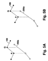
- Fig. 2 shows a searched route and a UTMS link to be up-linked.
- the route 100 is obtained by the controller 16 through a search based on the map data stored in the map data memory 18, which are more detailed data than the UTMS link data.
- the route 200 is an UTMS link line corresponding to the route 100.
- UTMS links consisting of the UTMS link line 200, a UTMS link which is nearest to the destination (the nearest UTMS link) is denoted as a UTMS link 200a.
- This link 200a is informed to the control center as destination data (guiding destination data).
- UTMS link which is located nearest to the destination when viewed from the present position of a vehicle, or the nearest UTMS link, is selected as destination data from among all corresponding UTMS links, and this is informed to the control center.
- a corresponding UTMS link that runs in the direction so as to get closer to the destination should be up-linked.
- Fig. 3 shows the state of processing when map data link has more than one corresponding UTMS link. It is assumed that the searched route link line 100 consists of map data links 123455-123456-123457-123458, and that the UTMS link line 200 consists of UTMS links 561889 (444444)-567890 (444443), wherein the parenthesized numbers denote links in the direction moving away from the destination. The UTMS link line 200 overlaps with a part of the searched route link line 100.
- map data link 123457 corresponds to UTMS links 567889 and 567890, as shown in the drawing.
- the nearest link to the destination, or UTMS link 567890 should be selected as destination data and up-linked.
- an overlap flag "1" is set only to the nearest UTMS link when two or more UTMS links correspond to a single map data link, so that the UTMS link with an overlap flag 1 is up-linked.
- the control center After transmission of the thus selected destination data (guiding destination data), the control center calculates a recommended route with the minimum cost which goes from the present position of the vehicle to the up-linked UTMS link, and notifies the vehicle of the route. Cost calculation is made based on link costs (i.e., a traveling time), connection costs (e.g., infinity for no entry), and traffic condition information which the control center constantly receives (i.e., traffic jams or accidents). For instance, the cost of a link with a traffic jam is counted higher than that of other links, depending on the seriousness of the traffic jam, and the cost of a link which is closed due to construction is counted as infinite until completion of the construction. Information on a recommended route sent by the control center is supplied, via the antenna 10 and the radio communication center, to the controller 16 of the vehicle. The controller 16 combines the searched route and the recommended route into a final route, which is then displayed on the display 20.
- link costs i.e., a traveling time
- connection costs e.
- Figs. 4A, 4B, and 4C show the progress in which the controller 16 combined the above two routes.
- Fig. 4A shows a route obtained by a vehicle through a search using map data alone;
- Fig. 4B shows a recommended route with the minimum cost, obtained by the control center, the route ending with the up-linked UTMS link 200a;
- Fig. 4C shows a final guidance route obtained by combining the above two routes such that the part of the searched route from the present position to the start of the UTMS link 200a is replaced by the corresponding part of the recommended route.
- the replaced part is denoted as "a modified part" in the drawing.
- the vehicle can reliably reach the destination in a short time because the finally determined route consists of a modified part comprising an optimum route for the current traffic condition, and a not-modified part comprising the shortest route avoiding detouring.
- the UTMS link 200a which is located on the searched route 100 and nearest to the destination, preferably overlaps with the searched route 100 at least at one end.
- Figs. 5A and 5B show typical examples where one end of the UTMS link 200a overlaps with a searched route.
- the UTMS link 200a overlaps with a searched route at the node P, while in Fig. 5B it overlaps at the node Q. This is preferable because a searched route and a recommended route must be finally combined into one final route, and combining them would require a complicated calculation without such a point of overlap.
- the two routes can be combined at the points P and Q, respectively.
- a new point must be calculated at which to combine the two routes. Even though an overlapping point between an UTMS link 200a and a searched route 100 would be preferable, , the presence of an overlapping point is not absolutely necessary in this embodiment. That is, a case where a new point must be calculated for route combining may not be excluded from this embodiment, and may be acceptable depending on the situation.
- UTMS links are subjected to coverage limitation as they do not cover, for instance, express ways
- a UTMS link which is located on a searched route and nearest to the entrance of an express way may be selected as destination data and notified to the control center.
- Fig. 6 is an operation flowchart to be followed in such a case.
- a guidance route link line N from the present position of the vehicle to the destination, i.e., a searched route
- S101 a guidance route link line N from the present position of the vehicle to the destination
- a number k for specifying a link subject to the subsequent processing is set with the number of the tailing link of the link line N, or N, wherein a link specified by the number k is referred to as Link k (S102).
- Link k Link k
- the searched route does not include an express way, it is detected whether or not the overlap flag of Link k is 1 (S104). In other words, in this step it is detected whether or not Link k has a corresponding UTMS link. Note that this judgement is made beginning with a link on the destination side, since the number of the tailing link of the line N has been initially set to specify a subject link at S102.
- the overlap flag 1 of Link k is found to be 1, " a corresponding UTMS link to Link k is determined as a transmission link, or destination data to be up-linked to a road beacon and further to a control center (S105). With an overlap flag 0, on the other hand, the number k is decremented by 1 so that a link with the reduced number is then supplied to the processes at and after S103 (S106).
- a final route which consists of a recommended route transmitted by the control center for the part from the present position of the vehicle to the entrance of an express way, and a searched route for the part from the entrance of the express way to the destination.
- the nearest UTMS link on the searched route 100 has been selected as guiding destination data, and notified to a control center.
- a UTMS node which is located nearest to the destination (the nearest UTMS node) is more preferably notified as guiding destination data to a control center, depending on the situation between a searched route and UTMS links.
- guidance destination data is determined in consideration of UTMS nodes as well.
- a solid line represents UTMS links; a broken line non-UTMS links; and an area with diagonal lines a searched route from the present position of a vehicle to a destination D.
- Links AB, BE, EF, FC, EC, BI, IH, HC HG, and GC are UTMS links; nodes A, B, C, E, F, G, H, and I are UTMS nodes; and Link BC is a non-UTMS link.
- the searched route goes from the present position via UTMS nodes A, B, and C, to the destination D.
- the nearest UTMS link (Link AB in Fig. 7) is selected as guidance destination data and informed to a control center.
- UTMS node C is nearer to the destination D than UTMS link AB in the drawing, and thus more preferably notified to the control center as guidance destination data to achieve better UTMS utilization.
- a recommended route is not specified, and any of the following routes may be selected as a recommended route:
- Fig. 8 is a flowchart for the operation of the controller 16 according to this embodiment. Specifically, when a user sets a destination via the operation section 24 (S201), the nearest UTMS link to the destination is selected as guidance destination data (S202). In the drawing, guidance destination data is denoted as CDRG destination link as it is a CDRG destination. Subsequently, the number of UTMS nodes which are nearer to the destination than the CDRG destination link are counted, and whether or not the counted number, Nnum, is larger than 0 is determined (S203). In other words, whether or not there exists at least one UTMS node nearer to the destination than the CDRG destination link, is detected at this step.
- the CDRG destination link is informed to the control center, similarly to the first embodiment.
- the nearest UTMS node is referred to as Node 1
- the second nearest UTMS node is referred to as Node 2, and so on for the rest.
- Link CG when Node p is Node C, and UTMS Link GC does not allow further proceeding from Node C toward the destination due to a right turn prohibited, Link CG, or a link directing opposite to Link GC, is set as a new CDRG destination (guiding destination).
- a recommended route to Node G is obtained when Link CG is up-linked intact.
- relative positions within Link CG are preferably corrected to be 0.
- the part of a recommended route obtained with Link CG up-linked, from the present position of the vehicle to Node C may be combined with the part of a searched route from Node C to the destination so as to obtain an optimum route.
- Link k is not no thoroughfare, whether or not the direction of Link k is the same as that from the present position of the vehicle to the destination (guidance destination), is judged (S211). This judgment is made specifically by detecting whether or not an angle ⁇ formed by these two directions is less than a predetermined value ⁇ . If the angle ⁇ is equal to or larger than the predetermined value ⁇ , in other words, if these two directions are apart from each other, the proceedable UTMS link involved is not appropriate for selection as guidance destination data, and the process at S220 is carried out again to specify the next proceedable UTMS link for the above processing.
- the parameter i for a candidate link is incremented by one whereby Link k is selected as a candidate link i (S213).
- Fig. 9 shows directions from the present position of a vehicle to the destination, and of proceedable UTMS links. It is assumed that Links HC and FC in Fig. 7 are not no thoroughfare.
- Link HC alone is selected as a candidate link, wherein ⁇ 1 is the angle formed by the vector from the present position to the destination and the vector of Link HC, and ⁇ 2 is the angle formed by the same and the vector of Link FC.
- a more appropriate recommended route can be obtained because the controller 16 can select a route which allows further proceeding toward the destination, can be entered, runs closer to the direction from the present position of the vehicle to the destination, and allows the fastest traveling speed, and the control center can be notified of such a route.
- the most appropriate proceedable UTMS link is selected from among all proceedable UTMS links, on the condition that the tailing node of the nearest UTMS link on a searched link (e.g., Node B of Link AB in Fig. 7) is located away from the nearest node (e.g., Node C in Fig. 7) by more than a predetermined value.
- any proceedable UTMS link including the nearest node as a tailing end may be selected, regardless of the above separation extent.
- the angle ⁇ is compared with a predetermined value ⁇ , and the two directions involved are concluded to be substantially matched with each other when the former is found smaller than the latter.
- an UTMS link which goes in a direction closest to the direction from the present position of the vehicle to the destination, among all proceedable UTMS links may be selected (regardless of a predetermined value). That is, the state of being substantially matched with each other includes not only a state in which a directional difference is less than a predetermined value, but also in which it is the smallest among all of them.
- the nearest UTMS link may be selected as a CDRG destination (guiding destination data) and notified to the control center, rather than selecting either the nearest node or an UTMS link having the nearest node as a tailing end, because recommended routes possibly obtained with a smaller separation extent than a predetermined value, will have only a small difference from one another.
- a vehicle does not simply transmit unique destination information to a control center, but transmits road data (a link or a node) which correspond to respective routes obtained by the vehicle itself. This enables elimination of the likelihood that a recommended route from the control center includes detouring, and resultantly allows more effective use of the recommended route.
- the vehicle In order to avoid detouring, the vehicle itself searches a route to the destination, and transmits destination data on a link to the control center. The link is located nearest to the destination among all UTMS links on the searched route, the UTMS links being controlled by the control center.
- the control center calculates a recommended route which includes the notified link as a tailing link, and informs the vehicle of the route. The vehicle combines the searched route and the informed route into a final guiding route.
Landscapes
- Engineering & Computer Science (AREA)
- Radar, Positioning & Navigation (AREA)
- Remote Sensing (AREA)
- Physics & Mathematics (AREA)
- General Physics & Mathematics (AREA)
- Automation & Control Theory (AREA)
- Mathematical Physics (AREA)
- Navigation (AREA)
- Traffic Control Systems (AREA)
- Instructional Devices (AREA)
Applications Claiming Priority (6)
| Application Number | Priority Date | Filing Date | Title |
|---|---|---|---|
| JP31942596 | 1996-11-29 | ||
| JP319425/96 | 1996-11-29 | ||
| JP31942596 | 1996-11-29 | ||
| JP137029/97 | 1997-05-27 | ||
| JP13702997A JP3480242B2 (ja) | 1996-11-29 | 1997-05-27 | 動的経路案内装置 |
| JP13702997 | 1997-05-27 |
Publications (3)
| Publication Number | Publication Date |
|---|---|
| EP0845658A2 true EP0845658A2 (de) | 1998-06-03 |
| EP0845658A3 EP0845658A3 (de) | 1999-12-08 |
| EP0845658B1 EP0845658B1 (de) | 2005-02-23 |
Family
ID=26470460
Family Applications (1)
| Application Number | Title | Priority Date | Filing Date |
|---|---|---|---|
| EP97120948A Expired - Lifetime EP0845658B1 (de) | 1996-11-29 | 1997-11-28 | Dynamische Routenführungsvorrichtung |
Country Status (4)
| Country | Link |
|---|---|
| US (1) | US6098016A (de) |
| EP (1) | EP0845658B1 (de) |
| JP (1) | JP3480242B2 (de) |
| DE (1) | DE69732555T2 (de) |
Cited By (6)
| Publication number | Priority date | Publication date | Assignee | Title |
|---|---|---|---|---|
| WO2001084082A1 (de) * | 2000-04-29 | 2001-11-08 | Robert Bosch Gmbh | Navigationsverfahren und -vorrichtung |
| EP1186865A1 (de) * | 2000-09-12 | 2002-03-13 | BECKER GmbH | Verfahren zur Bestimmung einer Fahrtroute eines Fahrzeugs |
| EP2051223A1 (de) * | 2007-10-19 | 2009-04-22 | C.R.F. Societa' Consortile per Azioni | System und Verfahren zur dynamischen Navigation für ein Fahrzeug |
| EP1717555A3 (de) * | 2005-04-25 | 2010-10-06 | The Boeing Company | Datenfusion für ein fortgeschrittenes Bodentransportsystem |
| WO2008063146A3 (en) * | 2005-04-25 | 2011-09-09 | The Boeing Company | Evacuation route planning tool |
| EP3385674A4 (de) * | 2016-03-28 | 2018-12-05 | Aisin Aw Co., Ltd. | Servervorrichtung, kommunikationsendgerät, routensuchsystem und computerprogramm |
Families Citing this family (28)
| Publication number | Priority date | Publication date | Assignee | Title |
|---|---|---|---|---|
| JP3918326B2 (ja) * | 1998-10-26 | 2007-05-23 | 株式会社デンソー | 経路設定装置及びナビゲーション装置 |
| US6292743B1 (en) | 1999-01-06 | 2001-09-18 | Infogation Corporation | Mobile navigation system |
| US6993580B2 (en) * | 1999-01-25 | 2006-01-31 | Airclic Inc. | Method and system for sharing end user information on network |
| US20020129148A1 (en) * | 1999-01-25 | 2002-09-12 | Peter Ritz | Method and system for identifying traffic conditions |
| DE19904909C2 (de) * | 1999-02-06 | 2003-10-30 | Daimler Chrysler Ag | Verfahren und Vorrichtung zur Bereitstellung von Verkehrsinformationen |
| JP3589124B2 (ja) * | 1999-11-18 | 2004-11-17 | トヨタ自動車株式会社 | ナビゲーション装置 |
| US6587781B2 (en) * | 2000-08-28 | 2003-07-01 | Estimotion, Inc. | Method and system for modeling and processing vehicular traffic data and information and applying thereof |
| JP2003097960A (ja) * | 2001-09-25 | 2003-04-03 | Toyota Motor Corp | 経路決定方法、センターおよび経路案内装置 |
| US20060122846A1 (en) * | 2002-08-29 | 2006-06-08 | Jonathan Burr | Apparatus and method for providing traffic information |
| US20040044465A1 (en) * | 2002-08-29 | 2004-03-04 | Nesbitt David W. | Automated route determination based on day of route traversal |
| US8560223B2 (en) * | 2002-08-29 | 2013-10-15 | Mapquest, Inc. | Automated route determination |
| US7133771B1 (en) | 2002-08-29 | 2006-11-07 | America Online, Inc. | Automated route determination to avoid a particular maneuver |
| WO2004061394A1 (ja) * | 2002-12-27 | 2004-07-22 | Matsushita Electric Industrial Co., Ltd. | 交通情報提供システム、交通情報表現方法及び装置 |
| US7474960B1 (en) * | 2002-12-30 | 2009-01-06 | Mapquest, Inc. | Presenting a travel route |
| US7818116B1 (en) | 2002-12-30 | 2010-10-19 | Mapquest, Inc. | Presenting a travel route in a ground-based vehicle |
| US7321824B1 (en) | 2002-12-30 | 2008-01-22 | Aol Llc | Presenting a travel route using more than one presentation style |
| US9818136B1 (en) | 2003-02-05 | 2017-11-14 | Steven M. Hoffberg | System and method for determining contingent relevance |
| US7620402B2 (en) * | 2004-07-09 | 2009-11-17 | Itis Uk Limited | System and method for geographically locating a mobile device |
| EP1779300A4 (de) | 2004-07-09 | 2013-03-27 | Tegic Communications Inc | Disambiguierung von mehrdeutigen zeichen |
| CN101163940B (zh) * | 2005-04-25 | 2013-07-24 | 株式会社吉奥技术研究所 | 摄影位置分析方法 |
| US8874477B2 (en) | 2005-10-04 | 2014-10-28 | Steven Mark Hoffberg | Multifactorial optimization system and method |
| US20100076878A1 (en) * | 2006-09-12 | 2010-03-25 | Itis Holdings Plc | Apparatus and method for implementing a road pricing scheme |
| GB0901588D0 (en) | 2009-02-02 | 2009-03-11 | Itis Holdings Plc | Apparatus and methods for providing journey information |
| JPWO2012060002A1 (ja) * | 2010-11-04 | 2014-05-12 | トヨタ自動車株式会社 | 情報提供装置 |
| GB2492369B (en) | 2011-06-29 | 2014-04-02 | Itis Holdings Plc | Method and system for collecting traffic data |
| KR101465493B1 (ko) * | 2014-01-28 | 2014-11-28 | 성균관대학교산학협력단 | 차량 내비게이션 시스템 및 차량의 목적지 경로를 결정하는 방법 |
| CN111968366B (zh) * | 2020-07-27 | 2023-09-29 | 江苏量动信息科技有限公司 | 基于区块链的高速公路路径拟合方法及装置 |
| CN114419192B (zh) | 2022-01-20 | 2026-05-05 | 腾讯科技(深圳)有限公司 | 引导线的显示方法、装置、设备、介质及程序产品 |
Family Cites Families (6)
| Publication number | Priority date | Publication date | Assignee | Title |
|---|---|---|---|---|
| JP2760253B2 (ja) * | 1992-07-14 | 1998-05-28 | 住友電気工業株式会社 | 道路の動画像作成方法及びこの方法を適用した車載ナビゲーション装置 |
| DE4300927C2 (de) * | 1993-01-15 | 2000-08-10 | Andree Kang | Computergestütztes Routen-Leitsystem für Landfahrzeuge |
| JPH0727568A (ja) * | 1993-07-09 | 1995-01-27 | Zanabui Informatics:Kk | 経路誘導装置および経路探索方法 |
| JP2614979B2 (ja) * | 1993-12-27 | 1997-05-28 | 住友電気工業株式会社 | 車載用経路取得装置 |
| JP3575494B2 (ja) * | 1993-12-28 | 2004-10-13 | 住友電気工業株式会社 | 経路誘導装置 |
| DE19539641C2 (de) * | 1995-10-25 | 2000-02-17 | Daimler Chrysler Ag | Verfahren und Einrichtung zur verkehrssituationsabhängigen Fahrzeugzielführung |
-
1997
- 1997-05-27 JP JP13702997A patent/JP3480242B2/ja not_active Expired - Fee Related
- 1997-11-28 EP EP97120948A patent/EP0845658B1/de not_active Expired - Lifetime
- 1997-11-28 DE DE69732555T patent/DE69732555T2/de not_active Expired - Lifetime
- 1997-12-01 US US08/982,265 patent/US6098016A/en not_active Expired - Lifetime
Cited By (9)
| Publication number | Priority date | Publication date | Assignee | Title |
|---|---|---|---|---|
| WO2001084082A1 (de) * | 2000-04-29 | 2001-11-08 | Robert Bosch Gmbh | Navigationsverfahren und -vorrichtung |
| AU777407B2 (en) * | 2000-04-29 | 2004-10-14 | Robert Bosch Gmbh | Navigation method and device |
| EP1186865A1 (de) * | 2000-09-12 | 2002-03-13 | BECKER GmbH | Verfahren zur Bestimmung einer Fahrtroute eines Fahrzeugs |
| JP2002156240A (ja) * | 2000-09-12 | 2002-05-31 | Becker Gmbh | 自動車の走行ルートの決定方法 |
| EP1717555A3 (de) * | 2005-04-25 | 2010-10-06 | The Boeing Company | Datenfusion für ein fortgeschrittenes Bodentransportsystem |
| WO2008063146A3 (en) * | 2005-04-25 | 2011-09-09 | The Boeing Company | Evacuation route planning tool |
| EP2051223A1 (de) * | 2007-10-19 | 2009-04-22 | C.R.F. Societa' Consortile per Azioni | System und Verfahren zur dynamischen Navigation für ein Fahrzeug |
| EP3385674A4 (de) * | 2016-03-28 | 2018-12-05 | Aisin Aw Co., Ltd. | Servervorrichtung, kommunikationsendgerät, routensuchsystem und computerprogramm |
| US11237002B2 (en) | 2016-03-28 | 2022-02-01 | Aisin Corporation | Server device, communication terminal, route retrieval system, and computer program |
Also Published As
| Publication number | Publication date |
|---|---|
| US6098016A (en) | 2000-08-01 |
| DE69732555D1 (de) | 2005-03-31 |
| JP3480242B2 (ja) | 2003-12-15 |
| JPH10214400A (ja) | 1998-08-11 |
| EP0845658B1 (de) | 2005-02-23 |
| DE69732555T2 (de) | 2006-05-18 |
| EP0845658A3 (de) | 1999-12-08 |
Similar Documents
| Publication | Publication Date | Title |
|---|---|---|
| EP0845658B1 (de) | Dynamische Routenführungsvorrichtung | |
| JP3214181B2 (ja) | 車載用ナビゲーション装置 | |
| US7840348B2 (en) | Output control method of voice guidance signal in navigation system | |
| US7653484B2 (en) | Method for determining deviation of a mobile object in a navigation system from a travel route | |
| EP2051223B1 (de) | System zur dynamischen Navigation für ein Fahrzeug | |
| JPWO2004064007A1 (ja) | ナビゲーション装置および接近情報表示方法 | |
| JP4807043B2 (ja) | 経路誘導装置および方法 | |
| KR100499002B1 (ko) | 네비게이션 시스템에서의 이동체의 복귀경로 탐색방법 | |
| JP2002533688A (ja) | 移動手段のためのナビゲーション方法およびナビゲーションシステム | |
| JP3562258B2 (ja) | 車両用案内装置および車両用案内システム | |
| JP2973967B2 (ja) | 経路探索処理方法 | |
| JP2006220562A (ja) | カーナビゲーション装置 | |
| JP3883393B2 (ja) | ナビゲーションシステム及び方法及び記録媒体 | |
| KR100451439B1 (ko) | 차량용 네비게이션 시스템 및 그 제어 방법 | |
| JP2004317405A (ja) | 車載ナビゲーション装置及びナビゲーション方法 | |
| EP0880121B1 (de) | Routenführungsgerät | |
| JP2001255163A (ja) | 経路案内装置 | |
| JP2003042786A (ja) | 経路案内装置および経路案内方法 | |
| US20050234640A1 (en) | Navigation apparatus, method, and program | |
| JP3768832B2 (ja) | ナビゲーション装置及びプログラム | |
| JPH11351891A (ja) | 経路提供装置及び方法並びにシステム | |
| JP2003057056A (ja) | 経路案内システム | |
| JP2004101395A (ja) | 経路案内装置および経路案内プログラム | |
| JP4400173B2 (ja) | 車両用ナビゲーション装置 | |
| JP3440503B2 (ja) | 自動車の経路誘導装置 |
Legal Events
| Date | Code | Title | Description |
|---|---|---|---|
| PUAI | Public reference made under article 153(3) epc to a published international application that has entered the european phase |
Free format text: ORIGINAL CODE: 0009012 |
|
| 17P | Request for examination filed |
Effective date: 19971128 |
|
| AK | Designated contracting states |
Kind code of ref document: A2 Designated state(s): DE FR GB |
|
| AX | Request for extension of the european patent |
Free format text: AL;LT;LV;MK;RO;SI |
|
| PUAL | Search report despatched |
Free format text: ORIGINAL CODE: 0009013 |
|
| AK | Designated contracting states |
Kind code of ref document: A3 Designated state(s): AT BE CH DE DK ES FI FR GB GR IE IT LI LU MC NL PT SE |
|
| AX | Request for extension of the european patent |
Free format text: AL;LT;LV;MK;RO;SI |
|
| AKX | Designation fees paid |
Free format text: DE FR GB |
|
| 17Q | First examination report despatched |
Effective date: 20040109 |
|
| GRAP | Despatch of communication of intention to grant a patent |
Free format text: ORIGINAL CODE: EPIDOSNIGR1 |
|
| GRAS | Grant fee paid |
Free format text: ORIGINAL CODE: EPIDOSNIGR3 |
|
| GRAA | (expected) grant |
Free format text: ORIGINAL CODE: 0009210 |
|
| AK | Designated contracting states |
Kind code of ref document: B1 Designated state(s): DE FR GB |
|
| REG | Reference to a national code |
Ref country code: GB Ref legal event code: FG4D |
|
| REF | Corresponds to: |
Ref document number: 69732555 Country of ref document: DE Date of ref document: 20050331 Kind code of ref document: P |
|
| ET | Fr: translation filed | ||
| PLBE | No opposition filed within time limit |
Free format text: ORIGINAL CODE: 0009261 |
|
| STAA | Information on the status of an ep patent application or granted ep patent |
Free format text: STATUS: NO OPPOSITION FILED WITHIN TIME LIMIT |
|
| 26N | No opposition filed |
Effective date: 20051124 |
|
| REG | Reference to a national code |
Ref country code: GB Ref legal event code: 746 Effective date: 20130827 |
|
| REG | Reference to a national code |
Ref country code: DE Ref legal event code: R084 Ref document number: 69732555 Country of ref document: DE Effective date: 20130829 |
|
| PGFP | Annual fee paid to national office [announced via postgrant information from national office to epo] |
Ref country code: DE Payment date: 20131120 Year of fee payment: 17 Ref country code: FR Payment date: 20131108 Year of fee payment: 17 Ref country code: GB Payment date: 20131127 Year of fee payment: 17 |
|
| REG | Reference to a national code |
Ref country code: DE Ref legal event code: R119 Ref document number: 69732555 Country of ref document: DE |
|
| GBPC | Gb: european patent ceased through non-payment of renewal fee |
Effective date: 20141128 |
|
| REG | Reference to a national code |
Ref country code: FR Ref legal event code: ST Effective date: 20150731 |
|
| PG25 | Lapsed in a contracting state [announced via postgrant information from national office to epo] |
Ref country code: GB Free format text: LAPSE BECAUSE OF NON-PAYMENT OF DUE FEES Effective date: 20141128 Ref country code: DE Free format text: LAPSE BECAUSE OF NON-PAYMENT OF DUE FEES Effective date: 20150602 |
|
| PG25 | Lapsed in a contracting state [announced via postgrant information from national office to epo] |
Ref country code: FR Free format text: LAPSE BECAUSE OF NON-PAYMENT OF DUE FEES Effective date: 20141201 |