EP0845657A2 - Vorrichtung zum Messen der Deformation einer Struktur, insbesondere einer marinen Struktur - Google Patents
Vorrichtung zum Messen der Deformation einer Struktur, insbesondere einer marinen Struktur Download PDFInfo
- Publication number
- EP0845657A2 EP0845657A2 EP97120887A EP97120887A EP0845657A2 EP 0845657 A2 EP0845657 A2 EP 0845657A2 EP 97120887 A EP97120887 A EP 97120887A EP 97120887 A EP97120887 A EP 97120887A EP 0845657 A2 EP0845657 A2 EP 0845657A2
- Authority
- EP
- European Patent Office
- Prior art keywords
- signal
- receiving
- measuring units
- generating
- flexure
- Prior art date
- Legal status (The legal status is an assumption and is not a legal conclusion. Google has not performed a legal analysis and makes no representation as to the accuracy of the status listed.)
- Withdrawn
Links
Images

Classifications
-
- G—PHYSICS
- G01—MEASURING; TESTING
- G01B—MEASURING LENGTH, THICKNESS OR SIMILAR LINEAR DIMENSIONS; MEASURING ANGLES; MEASURING AREAS; MEASURING IRREGULARITIES OF SURFACES OR CONTOURS
- G01B11/00—Measuring arrangements characterised by the use of optical techniques
- G01B11/16—Measuring arrangements characterised by the use of optical techniques for measuring the deformation in a solid, e.g. optical strain gauge
-
- G—PHYSICS
- G01—MEASURING; TESTING
- G01C—MEASURING DISTANCES, LEVELS OR BEARINGS; SURVEYING; NAVIGATION; GYROSCOPIC INSTRUMENTS; PHOTOGRAMMETRY OR VIDEOGRAMMETRY
- G01C15/00—Surveying instruments or accessories not provided for in groups G01C1/00 - G01C13/00
- G01C15/002—Active optical surveying means
Definitions
- the present invention relates to a device for measuring deformation of a structure.
- the present invention may be used to advantage, though not exclusively, for determining the deformation of a marine structure, to which the following description refers purely by way of example.
- Knowing the deformation to which merchant ships are subject is of vital importance for preventing accidents both at sea and during loading operations, particularly of bulk material. Similarly, in the case of naval ships, such knowledge may be used for correcting weapon firing direction and so improving firing precision.
- Known devices for determining the deformation of marine structures employ a measuring unit comprising a laser light emitter located at one end of the member and generating a light beam traveling parallel to the member; and a laser light receiver located at the opposite end of the member, facing the emitter in the traveling direction of the light beam, and generating a position signal correlated to the point of incidence of the light beam on a sensitive surface of the receiver.
- Any bending strain of the member in fact, shifts the point of incidence of the light beam on the sensitive surface of the receiver from its initial position, assumed as a reference ("zero") position of the undeformed member, to a final position correlated to the amount of deformation of the member; and the processing unit determines deformation of the member on the basis of the value of the position signal generated by the laser light receiver.
- a major drawback of known devices is that they provide solely for determining total deflection, as opposed to more complex deformation, of the structural member.
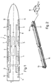
- Number 1 in Figure 1 indicates as a whole a ship having a longitudinal axis A, and comprising a device 2 for measuring deformation of ship 1 in accordance with the present invention.
- Figure 1 shows schematically only the parts of ship 1 relative to the present invention.
- respective first measuring units 5 in said pairs are located successively along a first longitudinal structural member 10 of ship 1; respective second measuring units 5 in said pairs are located successively along a second longitudinal structural member 11 on the opposite side of longitudinal axis A with respect to first longitudinal structural member 10; and each of the first measuring units 5 along first longitudinal structural member 10 is located facing a corresponding second measuring unit 5 along second longitudinal structural member 11.
- First and second longitudinal structural members 10 and 11 of ship comprise respective beam structure members located on opposite sides of longitudinal axis A and extending substantially along the whole length of ship 1, close to respective sides 7 and 8 of the ship.
- each measuring unit 5 comprises a light emitter 15 fitted adjustably to a respective portion of member 10, 11, and generating a collimated laser beam having a propagation direction parallel to the respective portion of member 10, 11 to which emitter 15 is fitted; and a light receiver 16, which is positioned facing emitter 15 in the propagation direction of the laser beam, is fitted adjustably to a respective portion of member 10, 11, at a predetermined distance from emitter 15, and generates a position signal X correlated to the point of incidence of the laser beam on a sensitive surface 17 of receiver 16.
- the corresponding receiver may be located at a much greater distance, even as much as some tens of meters, as compared with conventional optical emitters.
- emitter 15 and receiver 16 are so oriented with respect to each other that the laser beam generated by emitter 15 impinges on the exact center of sensitive surface 17 of receiver 16, and are then locked so as to be connected rigidly to member 10, 11.
- the position signal X generated by receiver 16 therefore assumes a given level, i.e. zero, which is assumed as a reference level, and any shift, caused by deformation of the respective portion of member 10, 11, in the point of incidence of the laser beam on sensitive surface 17 of receiver 16 therefore produces a variation in the level of position signal X.
- the level of position signal X and the known distance between emitter 15 and receiver 16 it is therefore possible to determine the amount of deformation of the respective portion of member 10, 11, which is generally expressed in radians or submultiples (milliradians).
- Receiver 15 may be linear or planar.
- the first type includes receivers with a substantially elongated sensitive surface 17, i.e. greater in length than in width, and generating a position signal X correlated solely to the point of incidence of the light beam along the principal dimension (length) of sensitive surface 17.
- This type of receiver requires an emitter 15 generating a substantially elliptical light beam, in which the major axis of the ellipse is perpendicular to the principal dimension of sensitive surface 17 of receiver 16.
- the second type includes receivers 16 with a substantially square sensitive surface 17, and generating a position signal X correlated to the position components of the point of incidence of the light beam, with reference to the center of sensitive surface 17 of receiver 16.
- This type of receiver 16 requires an emitter 15 generating a substantially circular light beam.
- each measuring unit 5 also comprises a processing circuit 18 for receiving and processing position signal X and generating a digital information signal I.
- each processing circuit 18 comprises a low-pass, 10 Hz cutoff-frequency, presampling filter 20 receiving the position signal X generated by respective receiver 16, and generating a filtered position signal X F ; and an analog/digital converter 21 receiving the filtered position signal X F , and generating a digital processed position signal X FD equal to the input signal sampled and quantized.
- the processed position signal X FD comprises a sequence of digital data sets, e.g. 8-bit data bytes, representing the values assumed by the filtered position signal X F during sampling.
- Each processing circuit 18 also comprises a known data framing circuit 22 receiving the data bytes of processed position signal X FD , and generating serially an information signal I comprising a sequence of data frames, each comprising a number of data bytes.
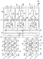
- each calculating circuit 30 receives two information signals I over LANs 25, 26, and generates a flexure gradient signal F and a torsion gradient signal T, the significance of which is explained later on.
- Each calculating circuit 30 operates on pairs of data frames, i.e. pairs of data frames generated at the same instant in time by the pair of measuring units 5 connected to calculating circuit 30. More specifically, for each pair of data frames, each calculating circuit 30 operates on pairs of data bytes, i.e. pairs of data bytes generated by sampling and quantizing at the same instant in time the pair of filtered position signals X F at the outputs of the two prefiltering filters 20 forming part of the pair of measuring units 5 connected to calculating circuit 30.
- Each calculating circuit 30 also comprises a first and a second multiplying circuit 33, 34 respectively receiving the sum signal and the difference signal, and respectively generating a first and a second intermediate signal respectively equal to the sum signal multiplied by a constant k 1 , and to the difference signal multiplied by a constant k 2 .
- constants k 1 and k 2 are conversion constants for converting the electric measuring unit (voltage), in which information signals I and the signals derived from them are expressed, into an angular measuring unit (radians) in which flexure gradient signal F and torsion gradient signal T are expressed.
- Each calculating circuit 30 also comprises a first and a second low-pass filter 35, 36 respectively receiving the first and the second intermediate signal, and respectively generating flexure gradient signal F and torsion gradient signal T respectively indicating the flexure and torsion, e.g. induced respectively by pitching and rolling of ship 1, of the portions of respective members 10, 11 to which measuring units 5 are fitted.
- Low-pass filters 35, 36 are numeric for eliminating any high-frequency variations in the data frames at their inputs, and therefore have a cutoff frequency of 3-5 Hz, depending on the environment in which device 2 according to the present invention is operated.
- Flexure and torsion gradient signals F and T each comprise a sequence of a number of data frames, in turn comprising a number of data bytes, each indicating a value of the flexure and, respectively, the torsion of the portion of member 10, 11 to which the respective measuring units are fitted.
- measuring device 2 According to the present invention, operation of the device will now be described with reference to a number of typical working conditions.
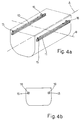
- Figures 4a and 4b respectively show a view in perspective and a front view of a portion of ship 1 in the undeformed condition.
- Rigid rolling and/or pitching of ship 1 produces no flexure or torsion of members 10, 11, so that, as shown in Figure 4b, the beams generated by emitters 15 remain in the respective zero positions, and position signals X generated by respective receivers 16 maintain the same value (zero reference) as formerly, i.e. prior to rolling and/or pitching of ship 1.
- the output of adding circuit 31 of calculating circuit 30 receiving information signals I corresponding to said position signals X presents a sum signal having value corresponding to the sum of reference value of said position signals X (i.e. zero reference), i.e. indicating zero flexure of the two respective portions of members 10, 11 during rolling and/or pitching of ship 1.
- the output of subtracting circuit 32 of calculating circuit 30 receiving information signals I corresponding to said position signals X presents a zero difference signal indicating zero torsion of the two respective portions of members 10, 11 during rolling and/or pitching of ship 1.
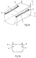
- Figures 5a, 5b show the situation in which a portion of ship 1 is subjected to "rolling" torsion, i.e. about axis A; in which case, the two portions of members 10, 11 undergo flexure in opposite directions, due to the sections fitted with receivers 16 being rotated differently as compared with the sections fitted with emitters 15.
- each emitter 15 in relation to respective receiver 16 therefore varies. More specifically, and as shown more clearly in Figure 5b, the points of incidence of the light beams on the sensitive surfaces of the two receivers 16 are shifted equally but in opposite directions, so that position signals X generated by respective receivers 16 assume the same value but of opposite sign.
- the output of adding circuit 31 of calculating circuit 30 receiving information signals I corresponding to said position signals X therefore presents a zero sum signal, whilst the output of subtracting circuit 32 presents a difference signal of a value other than zero and correlated to the amount of torsion of the corresponding portion of ship 1.
- Figures 6a, 6b show the situation in which a portion of ship 1 is subjected to purely "pitching" flexure, i.e. in a vertical plane containing axis A.
- the two portions of members 10, 11 undergo flexure in the same direction, so that the points of incidence of the light beams on the sensitive surfaces of the two receivers 16 shift equally in the same direction, and the position signals generated by receivers 16 assume the same value and sign.
- the output of subtracting circuit 32 of calculating circuit 30 receiving information signals I corresponding to said position signals X therefore presents a zero difference signal, whilst the output of adding circuit 31 presents a sum signal of a value other than zero and correlated to the amount of flexure of the corresponding portion of ship 1.
- device 2 provides for determining both flexure and torsion of any elongated structure, be it a ship, bridge or flyover, to both safeguard the structure and ensure user safety.
- Device 2 provides for determining two-dimensional deformation of ship 1 along the portions fitted with measuring units 5. Deformation of the ship along critical portions of members 10, 11 may therefore be monitored even more accurately by increasing the number of measuring units 5 along such portions.
- Device 2 according to the present invention is intrinsically highly reliable. Performance is not seriously impaired by failure of any one of measuring units 5, by virtue of the missing information being obtainable, for example, by interpolating the information provided by the adjacent measuring units 5.
Landscapes
- Physics & Mathematics (AREA)
- General Physics & Mathematics (AREA)
- Engineering & Computer Science (AREA)
- Radar, Positioning & Navigation (AREA)
- Remote Sensing (AREA)
- Length Measuring Devices By Optical Means (AREA)
- Length Measuring Devices With Unspecified Measuring Means (AREA)
- Investigating Strength Of Materials By Application Of Mechanical Stress (AREA)
- Investigating Or Analyzing Materials Using Thermal Means (AREA)
Applications Claiming Priority (2)
| Application Number | Priority Date | Filing Date | Title |
|---|---|---|---|
| ITTO960970 | 1996-11-29 | ||
| IT96TO000970A IT1289699B1 (it) | 1996-11-29 | 1996-11-29 | Dispositivo di misura di deformazioni di una struttura, in particolare una struttura navale |
Publications (2)
| Publication Number | Publication Date |
|---|---|
| EP0845657A2 true EP0845657A2 (de) | 1998-06-03 |
| EP0845657A3 EP0845657A3 (de) | 1999-03-17 |
Family
ID=11415064
Family Applications (1)
| Application Number | Title | Priority Date | Filing Date |
|---|---|---|---|
| EP97120887A Withdrawn EP0845657A3 (de) | 1996-11-29 | 1997-11-27 | Vorrichtung zum Messen der Deformation einer Struktur, insbesondere einer marinen Struktur |
Country Status (3)
| Country | Link |
|---|---|
| EP (1) | EP0845657A3 (de) |
| KR (1) | KR19980042902A (de) |
| IT (1) | IT1289699B1 (de) |
Cited By (5)
| Publication number | Priority date | Publication date | Assignee | Title |
|---|---|---|---|---|
| WO2000075605A1 (en) * | 1999-06-03 | 2000-12-14 | R. Rouvari Oy | System for measuring loadings in a structure, measuring unit and measuring sensor |
| WO2001061301A1 (en) * | 2000-02-15 | 2001-08-23 | Koivisto, Marja-Liisa | Method for determining the strain of construction |
| WO2004088285A3 (en) * | 2003-03-07 | 2004-12-23 | Boxboro Systems Llc | Optical determination of changes in the shape of an object and of the fluid flow around an object |
| ES2283159A1 (es) * | 2004-01-13 | 2007-10-16 | Miguel Luis Cabral Martin | Procedimiento de medida de la resistencia y fatiga de estructuras dinamicas, sometidas a deformacion y dispositivo de medicion para su puesta en practica. |
| CN119043928A (zh) * | 2024-10-31 | 2024-11-29 | 西安美泰航海科技有限公司 | 一种水下航行器耐压壳体形变测试系统 |
Families Citing this family (1)
| Publication number | Priority date | Publication date | Assignee | Title |
|---|---|---|---|---|
| KR101524032B1 (ko) * | 2013-08-22 | 2015-06-01 | 삼성중공업(주) | 3차원 구조물 정렬 장치 |
Family Cites Families (3)
| Publication number | Priority date | Publication date | Assignee | Title |
|---|---|---|---|---|
| DE1938901A1 (de) * | 1969-07-31 | 1971-02-11 | Boes Dr Ing Christian | Einrichtung zur statischen und dynamischen Messung von translatorischen und Drehbewegungen zweier Ebenen gegeneinander |
| DE2839531A1 (de) * | 1978-09-11 | 1980-03-20 | Krupp Gmbh | Torsionsmesseinrichtung |
| DE3475955D1 (en) * | 1983-06-21 | 1989-02-09 | Lasercheck Ltd | Position measurement by laser beam |
-
1996
- 1996-11-29 IT IT96TO000970A patent/IT1289699B1/it active IP Right Grant
-
1997
- 1997-11-27 EP EP97120887A patent/EP0845657A3/de not_active Withdrawn
- 1997-11-28 KR KR1019970064014A patent/KR19980042902A/ko not_active Withdrawn
Cited By (7)
| Publication number | Priority date | Publication date | Assignee | Title |
|---|---|---|---|---|
| WO2000075605A1 (en) * | 1999-06-03 | 2000-12-14 | R. Rouvari Oy | System for measuring loadings in a structure, measuring unit and measuring sensor |
| WO2001061301A1 (en) * | 2000-02-15 | 2001-08-23 | Koivisto, Marja-Liisa | Method for determining the strain of construction |
| WO2004088285A3 (en) * | 2003-03-07 | 2004-12-23 | Boxboro Systems Llc | Optical determination of changes in the shape of an object and of the fluid flow around an object |
| US7403294B2 (en) | 2003-03-07 | 2008-07-22 | Boxboro Systems, Llc | Optical measurement device and method |
| ES2283159A1 (es) * | 2004-01-13 | 2007-10-16 | Miguel Luis Cabral Martin | Procedimiento de medida de la resistencia y fatiga de estructuras dinamicas, sometidas a deformacion y dispositivo de medicion para su puesta en practica. |
| ES2283159B1 (es) * | 2004-01-13 | 2008-08-16 | Miguel Luis Cabral Martin | Procedimiento de medida de la resistencia y fatiga en estructuras dinamicas, sometidas a deformacion y dispositivo de medicion para su puesta en practica. |
| CN119043928A (zh) * | 2024-10-31 | 2024-11-29 | 西安美泰航海科技有限公司 | 一种水下航行器耐压壳体形变测试系统 |
Also Published As
| Publication number | Publication date |
|---|---|
| IT1289699B1 (it) | 1998-10-16 |
| EP0845657A3 (de) | 1999-03-17 |
| ITTO960970A1 (it) | 1998-05-29 |
| KR19980042902A (ko) | 1998-08-17 |
Similar Documents
| Publication | Publication Date | Title |
|---|---|---|
| FI93068C (fi) | Kytkentä häiriöiden haittavaikutusten pienentämiseksi sovitettua suodatinta käyttävissä vastaanottimissa | |
| EP0845657A2 (de) | Vorrichtung zum Messen der Deformation einer Struktur, insbesondere einer marinen Struktur | |
| JP4660113B2 (ja) | ファイバブラッググレーティング物理量計測装置 | |
| SE456190B (sv) | Forfarande att i ett fiberoptiskt transmissionssystem meta dispersionen hos den transmitterande optiska fibern | |
| GB2125560A (en) | Aircraft weight and balance system with automatic loading error correction | |
| US6396588B1 (en) | Hybrid curvature-tilt wave front sensor | |
| US4616931A (en) | Process and device for the contact free determination of the movement of an object | |
| US4297571A (en) | Focus detecting device | |
| RS63214B1 (sr) | Fiber-optička senzorska jedinica, optički merni sistem, uređaj za brojanje osovina, postupak brojanja osovina | |
| US4727258A (en) | Optoelectronic system for passive range metering | |
| JPH0328691B2 (de) | ||
| GB2087085A (en) | Force transducer with multiple measuring sections | |
| KR100237151B1 (ko) | 현수하중 스윙 변위검출기 | |
| EP0214483B1 (de) | Methode zur Entfernungsmessung in digitalen Distanzrelais | |
| RU2033625C1 (ru) | Радиолокационный приемник сложных сигналов | |
| US11674827B2 (en) | Saturation caused phase jump avoidance in DAS | |
| Naganuma et al. | Development of truly portable track geometry recording trolley and accompanying new measurement principle | |
| JP2997826B2 (ja) | マルチヘッド型光学式変位計 | |
| JPH021808A (ja) | 焦点検出装置 | |
| JP2818251B2 (ja) | 太陽センサ | |
| EP1394532A3 (de) | Messvorrichtung | |
| CN107328462B (zh) | 一种双偏振态光纤振动传感时域检测系统 | |
| EP0492580B1 (de) | Optischer Faserkreisel | |
| SU959283A2 (ru) | Устройство дл измерени модул коэффициента распространени цепи "металлические покровы кабел -земл | |
| SU1138760A1 (ru) | Способ измерени сдвига фаз |
Legal Events
| Date | Code | Title | Description |
|---|---|---|---|
| PUAI | Public reference made under article 153(3) epc to a published international application that has entered the european phase |
Free format text: ORIGINAL CODE: 0009012 |
|
| AK | Designated contracting states |
Kind code of ref document: A2 Designated state(s): BE DE DK ES FI FR GB GR IE IT MC NL PT SE |
|
| AX | Request for extension of the european patent |
Free format text: AL;LT;LV;MK;RO PAYMENT 971217;SI PAYMENT 971217 |
|
| PUAL | Search report despatched |
Free format text: ORIGINAL CODE: 0009013 |
|
| AK | Designated contracting states |
Kind code of ref document: A3 Designated state(s): AT BE CH DE DK ES FI FR GB GR IE IT LI LU MC NL PT SE |
|
| AX | Request for extension of the european patent |
Free format text: AL;LT;LV;MK;RO PAYMENT 971217;SI PAYMENT 971217 |
|
| RAP1 | Party data changed (applicant data changed or rights of an application transferred) |
Owner name: ALENIA MARCONI SYSTEMS S.P.A. |
|
| 17P | Request for examination filed |
Effective date: 19990722 |
|
| AKX | Designation fees paid |
Free format text: BE DE DK ES FI FR GB GR IE IT MC NL PT SE |
|
| AXX | Extension fees paid |
Free format text: RO PAYMENT 19971217;SI PAYMENT 19971217 |
|
| 17Q | First examination report despatched |
Effective date: 20011116 |
|
| STAA | Information on the status of an ep patent application or granted ep patent |
Free format text: STATUS: THE APPLICATION IS DEEMED TO BE WITHDRAWN |
|
| 18D | Application deemed to be withdrawn |
Effective date: 20020317 |