EP0845574B1 - Fensterrahmen mit einer in hohlen lateralen Glashalteleisten integrierten Jalousie - Google Patents
Fensterrahmen mit einer in hohlen lateralen Glashalteleisten integrierten Jalousie Download PDFInfo
- Publication number
- EP0845574B1 EP0845574B1 EP96402600A EP96402600A EP0845574B1 EP 0845574 B1 EP0845574 B1 EP 0845574B1 EP 96402600 A EP96402600 A EP 96402600A EP 96402600 A EP96402600 A EP 96402600A EP 0845574 B1 EP0845574 B1 EP 0845574B1
- Authority
- EP
- European Patent Office
- Prior art keywords
- sash
- retention
- control bar
- shutter
- blind
- Prior art date
- Legal status (The legal status is an assumption and is not a legal conclusion. Google has not performed a legal analysis and makes no representation as to the accuracy of the status listed.)
- Expired - Lifetime
Links
- 239000011324 bead Substances 0.000 title description 55
- 230000014759 maintenance of location Effects 0.000 claims 23
- 239000011521 glass Substances 0.000 description 15
- 230000036961 partial effect Effects 0.000 description 5
- 230000004888 barrier function Effects 0.000 description 2
- 230000008520 organization Effects 0.000 description 2
- 230000000717 retained effect Effects 0.000 description 2
- 108020004705 Codon Proteins 0.000 description 1
- RYGMFSIKBFXOCR-UHFFFAOYSA-N Copper Chemical compound [Cu] RYGMFSIKBFXOCR-UHFFFAOYSA-N 0.000 description 1
- 240000008042 Zea mays Species 0.000 description 1
- 239000002390 adhesive tape Substances 0.000 description 1
- 244000245420 ail Species 0.000 description 1
- 238000010009 beating Methods 0.000 description 1
- 230000007423 decrease Effects 0.000 description 1
- 239000011796 hollow space material Substances 0.000 description 1
- 238000009434 installation Methods 0.000 description 1
- 238000002955 isolation Methods 0.000 description 1
- 238000005304 joining Methods 0.000 description 1
- 230000000670 limiting effect Effects 0.000 description 1
- 238000004519 manufacturing process Methods 0.000 description 1
- 230000000873 masking effect Effects 0.000 description 1
- 239000013521 mastic Substances 0.000 description 1
- 239000000463 material Substances 0.000 description 1
- 239000002184 metal Substances 0.000 description 1
- 238000010422 painting Methods 0.000 description 1
- 230000002829 reductive effect Effects 0.000 description 1
- 230000002441 reversible effect Effects 0.000 description 1
- 238000005096 rolling process Methods 0.000 description 1
- 239000000565 sealant Substances 0.000 description 1
- 238000004904 shortening Methods 0.000 description 1
- 239000002023 wood Substances 0.000 description 1
Images
Classifications
-
- E—FIXED CONSTRUCTIONS
- E06—DOORS, WINDOWS, SHUTTERS, OR ROLLER BLINDS IN GENERAL; LADDERS
- E06B—FIXED OR MOVABLE CLOSURES FOR OPENINGS IN BUILDINGS, VEHICLES, FENCES OR LIKE ENCLOSURES IN GENERAL, e.g. DOORS, WINDOWS, BLINDS, GATES
- E06B9/00—Screening or protective devices for wall or similar openings, with or without operating or securing mechanisms; Closures of similar construction
- E06B9/24—Screens or other constructions affording protection against light, especially against sunshine; Similar screens for privacy or appearance; Slat blinds
- E06B9/26—Lamellar or like blinds, e.g. venetian blinds
- E06B9/262—Lamellar or like blinds, e.g. venetian blinds with flexibly-interconnected horizontal or vertical strips; Concertina blinds, i.e. upwardly folding flexible screens
-
- E—FIXED CONSTRUCTIONS
- E06—DOORS, WINDOWS, SHUTTERS, OR ROLLER BLINDS IN GENERAL; LADDERS
- E06B—FIXED OR MOVABLE CLOSURES FOR OPENINGS IN BUILDINGS, VEHICLES, FENCES OR LIKE ENCLOSURES IN GENERAL, e.g. DOORS, WINDOWS, BLINDS, GATES
- E06B9/00—Screening or protective devices for wall or similar openings, with or without operating or securing mechanisms; Closures of similar construction
- E06B9/24—Screens or other constructions affording protection against light, especially against sunshine; Similar screens for privacy or appearance; Slat blinds
- E06B9/26—Lamellar or like blinds, e.g. venetian blinds
- E06B9/264—Combinations of lamellar blinds with roller shutters, screen windows, windows, or double panes; Lamellar blinds with special devices
-
- E—FIXED CONSTRUCTIONS
- E06—DOORS, WINDOWS, SHUTTERS, OR ROLLER BLINDS IN GENERAL; LADDERS
- E06B—FIXED OR MOVABLE CLOSURES FOR OPENINGS IN BUILDINGS, VEHICLES, FENCES OR LIKE ENCLOSURES IN GENERAL, e.g. DOORS, WINDOWS, BLINDS, GATES
- E06B9/00—Screening or protective devices for wall or similar openings, with or without operating or securing mechanisms; Closures of similar construction
- E06B9/56—Operating, guiding or securing devices or arrangements for roll-type closures; Spring drums; Tape drums; Counterweighting arrangements therefor
- E06B9/58—Guiding devices
-
- E—FIXED CONSTRUCTIONS
- E06—DOORS, WINDOWS, SHUTTERS, OR ROLLER BLINDS IN GENERAL; LADDERS
- E06B—FIXED OR MOVABLE CLOSURES FOR OPENINGS IN BUILDINGS, VEHICLES, FENCES OR LIKE ENCLOSURES IN GENERAL, e.g. DOORS, WINDOWS, BLINDS, GATES
- E06B9/00—Screening or protective devices for wall or similar openings, with or without operating or securing mechanisms; Closures of similar construction
- E06B9/24—Screens or other constructions affording protection against light, especially against sunshine; Similar screens for privacy or appearance; Slat blinds
- E06B9/26—Lamellar or like blinds, e.g. venetian blinds
- E06B9/262—Lamellar or like blinds, e.g. venetian blinds with flexibly-interconnected horizontal or vertical strips; Concertina blinds, i.e. upwardly folding flexible screens
- E06B2009/2625—Pleated screens, e.g. concertina- or accordion-like
Definitions
- the awning apron cannot be wider than the distance between two glazing beads vertical opposite, unless it is placed in projection on the chassis.
- the blind When the blind is of the so-called "pleated" type, it has vertical codons passing through holes arranged in the apron, near its margins, and these holes are as many passages for the crossing light, which is very annoying when looking to obscuring daylight, for example for a bedroom to sleep.
- this invention applies to a blind whose the deck is made up of several blades but only one of them is guided by rod 6-18-41.
- the ends of the bands forming a pleated apron are placed in housings that are part of the frame window itself, so you can't not, as the present invention allows, to equip an existing window by removing the original glazing beads and replacing them with the hollow glazing beads of the invention, receiving a blind.
- the total thickness of the structure is reduced to strictly necessary, because the guides are provided in glazing beads which hold the glazing.
- the present invention completely remedies disadvantages mentioned above by guaranteeing the light-tightness of the frame-blind assembly without reducing daylight.
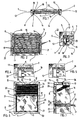
- Figure 1 is a schematic view in horizontal section of a glazed frame according to the invention.
- Figure 2 is a partial schematic view in elevation of the glass frame of figure 1.
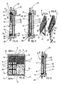
- FIGS 4 and 5 are two schematic views partial showing two variants of the invention concerning the shape of the glazing beads.
- Figure 6 is a schematic elevational view a glazed frame according to the invention and showing the organization of the cords by which we maneuver a blind, to lower it as well as to raise it.
- Figures 10 and 11 are two schematic views partial illustrations of a feature of the bar operation in two variants.
- Figure 12 is a schematic elevational view of a glazed frame according to the invention, showing the possibility that the invention gives of making a chassis glazed with cross bars.
- a glazed frame according to the invention comprises a frame formed of vertical uprights 1 and 2, of a cross upper 3 and a lower cross 4, frame which is mentioned here as being produced by assembling profiles made of wood but which, in practice, can also be made of metal or plastic.
- the uprights 1 and 2 and the crosspieces 3 and 4 have a rebate formed by a support 5 and a side 6.
- a window 7 is placed in the rebate, against the support 5, between two sides 6 located face to face.
- the depth of the rebate i.e. the distance which separates the support 5 from the front face of the corresponding amount 1 or 2 is, here, equal to the sum of the thickness glass 7 and the width of the corresponding glazing bead 8 or 9 measured from one outside face to the other of wings 13 and 14.
- the apron 16 is completely picked up, that is to say it is folded in on itself, its horizontal bands being stacked the one on top of the other, zigzagging.
- the deck 16 In extreme low position, the deck 16 is completely deployed and completely covers the glass part of the chassis, over its entire height.
- Each horizontal strip of the deck 16 is crossed two holes 18 and 19 located near the vertical edges apron 16.
- Two cords 20 and 21 are engaged and tensioned, respectively in holes 18 and in holes 19, so avoid the lateral swinging of the deck 16 and allow its manipulation by acting on any location of the maneuvering bar 17, and not only in the middle.
- the vertical margins left and right of the apron 16 are engaged in the vertical glazing beads 8 and 9, so that this apron 16 is inserted between the cores 12 located face to face of the vertical glazing beads 8 and 9 and is guided by the wings 13 and 14 of each of these glazing beads.
- this seal 22 must be very flexible because it must not create friction which would impede movements apron 16 and, even, which could damage it.
- Figure 4 shows the solution that the glazing bead has, as described above, a U-shaped profile, having a core 12 and two wings 13 and 14.
- the glass 7 is kept applied against the support 5 of the rebate by the outer face of wing 13.
- FIG. 5 shows a variant according to which the glazing bead has an L-profile having only the core 12 and a single wing 14, the wing 13 being eliminated.
- the glass 7 is kept applied against the support 5 of the rebate by the edge of the core 12.
- the surface that the window 7 is pinched between the support 5 and the glazing bead is equal to the outer width of the wing 13 multiplied by the height of the glazing bead.
- this surface is well less since it is equal to the thickness of the material forming the core 12 multiplied, of course, by the height of the glazing bead.
- the core 12 instead of presenting its simple thickness, can be fitted with a skate or have a little more thickness strong.
- Cords 20 and 21 have a special route designed to prevent the operating rod 17 from place obliquely when lowering or lowering raises to open or close the blind.
- the cord 20 is fixed by one of its ends to a lower attachment point 30 located at the base of the glazing bead 9, it extends in this paragraph 9 as far as the operating bar 17 which has, for this purpose, a lower passage aligned with a pulley 31 on which it passes and which returns it obliquely to a second pulley 32 under which it passes, then comes out of the bar maneuver 17 by an overpass thereof, to climb into glazing bead 8, pass through an eyelet 33 placed in the lower left part of the profile 15, after which it extends horizontally in the profile 15 and is fixed to one end of a spring 34.
- the cord 21 is fixed by one of its ends to a lower attachment point 35 located directly above the glazing bead 8 (therefore in symmetry with the attachment point 30), it extends in this glazing bead 8 to the bar maneuver 17 which has, for this purpose, a passage lower aligned with the pulley 32 on which it passes and which returns it obliquely to the pulley 31 under which it passes, then leaves the maneuver bar 17 by an overpass thereof, to rise in glazing bead 9, pass through an invisible eyelet in the drawing, symmetrical to the eyelet 33, and placed in the lower right part of profile 15, after which it extends horizontally in the profile 15 and is fixed to the other end of the spring 34.
- the spring 34 makes it possible to permanently ensure the tension of the cords 20 and 21 because these are fixed by one of their ends at attachment points 30 and 35 and the spring 34 biases them in tension.
- this spring 34 is optional because the tension of the cords 20 and 21 may not be essential.
- chassis is of the type called "double glazing", comprising two panes 7a and 7b separated by an isolation space 7c.
- the apron 16 is therefore easily accessible and its disassembly, for a replacement for example, is instantaneous since it suffices to remove the profile 15 and the part 55.
- the deck 16 being integral with the profile 15 and the cords 20 and 21 fixed to part 55.
- the rod 25 When the rod 25 is not used, it is concealed in the housing 27 and the operating bar 17 is behaves as if the rod 25 did not exist.
- Figure 11 shows a variant of this mode of embodiment according to which the yoke 26 is integral with a carriage (not visible in the drawing) mounted mobile by rolling pebbles or by sliding skates on guides 28 and 29 which constitute the edges of the housing 27.
- the user can thus place the yoke 26 on one side or on the other side of the maneuver bar 17, to the right or to left of the glass frame.
- the rod 25 can then be returned to its housing 27, either in the direction of arrow F1 in the figure 10. either in the opposite direction of arrow F3 in the figure 11.
- the rod 25 is housed in one of the vertical glazing beads 8 or 9 so that it does not do not stay in front of the glass part of the chassis when the operating bar 17 is in the high position.
- FIGS. 6 to 9 the case of a glazed frame having a single window 7 (or a single double glazing 7a-7b) because the apron 16 extending from a glazing bead lateral to another, there must be no abstraction between them, likely to hinder the movements of the apron 16.
- Figures 12 and 13 show that it is possible to apply the invention in case a window opens to the French and therefore has two openings.
- the apron 16 is then individual for each opening, as seen in figure 12.
- the invention also applies to the case where wishes to reverse the direction of operation of the deck, to know that this one is picked up down when it's open (it then completely clears the glass part of the chassis) and deploys from bottom to top to hide the glass part of the chassis when it reaches the upper horizontal glazing bead 10.
Landscapes
- Engineering & Computer Science (AREA)
- Structural Engineering (AREA)
- Architecture (AREA)
- Civil Engineering (AREA)
- Blinds (AREA)
- Wing Frames And Configurations (AREA)
Claims (15)
- Fensterrahmen, der der Art nach eine Falzeinfassung aufweist, die mindestens eine Glasscheibe aufnimmt, die im Falz durch seitliche, vertikale Deckleisten und durch querverlaufende, horizontale Deckleisten gehalten wird, die im oberen Teil und im unteren Teil des Rahmens gelegen sind, wobei mindestens die seitlichen Deckleisten (8 und 9) hohl sind, um einen Sitz zu bieten, der die Elemente eines Rollladens (16) aufnimmt, der beweglich vor dem verglasten Teil des Rahmens zwischen einer unsichtbaren Lage, in der er nahe der einen der Seiten der Einfassung eingeholt ist, im allgemeinen der horizontalen, oberen Seite (3), und einer Entfaltungslage angebracht ist, in der er gänzlich den genannten, verglasten Teil der Einfassung verdeckt, dadurch gekennzeichnet, daß die seitlichen Deckleisten (8, 9) einen Sitz darbieten, der die Ränder des Rollladens aufnimmt, um jeden Durchtritt von Licht zwischen diesen seitlichen Deckleisten (8, 9) und dem Rolladen (16) zu vermeiden, und dadurch gekennzeichnet, daß der Rollladen (16) mit seinem Rand an einer Betätigungsstange (17) befestigt ist und einem Führungsband (20-21) zugeordnet ist, wobei dieses Band (20-21) mit seinen beiden Enden an einer querverlaufenden, horizontalen Trennwand (11) befestigt ist, um zwei Trums darzubieten, die in den vertikalen Abdeckungen (8 und 9) hindurchlaufen, durch Umlenkeinrichtungen wie Seilscheiben (31 und 32), die die Betätigungsstange (17) trägt, umgelenkt werden, in der hohlen Betätigungsstange (17), indem sie sich kreuzen, hindurchlaufen, aus dieser wieder austreten und wieder in den vertikalen Deckleisten (8 und 9) bis zu einem Ende hindurchlaufen, in denen sie durch Umlenkeinrichtungen wie Seilscheiben (31 und 32) umgelenkt werden, um sich in der zweiten, horizontalen Deckleiste (10) zu erstrecken.
- Rahmen nach Anspruch 1, dadurch gekennzeichnet, daß die Deckleisten (8 und 9) einen U-Querschnitt haben.
- Rahmen nach Anspruch 1, dadurch gekennzeichnet, daß die Deckleisten (8 und 9) einen L-Querschnitt haben, wobei die Ränder des Rollladens (16) zwischen der Glasscheibe (7) und dem Schenkel des L (14) in Eingriff stehen, der parallel zur genannten Glasscheibe (7) verläuft.
- Rahmen nach Anspruch 1, dadurch gekennzeichnet, daß der Rollladen (16) mit seinem unteren Rand an einer Betätigungsstange (17) befestigt ist, einem Führungsband (20-21) zugeordnet ist und an einem oberen Träger (15) befestigt ist, und das Band (20-21) an einem unteren Stück (55) befestigt ist, die alle beide ausbaubar an mindestens einer der Deckleisten (8, 9, 10, 11) befestigt sind.
- Rahmen nach Anspruch 1, dadurch gekennzeichnet, daß der Rollladen (16) mit seinem unteren Rand an der Betätigungsstange (17) befestigt ist, das Band (20-21) mit seinen beiden Enden an der Deckleiste (11) befestigt ist, die auf der unteren Seite des Rahmens angeordnet ist, um zwei Trums darzubieten, die in einer Höhe, die unter der der Betätigungsstange (17) liegt, in den vertikalen Deckleisten (8 und 9) hindurchlaufen, durch Umlenkeinrichtungen wie Seilscheiben (31 und 32), die die Betätigungsstange (17) trägt, umgelenkt sind, indem sie sich in der hohlen Betätigungsstange (17) überkreuzen, aus dieser wieder herauskommen und in einer Höhe über der der Betätigungsstange (17) wieder in den vertikalen Deckleisten (8 und 9) hindurchlaufen, an deren Oberseite sie durch Umlenkeinrichtungen, wie Seilscheiben (31 und 32), sie umgelenkt sind, um sich in der horizontalen Deckleiste (10) zu erstrecken, die im oberen Teil des Rahmens angeordnet ist.
- Rahmen nach einem der Ansprüche 1 bis 5, dadurch gekennzeichnet, daß die beiden Trums (20 und 21) des Bandes getrennt sind und ihre Enden, die ihren Enden, die an der Deckleiste (11) befestigt sind, entgegengesetzt sind, an den beiden Enden eines elastischen, gespannten Elements, wie einer Zugfeder (34), befestigt sind, die dazu bestimmt ist, ständig die Zugspannung der beiden Trums (20 und 21) des Bandes sicherzustellen.
- Rahmen nach Anspruch 1, dadurch gekennzeichnet, daß die horizontale Deckleiste (10), die am oberen Teil des Rahmens angeordnet ist, auch einen U-Querschnitt aufweist und ein durchgehendes Profil (15) aufnimmt, an dem das obere Ende des Rollladens (16) befestigt ist.
- Rahmen nach Anspruch 1, dadurch gekennzeichnet, daß jede Deckleiste (8, 9) mit U-Querschnitt eine weiche Dichtung (22) aufnimmt, die gegen die Seele (12) des U angeordnet und elastisch zur Öffnung des U hin vorgespannt ist, das heißt, gegen den vertikalen Rand der Markise, deren Rand in der Deckleiste (8-9) in Eingriff steht.
- Rahmen nach Anspruch 1, dadurch gekennzeichnet, daß der Falz eine Tiefe hat, die im wesentlichen gleich ist der Summe aus der Dicke der Glasscheibe (7) und der Breite der Deckleiste (8-9).
- Rahmen nach Anspruch 1, dadurch gekennzeichnet, daß der Falz eine Breite hat, die im wesentlichen gleich der einer Deckleiste (8-9) ist.
- Rahmen nach Anspruch 1, dadurch gekennzeichnet, daß die Betätigungsstange (17) einen Stiel (25) hat, der imstande ist, sich im wesentlichen senkrecht zu ihr zu erstrecken.
- Rahmen nach Anspruch 11, dadurch gekennzeichnet, daß der Stiel (25) schwenkbar zwischen einer wirksamen Lage, in der er sich im wesentlichen senkrecht zur Betätigungsstange (17) erstreckt, und einer unwirksamen Lage angebracht ist, in der er sich in einer Längsaufnahme (27) der Betätigungsstange (17) befindet.
- Rahmen nach Anspruch 11, dadurch gekennzeichnet, daß der Stiel (25) längs der Betätigungsstange (17) beweglich angebracht ist.
- Rahmen nach Anspruch 1, dadurch gekennzeichnet, daß der Stiel (25) in einer der vertikalen Deckleisten (8-9) aufgenommen ist.
- Rahmen nach einem der Ansprüche 1 bis 14, dadurch gekennzeichnet, daß der Rollladen (16) der eine der Art nach "gefaltete" Markise ist, das heißt, aus einem Rollladen zusammengesetzt ist, der mit horizontalen Falten gekennzeichnet ist.
Priority Applications (3)
| Application Number | Priority Date | Filing Date | Title |
|---|---|---|---|
| AT96402600T ATE235650T1 (de) | 1996-11-29 | 1996-11-29 | Fensterrahmen mit einer in hohlen lateralen glashalteleisten integrierten jalousie |
| DE69626989T DE69626989T2 (de) | 1996-11-29 | 1996-11-29 | Fensterrahmen mit einer in hohlen lateralen Glashalteleisten integrierten Jalousie |
| EP96402600A EP0845574B1 (de) | 1996-11-29 | 1996-11-29 | Fensterrahmen mit einer in hohlen lateralen Glashalteleisten integrierten Jalousie |
Applications Claiming Priority (1)
| Application Number | Priority Date | Filing Date | Title |
|---|---|---|---|
| EP96402600A EP0845574B1 (de) | 1996-11-29 | 1996-11-29 | Fensterrahmen mit einer in hohlen lateralen Glashalteleisten integrierten Jalousie |
Publications (2)
| Publication Number | Publication Date |
|---|---|
| EP0845574A1 EP0845574A1 (de) | 1998-06-03 |
| EP0845574B1 true EP0845574B1 (de) | 2003-03-26 |
Family
ID=8225331
Family Applications (1)
| Application Number | Title | Priority Date | Filing Date |
|---|---|---|---|
| EP96402600A Expired - Lifetime EP0845574B1 (de) | 1996-11-29 | 1996-11-29 | Fensterrahmen mit einer in hohlen lateralen Glashalteleisten integrierten Jalousie |
Country Status (3)
| Country | Link |
|---|---|
| EP (1) | EP0845574B1 (de) |
| AT (1) | ATE235650T1 (de) |
| DE (1) | DE69626989T2 (de) |
Families Citing this family (7)
| Publication number | Priority date | Publication date | Assignee | Title |
|---|---|---|---|---|
| NL1010426C2 (nl) * | 1998-10-29 | 2000-05-03 | Verosol Nederland Bv | Glaslat en raam voorzien van glaslat. |
| AT409784B (de) * | 2000-09-13 | 2002-11-25 | Internorm Fenster | Fenster oder tür |
| DE102008012879A1 (de) * | 2008-02-27 | 2009-09-03 | Dieter Knauer | Abdeckeinrichtung für Flächen oder für Fenster, Türen od. dgl. Öffnungen |
| DE102016009101A1 (de) * | 2016-07-27 | 2018-02-01 | Sapa As | Sonnenschutzeinrichtung |
| CN109025764A (zh) * | 2018-10-24 | 2018-12-18 | 江苏赛迪乐节能科技有限公司 | 带配重的单边操控中空玻璃内置百叶窗 |
| CN110712502A (zh) * | 2019-11-19 | 2020-01-21 | 徐州麦芒汽车科技有限公司 | 一种具有防强光功能的汽车车窗 |
| CN118815345B (zh) * | 2024-09-12 | 2024-11-29 | 湖南精金玻璃有限公司 | 一种可拆卸式内置百叶中空玻璃 |
Family Cites Families (3)
| Publication number | Priority date | Publication date | Assignee | Title |
|---|---|---|---|---|
| FR1264939A (fr) | 1960-08-11 | 1961-06-23 | Koller Metallbau Ag | Châssis pour fenêtres et portes |
| DE1254330B (de) | 1960-09-23 | 1967-11-16 | Accordo Blinds Ltd | Fensterrahmen mit Faltjalousie |
| GB979683A (de) | 1962-01-24 | 1965-01-06 | Le Chassis Metallique Belge "Chamebel" Societe Anonyme |
-
1996
- 1996-11-29 AT AT96402600T patent/ATE235650T1/de not_active IP Right Cessation
- 1996-11-29 DE DE69626989T patent/DE69626989T2/de not_active Expired - Fee Related
- 1996-11-29 EP EP96402600A patent/EP0845574B1/de not_active Expired - Lifetime
Also Published As
| Publication number | Publication date |
|---|---|
| ATE235650T1 (de) | 2003-04-15 |
| DE69626989T2 (de) | 2004-01-29 |
| DE69626989D1 (de) | 2003-04-30 |
| EP0845574A1 (de) | 1998-06-03 |
Similar Documents
| Publication | Publication Date | Title |
|---|---|---|
| US6189592B1 (en) | Roll up shade doubled fabric having patterns thereon | |
| AU2003201365B2 (en) | Bottom-up/top-down retractable cellular shade | |
| AU2006202910B2 (en) | Window Covering Having Roll-Up Shade Segments | |
| FR2853686A1 (fr) | Store venitien | |
| FR2561707A1 (fr) | Store venitien et mecanisme d'echelles pour celui-ci | |
| FR3053064A3 (fr) | Dispositif de couverture | |
| EP0845574B1 (de) | Fensterrahmen mit einer in hohlen lateralen Glashalteleisten integrierten Jalousie | |
| EP0207870B1 (de) | Aussenrolladen für Kippdachfenster | |
| EP0251962B1 (de) | Anordnung zum Schutz und/oder zur Dekoration von Öffnungen in Mauern, Fenstern und dergleichen | |
| FR2737531A1 (fr) | Chassis vitre equipe d'un store engage dans des parcloses laterales creuses | |
| EP3263826B1 (de) | Rollladen mit verstellbaren lamellen | |
| FR2694584A1 (fr) | Toiture à panneaux escamotables et bâtiment équipé d'une telle toiture. | |
| US20070163726A1 (en) | System, method, and apparatus for window treatment blind having overlapping slats | |
| FR2672335A1 (fr) | Store a manóoeuvre magnetique pour doubles vitrages. | |
| EP2652232A1 (de) | Rotationsmechanismus für rollladenlatten | |
| FR2702000A3 (fr) | Store pour obscurcir des ouvertures de fenêtres ou des ouvertures de bâtiments analogues. | |
| FR2753743A1 (fr) | Nouveau type de store ou article similaire | |
| FR2557915A1 (fr) | Volet perfectionne destine a faire office de persienne a lames orientables | |
| EP1619346A1 (de) | Anordnung verbundener Lamellen, Rollladenpanzer sowie Rollladen daraus | |
| BE429685A (de) | ||
| FR3071004A3 (fr) | Store enrouleur | |
| FR2898933A1 (fr) | Bloc fenetre. | |
| KR200340806Y1 (ko) | 셔터조립체 | |
| FR3027322B1 (fr) | Caisson comprenant un auvent et un pare-soleil vertical | |
| EP4530418A1 (de) | Überdeckende verschlussvorrichtung und sonnenblende für eine gebäudeöffnung |
Legal Events
| Date | Code | Title | Description |
|---|---|---|---|
| PUAI | Public reference made under article 153(3) epc to a published international application that has entered the european phase |
Free format text: ORIGINAL CODE: 0009012 |
|
| AK | Designated contracting states |
Kind code of ref document: A1 Designated state(s): AT BE CH DE DK ES FI FR GB GR IE IT LI LU MC NL PT SE |
|
| 17P | Request for examination filed |
Effective date: 19981203 |
|
| AKX | Designation fees paid |
Free format text: AT BE CH DE DK ES FI FR GB GR IE IT LI LU MC NL PT SE |
|
| RBV | Designated contracting states (corrected) |
Designated state(s): AT BE CH DE DK ES FI FR GB GR IE IT LI LU MC NL PT SE |
|
| RAP1 | Party data changed (applicant data changed or rights of an application transferred) |
Owner name: FRANCIAFLEX SA |
|
| 17Q | First examination report despatched |
Effective date: 19990426 |
|
| GRAG | Despatch of communication of intention to grant |
Free format text: ORIGINAL CODE: EPIDOS AGRA |
|
| GRAG | Despatch of communication of intention to grant |
Free format text: ORIGINAL CODE: EPIDOS AGRA |
|
| GRAH | Despatch of communication of intention to grant a patent |
Free format text: ORIGINAL CODE: EPIDOS IGRA |
|
| GRAH | Despatch of communication of intention to grant a patent |
Free format text: ORIGINAL CODE: EPIDOS IGRA |
|
| GRAA | (expected) grant |
Free format text: ORIGINAL CODE: 0009210 |
|
| AK | Designated contracting states |
Designated state(s): AT BE CH DE DK ES FI FR GB GR IE IT LI LU MC NL PT SE |
|
| PG25 | Lapsed in a contracting state [announced via postgrant information from national office to epo] |
Ref country code: NL Free format text: LAPSE BECAUSE OF FAILURE TO SUBMIT A TRANSLATION OF THE DESCRIPTION OR TO PAY THE FEE WITHIN THE PRESCRIBED TIME-LIMIT Effective date: 20030326 Ref country code: IT Free format text: LAPSE BECAUSE OF FAILURE TO SUBMIT A TRANSLATION OF THE DESCRIPTION OR TO PAY THE FEE WITHIN THE PRESCRIBED TIME-LIMIT;WARNING: LAPSES OF ITALIAN PATENTS WITH EFFECTIVE DATE BEFORE 2007 MAY HAVE OCCURRED AT ANY TIME BEFORE 2007. THE CORRECT EFFECTIVE DATE MAY BE DIFFERENT FROM THE ONE RECORDED. Effective date: 20030326 Ref country code: IE Free format text: LAPSE BECAUSE OF NON-PAYMENT OF DUE FEES Effective date: 20030326 Ref country code: GR Free format text: LAPSE BECAUSE OF FAILURE TO SUBMIT A TRANSLATION OF THE DESCRIPTION OR TO PAY THE FEE WITHIN THE PRESCRIBED TIME-LIMIT Effective date: 20030326 Ref country code: GB Free format text: LAPSE BECAUSE OF FAILURE TO SUBMIT A TRANSLATION OF THE DESCRIPTION OR TO PAY THE FEE WITHIN THE PRESCRIBED TIME-LIMIT Effective date: 20030326 Ref country code: FI Free format text: LAPSE BECAUSE OF FAILURE TO SUBMIT A TRANSLATION OF THE DESCRIPTION OR TO PAY THE FEE WITHIN THE PRESCRIBED TIME-LIMIT Effective date: 20030326 Ref country code: AT Free format text: LAPSE BECAUSE OF FAILURE TO SUBMIT A TRANSLATION OF THE DESCRIPTION OR TO PAY THE FEE WITHIN THE PRESCRIBED TIME-LIMIT Effective date: 20030326 |
|
| REG | Reference to a national code |
Ref country code: GB Ref legal event code: FG4D Free format text: NOT ENGLISH |
|
| REG | Reference to a national code |
Ref country code: CH Ref legal event code: EP |
|
| REF | Corresponds to: |
Ref document number: 69626989 Country of ref document: DE Date of ref document: 20030430 Kind code of ref document: P |
|
| REG | Reference to a national code |
Ref country code: IE Ref legal event code: FG4D Free format text: FRENCH |
|
| PG25 | Lapsed in a contracting state [announced via postgrant information from national office to epo] |
Ref country code: SE Free format text: LAPSE BECAUSE OF FAILURE TO SUBMIT A TRANSLATION OF THE DESCRIPTION OR TO PAY THE FEE WITHIN THE PRESCRIBED TIME-LIMIT Effective date: 20030626 Ref country code: PT Free format text: LAPSE BECAUSE OF FAILURE TO SUBMIT A TRANSLATION OF THE DESCRIPTION OR TO PAY THE FEE WITHIN THE PRESCRIBED TIME-LIMIT Effective date: 20030626 Ref country code: DK Free format text: LAPSE BECAUSE OF FAILURE TO SUBMIT A TRANSLATION OF THE DESCRIPTION OR TO PAY THE FEE WITHIN THE PRESCRIBED TIME-LIMIT Effective date: 20030626 |
|
| NLV1 | Nl: lapsed or annulled due to failure to fulfill the requirements of art. 29p and 29m of the patents act | ||
| GBV | Gb: ep patent (uk) treated as always having been void in accordance with gb section 77(7)/1977 [no translation filed] |
Effective date: 20030326 |
|
| PG25 | Lapsed in a contracting state [announced via postgrant information from national office to epo] |
Ref country code: ES Free format text: LAPSE BECAUSE OF FAILURE TO SUBMIT A TRANSLATION OF THE DESCRIPTION OR TO PAY THE FEE WITHIN THE PRESCRIBED TIME-LIMIT Effective date: 20030930 |
|
| REG | Reference to a national code |
Ref country code: IE Ref legal event code: FD4D Ref document number: 0845574E Country of ref document: IE |
|
| PG25 | Lapsed in a contracting state [announced via postgrant information from national office to epo] |
Ref country code: MC Free format text: LAPSE BECAUSE OF NON-PAYMENT OF DUE FEES Effective date: 20031130 Ref country code: LU Free format text: LAPSE BECAUSE OF NON-PAYMENT OF DUE FEES Effective date: 20031130 Ref country code: LI Free format text: LAPSE BECAUSE OF NON-PAYMENT OF DUE FEES Effective date: 20031130 Ref country code: CH Free format text: LAPSE BECAUSE OF NON-PAYMENT OF DUE FEES Effective date: 20031130 |
|
| PLBE | No opposition filed within time limit |
Free format text: ORIGINAL CODE: 0009261 |
|
| STAA | Information on the status of an ep patent application or granted ep patent |
Free format text: STATUS: NO OPPOSITION FILED WITHIN TIME LIMIT |
|
| 26N | No opposition filed |
Effective date: 20031230 |
|
| REG | Reference to a national code |
Ref country code: CH Ref legal event code: PL |
|
| PGFP | Annual fee paid to national office [announced via postgrant information from national office to epo] |
Ref country code: LU Payment date: 20041029 Year of fee payment: 9 |
|
| PGFP | Annual fee paid to national office [announced via postgrant information from national office to epo] |
Ref country code: BE Payment date: 20041119 Year of fee payment: 9 |
|
| PGFP | Annual fee paid to national office [announced via postgrant information from national office to epo] |
Ref country code: DE Payment date: 20041126 Year of fee payment: 9 |
|
| PG25 | Lapsed in a contracting state [announced via postgrant information from national office to epo] |
Ref country code: BE Free format text: LAPSE BECAUSE OF NON-PAYMENT OF DUE FEES Effective date: 20051130 |
|
| PG25 | Lapsed in a contracting state [announced via postgrant information from national office to epo] |
Ref country code: DE Free format text: LAPSE BECAUSE OF NON-PAYMENT OF DUE FEES Effective date: 20060601 |
|
| BERE | Be: lapsed |
Owner name: S.A. *FRANCIAFLEX Effective date: 20051130 |
|
| REG | Reference to a national code |
Ref country code: FR Ref legal event code: PLFP Year of fee payment: 20 |
|
| PGFP | Annual fee paid to national office [announced via postgrant information from national office to epo] |
Ref country code: FR Payment date: 20151119 Year of fee payment: 20 |