EP0845238B1 - Vorrichtung zur endoskopischen Diagnose und Behandlung von Gewebe - Google Patents
Vorrichtung zur endoskopischen Diagnose und Behandlung von Gewebe Download PDFInfo
- Publication number
- EP0845238B1 EP0845238B1 EP97119015A EP97119015A EP0845238B1 EP 0845238 B1 EP0845238 B1 EP 0845238B1 EP 97119015 A EP97119015 A EP 97119015A EP 97119015 A EP97119015 A EP 97119015A EP 0845238 B1 EP0845238 B1 EP 0845238B1
- Authority
- EP
- European Patent Office
- Prior art keywords
- diagnosis
- distal end
- laser
- lasers
- light
- Prior art date
- Legal status (The legal status is an assumption and is not a legal conclusion. Google has not performed a legal analysis and makes no representation as to the accuracy of the status listed.)
- Expired - Lifetime
Links
- 238000011282 treatment Methods 0.000 title claims description 26
- 238000003745 diagnosis Methods 0.000 claims description 23
- 238000011156 evaluation Methods 0.000 claims description 12
- 239000011159 matrix material Substances 0.000 claims description 5
- 230000003287 optical effect Effects 0.000 claims description 3
- 238000012327 Endoscopic diagnosis Methods 0.000 claims description 2
- 238000012277 endoscopic treatment Methods 0.000 claims description 2
- 230000015654 memory Effects 0.000 description 10
- 230000001419 dependent effect Effects 0.000 description 8
- 239000000835 fiber Substances 0.000 description 6
- 230000003211 malignant effect Effects 0.000 description 6
- 238000012545 processing Methods 0.000 description 6
- 238000002560 therapeutic procedure Methods 0.000 description 5
- 238000005516 engineering process Methods 0.000 description 4
- 238000005259 measurement Methods 0.000 description 4
- 238000000034 method Methods 0.000 description 4
- 230000035945 sensitivity Effects 0.000 description 4
- 238000010521 absorption reaction Methods 0.000 description 3
- 238000013461 design Methods 0.000 description 3
- 230000015572 biosynthetic process Effects 0.000 description 2
- 238000010276 construction Methods 0.000 description 2
- 238000010586 diagram Methods 0.000 description 2
- 230000000694 effects Effects 0.000 description 2
- 230000005284 excitation Effects 0.000 description 2
- 230000002349 favourable effect Effects 0.000 description 2
- 230000006870 function Effects 0.000 description 2
- 230000002123 temporal effect Effects 0.000 description 2
- 230000008878 coupling Effects 0.000 description 1
- 238000010168 coupling process Methods 0.000 description 1
- 238000005859 coupling reaction Methods 0.000 description 1
- 238000001514 detection method Methods 0.000 description 1
- 230000008030 elimination Effects 0.000 description 1
- 238000003379 elimination reaction Methods 0.000 description 1
- 239000004744 fabric Substances 0.000 description 1
- 238000003384 imaging method Methods 0.000 description 1
- 230000010354 integration Effects 0.000 description 1
- 230000000968 intestinal effect Effects 0.000 description 1
- 239000000463 material Substances 0.000 description 1
- 230000000737 periodic effect Effects 0.000 description 1
- 238000011160 research Methods 0.000 description 1
- 239000004065 semiconductor Substances 0.000 description 1
- 238000000926 separation method Methods 0.000 description 1
- 229910052710 silicon Inorganic materials 0.000 description 1
- 239000010703 silicon Substances 0.000 description 1
- 208000024891 symptom Diseases 0.000 description 1
- 230000036962 time dependent Effects 0.000 description 1
- 238000012549 training Methods 0.000 description 1
- 230000001960 triggered effect Effects 0.000 description 1
Images


Classifications
-
- A—HUMAN NECESSITIES
- A61—MEDICAL OR VETERINARY SCIENCE; HYGIENE
- A61B—DIAGNOSIS; SURGERY; IDENTIFICATION
- A61B1/00—Instruments for performing medical examinations of the interior of cavities or tubes of the body by visual or photographical inspection, e.g. endoscopes; Illuminating arrangements therefor
- A61B1/00064—Constructional details of the endoscope body
- A61B1/00071—Insertion part of the endoscope body
- A61B1/0008—Insertion part of the endoscope body characterised by distal tip features
- A61B1/00096—Optical elements
-
- A—HUMAN NECESSITIES
- A61—MEDICAL OR VETERINARY SCIENCE; HYGIENE
- A61B—DIAGNOSIS; SURGERY; IDENTIFICATION
- A61B1/00—Instruments for performing medical examinations of the interior of cavities or tubes of the body by visual or photographical inspection, e.g. endoscopes; Illuminating arrangements therefor
- A61B1/00163—Optical arrangements
- A61B1/00174—Optical arrangements characterised by the viewing angles
- A61B1/00179—Optical arrangements characterised by the viewing angles for off-axis viewing
-
- A—HUMAN NECESSITIES
- A61—MEDICAL OR VETERINARY SCIENCE; HYGIENE
- A61B—DIAGNOSIS; SURGERY; IDENTIFICATION
- A61B1/00—Instruments for performing medical examinations of the interior of cavities or tubes of the body by visual or photographical inspection, e.g. endoscopes; Illuminating arrangements therefor
- A61B1/06—Instruments for performing medical examinations of the interior of cavities or tubes of the body by visual or photographical inspection, e.g. endoscopes; Illuminating arrangements therefor with illuminating arrangements
- A61B1/063—Instruments for performing medical examinations of the interior of cavities or tubes of the body by visual or photographical inspection, e.g. endoscopes; Illuminating arrangements therefor with illuminating arrangements for monochromatic or narrow-band illumination
-
- A—HUMAN NECESSITIES
- A61—MEDICAL OR VETERINARY SCIENCE; HYGIENE
- A61B—DIAGNOSIS; SURGERY; IDENTIFICATION
- A61B1/00—Instruments for performing medical examinations of the interior of cavities or tubes of the body by visual or photographical inspection, e.g. endoscopes; Illuminating arrangements therefor
- A61B1/06—Instruments for performing medical examinations of the interior of cavities or tubes of the body by visual or photographical inspection, e.g. endoscopes; Illuminating arrangements therefor with illuminating arrangements
- A61B1/0638—Instruments for performing medical examinations of the interior of cavities or tubes of the body by visual or photographical inspection, e.g. endoscopes; Illuminating arrangements therefor with illuminating arrangements providing two or more wavelengths
-
- A—HUMAN NECESSITIES
- A61—MEDICAL OR VETERINARY SCIENCE; HYGIENE
- A61B—DIAGNOSIS; SURGERY; IDENTIFICATION
- A61B5/00—Measuring for diagnostic purposes; Identification of persons
- A61B5/0059—Measuring for diagnostic purposes; Identification of persons using light, e.g. diagnosis by transillumination, diascopy, fluorescence
- A61B5/0082—Measuring for diagnostic purposes; Identification of persons using light, e.g. diagnosis by transillumination, diascopy, fluorescence adapted for particular medical purposes
- A61B5/0084—Measuring for diagnostic purposes; Identification of persons using light, e.g. diagnosis by transillumination, diascopy, fluorescence adapted for particular medical purposes for introduction into the body, e.g. by catheters
-
- A—HUMAN NECESSITIES
- A61—MEDICAL OR VETERINARY SCIENCE; HYGIENE
- A61N—ELECTROTHERAPY; MAGNETOTHERAPY; RADIATION THERAPY; ULTRASOUND THERAPY
- A61N5/00—Radiation therapy
- A61N5/06—Radiation therapy using light
- A61N5/0601—Apparatus for use inside the body
Definitions
- the invention relates to a device for endoscopic diagnosis and treatment of tissue according to that specified in the preamble of claim 1 Characteristics.
- Endoscopic devices of the type mentioned at the beginning - such a device is known for example from US Pat. No. 5,413,108 - nowadays used for example in rectoscopy.
- This will make a leaner distal End section of a generally flexible endoscope over a body opening in the body in and up to the area to be diagnosed or treated led there.
- the tissue area to be diagnosed for example the intestinal wall, with at least two diagnostic lasers of different wavelengths irradiated, after which the remitted light - be it by reflection or by Fluorescence - wavelength dependent is detected.
- the receive signals are linked with each other depending on the image point by subtraction or quotient formation, whereby the topology of the tissue section to be diagnosed is switched off becomes.
- the device structure of this known from US Pat. No. 5,413,108 The arrangement is such that both the diagnostic and treatment lasers as well the receiving devices are located outside the endoscope and via light guides are connected to the distal endoscope end.
- the wavelength separation takes place via filters which are located in a disk which engages in the beam path, which can be driven by a motor.
- a disadvantage of the aforementioned devices is, in particular, the complicated one and technically complex construction. That emitted by reflection or fluorescence Light is extremely weak and must therefore be technically complex be strengthened before it can be received and evaluated. This leads to ultimately, that the diagnostic device has a comparatively low sensitivity has or does not work with the necessary reliability.
- Diagnosis and therapy often have problems with accuracy the place of diagnosis or therapy.
- the invention is based on the object to design a generic device so that on the one hand a high Accuracy or sensitivity, but on the other hand, an inexpensive and robust construction is achieved.
- the solution according to the invention sees at least one scanning device which directs the light beams of the diagnostic laser over a diagnostic field, and a photodiode as a receiving device. So it won't be at the same time entire diagnostic field is irradiated, but instead the laser beam is scanned guided over the diagnostic field in the manner of the flying spot method. This creates a point on the diagnostic field compared to the stand the technology when using a comparable diagnostic laser higher illuminance. This in turn requires a stronger remission, which is why the signal picked up by the receiving device is stronger and therefore less is complex to record and process.
- This effect is reinforced by the fact that as a receiving device for the respective diagnostic laser is not a CCD, which simultaneously the remission of the entire diagnostic field is used, but a photodiode.
- This Photodiode which has a significantly larger aperture angle compared to a CCD and thus has a much higher sensitivity, receives time seen only the remitted light or the fluorescence of the point of the diagnostic field, which is currently being irradiated by means of the scanning device.
- the image-wise evaluation takes place in the device according to the invention by means of the control and evaluation device, depending on the time, because everyone Receive signal depending on the time a certain pixel in a pixel matrix can be assigned according to the respective position of the scanning device. Furthermore, this arrangement enables the integration of an autofocus device without using additional photodiodes.
- the invention also provides for the receiving device or when using several Receiving devices these in the distal end section of the endoscopic To arrange part of the device. This can be done by fluorescence or Reflection emits light in the shortest possible way and avoiding more complex optical devices are fed to the receiving devices, so that on the otherwise usual complex amplifier can be dispensed with.
- the lighting within the distal end section from the light entry to the receiving device can usually only be done via mirror, so that a Most of this light from the receiving device or the receiving devices can be supplied. It is particularly important that the use of the usual light guides in the area between light entry and receiving device can be completely dispensed with, making the otherwise usual small Acceptance angle significantly increased and thus the coupling losses entirely can be significantly reduced.
- the device according to the invention has therefore, due to the design, a much higher sensitivity than those known from the prior art, the structure alone is considerably cheaper and simpler that the usual light amplifiers can be completely dispensed with.
- the accuracy with regard to the diagnosis and therapy site can according to the Invention can be further increased in that the beam paths of the emitted and incident light at the distal end of the device, d. H. the ray paths also matched by diagnostic and treatment lasers become.
- the merging of the beam paths is also constructive Advantages and enables a slim design of the device especially in the distal end area.
- the device according to the invention can be equipped with a diagnostic laser and a receiving device can be operated when both the diagnostic laser as well as the receiving device are used so clocked that for a specific time interval generates and receives light of a first wavelength and generates light of a second wavelength for a further time interval and is received, as described, for example, in US Pat. No. 5,413,108.
- a diagnostic laser it is preferably proposed to have at least two diagnostic lasers to provide different wavelengths and each diagnostic laser in Assign distal end portion of the device arranged receiving device. Then both diagnostic lasers can be operated simultaneously, accordingly the reception takes place, so that the electronic signal linkage an almost real-time image is always created for topology elimination.
- the evaluation is based on very different absorption / remission of the two diagnostic wavelength ranges advantageous.
- the topology of the irradiated tissue area Irradiation with two different wavelengths and a corresponding one Evaluation.
- three Diagnostic lasers of different wavelengths are provided, which are preferred cover the wavelength ranges red, green and blue. Then namely with the received signals received from the reflected light in these three wavelength ranges additionally a natural color image, for example on a monitor being represented.
- the attending physician can thus do the arithmetic Subtraction, quotient formation or other suitably formed diagnostic image also his experiences from the natural picture bring in.
- the device advantageously within the distal end portion Scanners on which the laser beams of the diagnostic laser in front of the Deflect impingement horizontally and vertically.
- the particular distraction will electronically recorded so that the diagnosis field time-dependent diagnosis points can be assigned.
- the signals of the receiving devices are correspondingly linked so that an imaging dot matrix arises, the through frequent polling, for example three times a second, as an image Monitor that can be fed regardless of the polling frequency, for example at 50 or 100 Hz can be clocked to obtain a quiet picture.
- Such Microscanners are known per se.
- microsystem technology 1994 to 1999 program as part of the future concept Information Technology
- Information Technology published by the Federal Ministry of Research and Technology - public relations from January 1994 (ISBN 3-88135-276-7), referenced there, in particular on page 81.
- These are semiconductor mirrors, which are arranged like a seesaw and electrodes on the underside have, so that a rocking movement by electromagnetic exposure to one or the other direction.
- These mirrors will be Usually operated in the resonance range, so that the evaluation electronics only is to be adapted to the resonance frequency.
- it is also possible these mirrors through targeted electromagnetic exposure of the selectively move one or the other side to achieve the desired scan effect achieve, d. H. the point of impact of a diagnostic laser beam in the diagnostic field to influence specifically.
- each receiving device has a photodiode is assigned, the wavelength-dependent division of the remitted Light in a manner known per se via semipermeable, dicroitic coated prisms or prism arrangements can take place. That is advantageous Evaluation of the received signals with the release or trigger control of the Treatment laser linked so that, for example, a triggering of the treatment laser is only possible if a given (malignant tissue characteristic) threshold within the treatment laser Image area is exceeded. On the other hand, an active intervention in the Control of the treatment laser in such a way that an automatic triggering when a predetermined threshold value is exceeded.
- This autofocus device can take advantage of existing components in the distal end section be integrated, even if their beam path with that of the diagnostic laser and that of the treatment laser coincides in the distal end of the device.
- the focusing lens of the autofocus device is preferably in the distal end section arranged directly in front of the distal end window and by, for example, a conventional magnet coil arrangement by electromagnetic Actuation in the axial direction of the beam path for the purpose of focusing relocatable.
- the autofocus device preferably works with the most intensely remitted Wavelength range (lowest absorption e.g. 1.3 ⁇ m in the infrared range and 0.35 ⁇ m in the UV range), using the corresponding diagnostic laser emitted light can be used if an appropriate timing between the reception required for the autofocus device and the necessary reception for the diagnosis takes place.
- the Photodiodes of the receiving devices also form part of the autofocus device. This not only leads to cost-effective and space-saving training of the endoscopic end section, but also to a particularly high accuracy the autofocus device and thus a high accuracy of the whole Contraption.
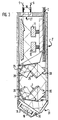
- the device according to FIG. 2 has a treatment laser 1. It is an Nd-YAG laser working in the 1.06 ⁇ m range.
- the light from the treatment laser 1 is passed over a multimode fiber bundle 2, which opens into a distal end section 3 of an endoscopic instrument not shown and described here in detail, for example a flexible endoscope similar to that known from US Pat. No. 5,413,108.
- An electronic evaluation and control unit 4 and two diagnostic lasers 5 and 6 are also arranged outside the endoscopic instrument.
- Each diagnostic laser is connected via a beam splitter block 8 made up of two prisms to a receiving device for remitted light in the form of a photodiode 7.
- the diagnostic lasers 5 and 6 with their associated photodiodes 7 are in turn coupled via a common partially mirrored prism 9 into the same beam path of a single-mode fiber 10, which likewise ends in the distal end section 3.
- the diagnostic lasers 5 and 6 operate in a wavelength range of 1.31 .mu.m and 1.55 .mu.m , which have a different absorption and thus remission in the tissue up to a factor of the order of 10. Similar differences can be achieved in the UV range (0.2 ⁇ m and 0.35 ⁇ m wavelength).
- the laser 5,6 is designed as a laser diode, wherein said operating in the 1.31 ⁇ m-area laser 5 is substantially the topology detecting the functions to be examined tissue region, while operating in the 1.55 ⁇ m-area laser 6 for detecting topology and tissue-specific considerations.
- Laser beams of the diagnostic lasers 5 and 6 are within the end section 3 a suitable vertical mirror scanner 12 and subsequently fed to a horizontal scanner 11.
- the scanners 11, 12 It is silicon two-axis scanner, which is due to electromagnetic Swing excitation around an axis at a specified frequency.
- the Axes of the scanners 11 and 12 are arranged so that the monomode fiber 10 coming light beams in two planes offset by 90 ° to each other to get distracted. Due to this deflection, the punctiform rays of light directed to an essentially square field.
- each a beam splitter block 14 fed to then in a further distal prism block 15 to be reunited.
- Via a prism block behind it 16 is then in this beam path of the diagnostic laser 5, the beam path of the treatment laser 1 coupled.
- This common beam path 17 passes through a lens 18 of an autofocus device before passing over the distal side Window 19 exits the distal end portion 3 of the device.
- the lens 18 is via a magnetic coil arrangement, as is usual with autofocus devices, in Axial direction of the beam path 17 movable.
- the autofocus device works in time windows, in which the diagnosis and therapy function is interrupted, taking advantage of of the light reflected by the diagnostic lasers 5 and 6 on the object. By moving the lens 18 becomes the intensity maximum with the help of the photodiodes 20 of the remitted light and thus the optimally focusing position of the lens 18 determined.
- the one generated by the diagnostic lasers 5, 6 arrives and light remitted by the object through the beam splitter blocks over which Prism block 13 to the scanners 11, 12, which it via the prism 9 back to the Throw beam splitter blocks 8 where there is intensity by means of the photodiodes 7 is detected.
- the signal of the photodiodes 7 is the electrical evaluation and Control unit 4 supplied in which a pixel assignment corresponding to the current scanner position in the diagnostic field and thus the structure of one Pixels existing matrix takes place, depending on the wavelength, for one for the light remitted by the diagnostic laser 5 and the other for the light Diagnostic laser 6 remitted light.
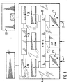
- the signal processing within the control unit 4 is based on that in FIG. 1 illustrated block diagram illustrates.
- the signal of the photodiodes 7 is first fed to an analog-to-digital converter 21.
- the digital The output signal of this analog-digital converter in turn becomes a central one Image processing unit 22 fed.
- this image processing unit 22 the data from the photodiodes 7 digitized data using the synchronization data Scanners 11 and 12 on the one hand, depending on the wavelength, from individual pixels constructed image matrices processed, which, insofar as they from the reflected light of the Diagnostic laser 5 originate, an image memory A and, insofar as they are from the remitted Light from the diagnostic laser 6 originate, are fed to an image memory B.
- the wavelength-dependent in the central image processing unit 22 Computationally linked image data, optionally by subtraction or by forming quotients.
- the arithmetically determined image becomes one Image memory C supplied. While image memories A and B are essentially for the access of the central image processing unit to determine the values for the Serve image memories C and can only be displayed optionally on a monitor 23, the image memory C is at regular intervals, for example three times a Second, queried by an analysis unit 24 while the looped through Signal processed in a video unit 25 and displayed on the monitor 23 becomes.
- the computationally linked image of the image memory is thus displayed on the monitor 23 C, which is topology-adjusted, i.e. only shows an image that especially recognize the contours between malignant and healthy tissue leaves. By switching on pictures A and B, if desired, the topology can also be displayed alone or in addition.
- An electronic evaluation of the image takes place within the analysis unit 24 C, in particular in the central area that is currently being treated by the treatment laser 1 is covered.
- a signal is output to the controller 26 of the treatment laser 1.
- the control unit 4 can be switched so that the controller 26 when pending Signal of the analysis unit 24 automatically switches on the treatment laser 1 or a release of a manual control of the treatment laser 1 which is controlled by the attending doctor. This way it can be reliable be prevented that the treatment laser 1 accidentally to Example is triggered when only healthy tissue has been diagnosed is. Only at a minimum content specified by setting the threshold Malignant tissue in the diagnostic window can trigger the treatment laser take place or this takes place automatically.
- the monitor is always displayed with a repetition frequency of 50 or more Hz, but the query frequency of the image memory is significantly lower can be, for example, three times per second. In this way, the Image processing unit enough time to receive the pixel data coming at different times to compile an overall picture and process it mathematically. in the The display of the monitor is left by the time window for the autofocus not affected, although the treatment laser is locked during this time.
- the embodiment shown in FIG. 3 differs from the one described above characterized in that the beams of the diagnostic lasers 5 and 6 via separate Monomode fibers are guided up to the distal end section 3 ', where they over a suitable prism arrangement 27 are brought together. From there they will again a vertical and then a horizontal scanner 12 or 11 fed. From there, the prism is arranged again a wavelength-dependent beam splitting. In beam splitter blocks 28 Via photodiodes 29, the intensity of that emanating from the diagnostic lasers 5 and 6 Light measured. By recording the radiating diagnostic power In the control unit 4, intensity fluctuations of the diagnostic lasers 5 and 6 can be compensated, thereby excluding another possible source of errors becomes.
- the beams then arrive via further beam splitter blocks 30 a prism arrangement 31 in which the beams of both diagnostic lasers 5 and 6 reunited and with the beam path of the treatment laser 1, which also is connected to the distal end section 3 'via a multimode fiber bundle 2, coupled.
- the common beam path of diagnostic lasers 5, 6 and treatment lasers 1 then leads through the in this embodiment to the longitudinal axis of the distal End portion 3 'inclined lens 18 to the also inclined distal window 19.
- the lens 18 is part of an autofocus device, provided with a coil arrangement on its outer circumference and slidably arranged in the axial direction.
- the one with the coil arrangement interacting permanent ring magnet is with reference numeral 32 in Figure 3 characterized.
- the photodiodes 7 are for detection the intensity of the remitted light in the embodiment according to FIG. 3 arranged within the distal end portion 3 ', at the bottom of the Beam splitter blocks 30. Since here the intensity measurement before passing the Scanner 11 and 12 takes place, the measurement is much easier, because the the intensity of the reflected light is significantly higher and others through the measurement over the whole area a significantly larger amount of light Measurement is available. In this respect, this arrangement is compared to to be preferred based on Figure 2.
- angles ⁇ and ⁇ correspond to those of the embodiment according to FIG. 3.
- the main difference from the previously described embodiment is that three diagnostic lasers, 5, 6 and 33 are provided.
- the wavelengths of these three Diagnostic lasers are selected so that a laser in the red area, a laser in the green area and one works in the blue area so that the rays become natural add white light.
- the prism arrangements are modified accordingly, and there are three photodiodes 29 for detecting power fluctuations in the Diagnostic laser and three photodiodes 7 for wavelength-dependent intensity determination intended.
- the control unit 4 is adapted accordingly, in addition to a further analog-digital converter 21 also a further image memory is provided so that by querying three image memories on the monitor 23rd a natural color image can optionally be displayed for the arithmetically linked image is. This has the particular advantage that the treating doctor is independent from the calculated diagnosis result also a natural picture of the diagnosing tissue site, i.e. the one irradiated by the diagnostic lasers Diagnostic field can make.
Landscapes
- Health & Medical Sciences (AREA)
- Life Sciences & Earth Sciences (AREA)
- Surgery (AREA)
- Biomedical Technology (AREA)
- Engineering & Computer Science (AREA)
- General Health & Medical Sciences (AREA)
- Pathology (AREA)
- Veterinary Medicine (AREA)
- Public Health (AREA)
- Animal Behavior & Ethology (AREA)
- Medical Informatics (AREA)
- Heart & Thoracic Surgery (AREA)
- Biophysics (AREA)
- Molecular Biology (AREA)
- Nuclear Medicine, Radiotherapy & Molecular Imaging (AREA)
- Physics & Mathematics (AREA)
- Radiology & Medical Imaging (AREA)
- Optics & Photonics (AREA)
- Laser Surgery Devices (AREA)
- Radiation-Therapy Devices (AREA)
- Endoscopes (AREA)
Description
- Fig. 1
- ein vereinfachtes Blockschaltbild der erfindungsgemäßen Vorrichtung,
- Fig. 2
- in stark vereinfachter schematischer Darstellung die erfindungsgemäße Vorrichtung mit im Längsschnitt dargestelltem distalen Endabschnitt,
- Fig. 3
- eine andere Ausführung des distalen Endabschnitts im Längsschnitt und
- Fig. 4
- eine weitere Ausführungsvariante in Darstellung nach Figur 3.
Claims (15)
- Vorrichtung zur endoskopischen Diagnose und Behandlung von Gewebe, insbesondere von malignem Gewebe im menschlichen oder tierischen Körper, mit einem Behandlungslaser (1) und mit mindestens einem Diagnoselaser (5, 6), mit einer Empfangseinrichtung (7), mit einer Steuer- und Auswerteinrichtung (4) und mit einem endoskopischen Instrument (3), nahe dessen distalem Ende die Lichtstrahlen aller Laser austreten, dadurch gekennzeichnet, dass mindestens eine Scaneinrichtung (11, 12) vorgesehen ist, welche die Lichtstrahlen des Diagnoselasers (5, 6) über ein Diagnosefeld lenkt, und dass eine Fotodiode (7) als Empfangseinrichtung vorgesehen ist.
- Vorrichtung nach Anspruch 1, dadurch gekennzeichnet, dass mindestens zwei Diagnoselaser (5, 6) unterschiedlicher Wellenlänge vorgesehen sind und dass jedem Diagnoselaser (5, 6) eine Fotodiode (7) zugeordnet ist.
- Vorrichtung nach Anspruch 1 oder 2, dadurch gekennzeichnet, dass die Lichtführung zu den Fotodioden (7) durch Strahlteilerblöcke, Prismen und/oder Spiegel und damit unter Vermeidung des Einsatzes von Lichtwellenleitern erfolgt.
- Vorrichtung nach einem der vorhergehenden Ansprüche, dadurch gekennzeichnet, dass die optischen Achsen von dem Behandlungslaser (1) und von den Diagnoselasern (5, 6) mindestens am distalen Austrittsende der Vorrichtung übereinstimmen.
- Vorrichtung nach einem der vorhergehenden Ansprüche, dadurch gekennzeichnet, dass drei Diagnoselaser (5, 6, 33) unterschiedlicher Wellenlängen vorgesehen sind.
- Vorrichtung nach einem der vorhergehenden Ansprüche, dadurch gekennzeichnet, dass die Diagnoselaser (5, 6, 33) jeweils in den Wellenlängenbereichen rot, grün und blau arbeiten.
- Vorrichtung nach einem der vorhergehenden Ansprüche, dadurch gekennzeichnet, dass die Fotodiode / Fotodioden (7) in einem distalen Endabschnitt (3) des endoskopischen Instrumentes angeordnet sind.
- Vorrichtung nach einem der vorhergehenden Ansprüche, dadurch gekennzeichnet, dass die Scaneinrichtung (11, 12) in dem distalen Endabschnitt (3) des endoskopischen Instrumentes angeordnet ist.
- Vorrichtung nach einem der vorhergehenden Ansprüche, dadurch gekennzeichnet, dass die Strahlengänge der Diagnoselaser (5, 6, 33) vor dem Auftreffen auf eine horizontale und eine vertikale Scaneinrichtung (11, 12) zusammengeführt sind, wobei die Scaneinrichtungen (11, 12) im distalen Endabschnitt (3) des endoskopischen Instrumentes angeordnet sind.
- Vorrichtung nach einem der vorhergehenden Ansprüche, dadurch gekennzeichnet, dass eine Fotodiode (7) selektiv das vom Bestrahlungsort reflektierte Licht im Wesentlichen einer Wellenlänge erfasst, wobei die Wellenlänge der des zugeordneten Diagnoselasers (5, 6, 33) entspricht.
- Vorrichtung nach einem der vorhergehenden Ansprüche, dadurch gekennzeichnet, dass die Fotodioden (7) im distalen Endabschnitt (3) zwischen dem distalen Ende und den Scaneinrichtungen (11, 12) angeordnet sind.
- Vorrichtung nach einem der vorhergehenden Ansprüche, dadurch gekennzeichnet, dass die Fotodiode (7) die Intensität des auftreffenden Lichtes erfasst, und dass in der Steuer- und Auswerteinrichtung (4) anhand des zeitlichen Signalverlaufs an der jeweiligen Fotodiode (7) und der jeweiligen Stellungen der Scaneinrichtungen (11, 12) eine bildgebende Matrix zur jeweiligen Wellenlänge ermittelt, die Matrizes unterschiedlicher Wellenlängen miteinander rechnerisch verknüpft werden und in Abhängigkeit des Ergebnisses die Freigabe und/oder Auslösung des Behandlungslasers (1) gesteuert ist.
- Vorrichtung nach einem der vorhergehenden Ansprüche, dadurch gekennzeichnet, dass im distalen Endabschnitt (3) eine Autofokuseinrichtung (18, 32) angeordnet ist, deren Strahlengang mit dem der Diagnoselaser (5, 6, 33) sowie dem des Behandlungslasers (1) mindestens am distalen Ende des endoskopischen Instrumentes zusammenfällt.
- Vorrichtung nach einem der vorhergehenden Ansprüche, dadurch gekennzeichnet, dass der distale Endabschnitt (3) ein Abschlussfenster (19) aufweist, dem eine Linse (18) der Autofokuseinrichtung (18, 32) vorgelagert ist, die in Richtung ihrer optischen Achse zum Zwecke der Fokussierung verlagerbar ist.
- Vorrichtung nach einem der vorhergehenden Ansprüche, dadurch gekennzeichnet, dass mindestens eine Fotodiode (7) auch Teil der Autofokuseinrichtung (18, 32) bildet.
Applications Claiming Priority (2)
| Application Number | Priority Date | Filing Date | Title |
|---|---|---|---|
| DE19646236A DE19646236C2 (de) | 1996-11-08 | 1996-11-08 | Vorrichtung zur endoskopischen Diagnose und Behandlung von Gewebe |
| DE19646236 | 1996-11-08 |
Publications (3)
| Publication Number | Publication Date |
|---|---|
| EP0845238A2 EP0845238A2 (de) | 1998-06-03 |
| EP0845238A3 EP0845238A3 (de) | 1998-12-16 |
| EP0845238B1 true EP0845238B1 (de) | 2001-08-29 |
Family
ID=7811116
Family Applications (1)
| Application Number | Title | Priority Date | Filing Date |
|---|---|---|---|
| EP97119015A Expired - Lifetime EP0845238B1 (de) | 1996-11-08 | 1997-10-31 | Vorrichtung zur endoskopischen Diagnose und Behandlung von Gewebe |
Country Status (3)
| Country | Link |
|---|---|
| US (1) | US5989181A (de) |
| EP (1) | EP0845238B1 (de) |
| DE (2) | DE19646236C2 (de) |
Families Citing this family (11)
| Publication number | Priority date | Publication date | Assignee | Title |
|---|---|---|---|---|
| DE19816155A1 (de) * | 1998-04-09 | 1999-10-14 | Simon Wagner | Beleuchtungsvorrichtung und -verfahren für endoskopartige Systeme |
| JP5088990B2 (ja) * | 1999-01-26 | 2012-12-05 | Hoya株式会社 | 内視鏡用の自己蛍光画像化システム |
| DE19947812C2 (de) * | 1999-10-05 | 2001-11-22 | Winter & Ibe Olympus | Beleuchtungseinrichtung für Endoskope mit Helligkeitssteuerung |
| DE50210706D1 (de) * | 2001-03-22 | 2007-09-27 | Ese Embedded System Engineerin | Vorrichtung zur simultanen detektion von strahlungen unterschiedlicher wellenlänge |
| DE10115426C2 (de) * | 2001-03-29 | 2003-03-13 | W & H Dentalwerk Buermoos Ges | Vorrichtung und Verfahrens zur Laser-Ablation von organischem und anorganischem Material |
| DE10117347B4 (de) * | 2001-04-06 | 2006-04-13 | W&H Dentalwerk Bürmoos Gesellschaft m.b.H. | Laserbehandlungsgeräte mit Beleuchtungsystem |
| SE522697C2 (sv) * | 2001-11-14 | 2004-03-02 | Spectracure Ab | Terapi- och diagnossystem med fördelare för distribution av strålning |
| WO2015124159A1 (en) | 2014-02-21 | 2015-08-27 | 3Dintegrated Aps | A set comprising a surgical instrument |
| US11020144B2 (en) | 2015-07-21 | 2021-06-01 | 3Dintegrated Aps | Minimally invasive surgery system |
| JP6776327B2 (ja) | 2015-07-21 | 2020-10-28 | スリーディインテグレイテッド アーペーエス3Dintegrated Aps | カニューレアセンブリキット、套管針アセンブリキット、スリーブアセンブリ、低侵襲性手術システム及び方法 |
| DK178899B1 (en) | 2015-10-09 | 2017-05-08 | 3Dintegrated Aps | A depiction system |
Citations (1)
| Publication number | Priority date | Publication date | Assignee | Title |
|---|---|---|---|---|
| US5413108A (en) * | 1993-04-21 | 1995-05-09 | The Research Foundation Of City College Of New York | Method and apparatus for mapping a tissue sample for and distinguishing different regions thereof based on luminescence measurements of cancer-indicative native fluorophor |
Family Cites Families (6)
| Publication number | Priority date | Publication date | Assignee | Title |
|---|---|---|---|---|
| JPS5940869A (ja) * | 1982-08-31 | 1984-03-06 | 工業技術院長 | レ−ザ光パルスを用いた癌の治療装置 |
| DE3331586A1 (de) * | 1983-09-01 | 1985-03-28 | Fa. Carl Zeiss, 7920 Heidenheim | Ophthalmologisches kombinationsgeraet fuer diagnose und therapie |
| DE3740318A1 (de) * | 1986-11-29 | 1988-07-28 | Olympus Optical Co | Abbildungseinrichtung und ein diese einrichtung verwendendes endoskop |
| DE4102614C2 (de) * | 1991-01-30 | 1996-08-29 | Dornier Medizintechnik | Endoskop zum Inspizieren von Körperhöhlen, insbesondere zur Tumor-Detektierung |
| JP3169998B2 (ja) * | 1991-10-04 | 2001-05-28 | オリンパス光学工業株式会社 | 内視鏡装置 |
| JP3631257B2 (ja) * | 1992-08-28 | 2005-03-23 | オリンパス株式会社 | 電子内視鏡装置 |
-
1996
- 1996-11-08 DE DE19646236A patent/DE19646236C2/de not_active Expired - Fee Related
-
1997
- 1997-10-31 EP EP97119015A patent/EP0845238B1/de not_active Expired - Lifetime
- 1997-10-31 DE DE59704432T patent/DE59704432D1/de not_active Expired - Lifetime
- 1997-11-10 US US08/968,047 patent/US5989181A/en not_active Expired - Lifetime
Patent Citations (1)
| Publication number | Priority date | Publication date | Assignee | Title |
|---|---|---|---|---|
| US5413108A (en) * | 1993-04-21 | 1995-05-09 | The Research Foundation Of City College Of New York | Method and apparatus for mapping a tissue sample for and distinguishing different regions thereof based on luminescence measurements of cancer-indicative native fluorophor |
Also Published As
| Publication number | Publication date |
|---|---|
| EP0845238A2 (de) | 1998-06-03 |
| EP0845238A3 (de) | 1998-12-16 |
| DE59704432D1 (de) | 2001-10-04 |
| DE19646236A1 (de) | 1998-05-20 |
| DE19646236C2 (de) | 1998-11-19 |
| US5989181A (en) | 1999-11-23 |
Similar Documents
| Publication | Publication Date | Title |
|---|---|---|
| DE10038875B4 (de) | Endoskopsystem | |
| DE10053447B4 (de) | Endoskopsystem | |
| DE10141559B4 (de) | Videoendoskopsystem und Beleuchtungsoptik | |
| DE10041878B4 (de) | Endoskopsystem | |
| DE69502944T2 (de) | Bildformungsanordnung mittels infrarot-fluorezenz für ein endoskop oder fiberskop | |
| DE60024059T2 (de) | Vorrichtung zur autofluoreszensbildgebung für ein endoskop | |
| DE10031818A1 (de) | Endoskopsystem | |
| DE19653413C2 (de) | Rastermikroskop, bei dem eine Probe in mehreren Probenpunkten gleichzeitig optisch angeregt wird | |
| DE60109989T2 (de) | Vorrichtung zur Aufnahme von Fluoreszenzbildern | |
| DE60205408T2 (de) | Konfokale abbildungsgeräte insbesondere für ein endoskop | |
| DE102008000225B3 (de) | Fundusabtastvorrichtung | |
| EP1262751B1 (de) | Vorrichtung und Verfahren zur Lichtanalyse | |
| DE4200741C2 (de) | Einrichtung zum Erkennen von Karies an Zähnen | |
| DE69904214T2 (de) | Vorrichtung zur Beobachtung des Inneren eines Körpers mit verbesserter Beobachtungsqualität | |
| DE10136419B4 (de) | Optisches System für eine Lichtquellenvorrichtung eines Videoendoskopsystems | |
| DE68912444T2 (de) | Vorrichtung zum Ausrichten eines ophthalmologischen Instruments. | |
| DE102009060621B4 (de) | Abtastendoskopeinrichtung und Abtastendoskop | |
| DE102009059979A1 (de) | Endoskopsystem mit Abstastfunktion | |
| DE10043162A1 (de) | Lichtleitfaserbündel und Endoskopeinrichtung | |
| DE3740318A1 (de) | Abbildungseinrichtung und ein diese einrichtung verwendendes endoskop | |
| DE3432157A1 (de) | Bildaufnahmevorrichtung fuer ein endoskop | |
| EP0845238B1 (de) | Vorrichtung zur endoskopischen Diagnose und Behandlung von Gewebe | |
| DE10139009A1 (de) | Videoendoskopsystem | |
| DE10039182A1 (de) | Endoskopsystem,optisches Abtastsystem und Polygonspiegel | |
| DE60016533T2 (de) | Vorrichtung zur Erfassung eines Fluoreszenzbildes |
Legal Events
| Date | Code | Title | Description |
|---|---|---|---|
| PUAI | Public reference made under article 153(3) epc to a published international application that has entered the european phase |
Free format text: ORIGINAL CODE: 0009012 |
|
| AK | Designated contracting states |
Kind code of ref document: A2 Designated state(s): DE FR GB IT |
|
| PUAL | Search report despatched |
Free format text: ORIGINAL CODE: 0009013 |
|
| AK | Designated contracting states |
Kind code of ref document: A3 Designated state(s): AT BE CH DE DK ES FI FR GB GR IE IT LI LU MC NL PT SE |
|
| 17P | Request for examination filed |
Effective date: 19990201 |
|
| 17Q | First examination report despatched |
Effective date: 19990602 |
|
| AKX | Designation fees paid |
Free format text: DE FR GB IT |
|
| GRAG | Despatch of communication of intention to grant |
Free format text: ORIGINAL CODE: EPIDOS AGRA |
|
| GRAG | Despatch of communication of intention to grant |
Free format text: ORIGINAL CODE: EPIDOS AGRA |
|
| GRAH | Despatch of communication of intention to grant a patent |
Free format text: ORIGINAL CODE: EPIDOS IGRA |
|
| GRAH | Despatch of communication of intention to grant a patent |
Free format text: ORIGINAL CODE: EPIDOS IGRA |
|
| GRAA | (expected) grant |
Free format text: ORIGINAL CODE: 0009210 |
|
| AK | Designated contracting states |
Kind code of ref document: B1 Designated state(s): DE FR GB IT |
|
| RIC1 | Information provided on ipc code assigned before grant |
Free format text: 7A 61B 5/00 A, 7A 61B 18/00 B, 7A 61N 5/06 B, 7A 61B 1/00 B |
|
| REF | Corresponds to: |
Ref document number: 59704432 Country of ref document: DE Date of ref document: 20011004 |
|
| GBT | Gb: translation of ep patent filed (gb section 77(6)(a)/1977) |
Effective date: 20011117 |
|
| REG | Reference to a national code |
Ref country code: GB Ref legal event code: IF02 |
|
| EN | Fr: translation not filed | ||
| PLBE | No opposition filed within time limit |
Free format text: ORIGINAL CODE: 0009261 |
|
| STAA | Information on the status of an ep patent application or granted ep patent |
Free format text: STATUS: NO OPPOSITION FILED WITHIN TIME LIMIT |
|
| 26N | No opposition filed | ||
| ET | Fr: translation filed | ||
| REG | Reference to a national code |
Ref country code: FR Ref legal event code: ERR Free format text: BOPI DE PUBLICATION N: 02/04 PAGES: 244 PARTIE DU BULLETIN CONCERNEE: BREVETS EUROPEENS DONT LA TRADUCTION N'A PAS ETE REMISE A I'INPI IL Y A LIEU DE SUPPRIMER: LA MENTION DE LA NON REMISE. LA REMISE DE LA TRADUCTION EST PUBLIEE DANS LE PRESENT BOPI. |
|
| PGFP | Annual fee paid to national office [announced via postgrant information from national office to epo] |
Ref country code: FR Payment date: 20050928 Year of fee payment: 9 |
|
| PGFP | Annual fee paid to national office [announced via postgrant information from national office to epo] |
Ref country code: GB Payment date: 20051007 Year of fee payment: 9 |
|
| PGFP | Annual fee paid to national office [announced via postgrant information from national office to epo] |
Ref country code: IT Payment date: 20061031 Year of fee payment: 10 |
|
| GBPC | Gb: european patent ceased through non-payment of renewal fee |
Effective date: 20061031 |
|
| REG | Reference to a national code |
Ref country code: FR Ref legal event code: ST Effective date: 20070629 |
|
| PG25 | Lapsed in a contracting state [announced via postgrant information from national office to epo] |
Ref country code: GB Free format text: LAPSE BECAUSE OF NON-PAYMENT OF DUE FEES Effective date: 20061031 |
|
| PG25 | Lapsed in a contracting state [announced via postgrant information from national office to epo] |
Ref country code: FR Free format text: LAPSE BECAUSE OF NON-PAYMENT OF DUE FEES Effective date: 20061031 |
|
| PG25 | Lapsed in a contracting state [announced via postgrant information from national office to epo] |
Ref country code: IT Free format text: LAPSE BECAUSE OF NON-PAYMENT OF DUE FEES Effective date: 20071031 |
|
| PGFP | Annual fee paid to national office [announced via postgrant information from national office to epo] |
Ref country code: DE Payment date: 20131011 Year of fee payment: 17 |
|
| REG | Reference to a national code |
Ref country code: DE Ref legal event code: R119 Ref document number: 59704432 Country of ref document: DE |
|
| PG25 | Lapsed in a contracting state [announced via postgrant information from national office to epo] |
Ref country code: DE Free format text: LAPSE BECAUSE OF NON-PAYMENT OF DUE FEES Effective date: 20150501 |