EP0845199B1 - Haymaking machine - Google Patents
Haymaking machine Download PDFInfo
- Publication number
- EP0845199B1 EP0845199B1 EP97440109A EP97440109A EP0845199B1 EP 0845199 B1 EP0845199 B1 EP 0845199B1 EP 97440109 A EP97440109 A EP 97440109A EP 97440109 A EP97440109 A EP 97440109A EP 0845199 B1 EP0845199 B1 EP 0845199B1
- Authority
- EP
- European Patent Office
- Prior art keywords
- rotor
- rod
- machine according
- axis
- deflector
- Prior art date
- Legal status (The legal status is an assumption and is not a legal conclusion. Google has not performed a legal analysis and makes no representation as to the accuracy of the status listed.)
- Expired - Lifetime
Links
Images


Classifications
-
- A—HUMAN NECESSITIES
- A01—AGRICULTURE; FORESTRY; ANIMAL HUSBANDRY; HUNTING; TRAPPING; FISHING
- A01D—HARVESTING; MOWING
- A01D78/00—Haymakers with tines moving with respect to the machine
- A01D78/08—Haymakers with tines moving with respect to the machine with tine-carrying rotary heads or wheels
- A01D78/10—Haymakers with tines moving with respect to the machine with tine-carrying rotary heads or wheels the tines rotating about a substantially vertical axis
- A01D78/1085—Having two rows of rotors on two different horizontal lines perpendicular to the advance direction of the machine
Definitions
- the present invention relates to a haymaking machine, in particular a swath of mown plants, comprising a frame with several rotors swaths, which swath rotors are rotated during work around substantially vertical axes which are provided with supports fitted with wheels load-bearing, said frame having a traction beam and a connecting beam to which is connected to at least one of the swath rotors, the connecting beam being articulated with respect to the traction beam so that it can be moved with the rotor (s) connected to it laterally to the right and / or to the left, at least the rotor farthest from the articulation with the traction beam being flanked by a swath deflector which is adjustable in several positions with respect to said rotor.
- Document DE 2127 701 B reveals a machine Of this genre.
- the lateral displacements of the beam connection and the rotor (s) connected to it are made by means of jacks hydraulics controlled from the tractor. These lateral displacements are intended to offset the rotors so that they lie on an oblique line by report to the advancement direction for the swath work and align them one behind each other for transportation.
- the object of the present invention is to eliminate the aforementioned drawbacks of the known machine. In particular, it must simplify the operations for adjusting the swath deflector and ensure that they are correctly carried out when each transposition.
- an important characteristic of the invention consists in that the swath deflector is connected by means of at least one lever to a support which is linked to the substantially vertical axis of the rotor next to which said deflector is located swath, that this lever is movable relative to said support and that it is connected to the connecting beam of the frame through a rod.
- This arrangement makes it possible to obtain an automatic adjustment of the position of the swath deflector when moving the connecting beam to put the machine in working position or transport position.
- Said beam drives then the rod that moves the lever so that it brings the deflector closer swathing of the rotor when placing it in transport position and away from it when placing in the working position.
- the means used for the automatic adjustment of the deflector rakes are extremely simple and do not require any maneuvers specific from the user.
- the rod is articulated relative to the lever and to the connecting beam by means of axes of which at least one is movable. This allows to vary the spacing in working position between the deflector and the rotor with which it is associated. The user can thus choose said spacing according to the volume of the forage to be swathed. In addition, whatever the position of this swath deflector during work, it returns automatically place itself against said rotor when positioning transport.
- the machine according to the invention comprises a frame (1) which carries two swath rotors (2 and 3) located at a certain distance from each other. These rotors (2 and 3) are rotatably mounted on substantially vertical axes (4 and 5). Each of these axes (4 and 5) brings to its lower end a support (6) equipped with two carrying wheels (7 and 8).
- This support (6) is hydraulically adjustable in height relative to the axis (4, 5) corresponding so as to be able to modify the distance of the rotor (2 or 3) corresponding to the ground.
- Each of these rotors (2 and 3) essentially consists of a central casing (9) which is mounted on the axis (4, 5) corresponding by means of ball bearings.
- This central casing (9) carries several arms (10) which extend in a plane practically horizontal. Only one of these arms (10) is shown to preserve the clarity of the drawings. They are provided at their ends furthest from said casing (9) raking forks (11).
- Each of these arms (10) is mounted in a bearing the central casing (9) so as to be able to pivot on itself, that is to say around of its longitudinal geometric axis.
- a cam which is fixed on the corresponding axis (4, 5).
- Each fork arm (10) has at its end located inside the central casing (9) a roller which cooperates with said control cam.
- the frame (1) comprises a traction beam (12) and a connecting beam (13).
- the traction beam (12) is fixed on the upper end of the axis substantially vertical (4) of the rotor (2) called the first rotor. It stretches above of this rotor (2), slightly beyond its fork-carrying arms (10).
- a drawbar (14) which allows coupling to a tractor used to move and animate the machine.
- One end of the connecting beam (13) is articulated on the axis (4) substantially vertical of the first rotor (2) so as to be able to pivot around this one. It could as well be articulated on a substantially vertical axis secured to the traction beam (12).
- the other end of the connecting beam (13) is articulated on the substantially vertical axis (5) of the second rotor (3).
- This axis (5) can rotate on itself relative to the beam (13). It has at its end upper a sleeve (15). This is immobilized on said end using a means such as a key or a pin.
- This sleeve (15) has an arm side on which the rod of a hydraulic cylinder (16) is articulated.
- the body of this hydraulic cylinder (16) is articulated on a yoke (17) which is integral with the beam connection (13).
- Said hydraulic cylinder (16) can be controlled from the tractor. It allows the sleeve (15) to be moved so that it rotates the axis (5) substantially vertical on itself.
- a holding device (18) is arranged between the traction beam (12) and the connecting beam (13) in order to favor the placement of the second rotor (3) in a position laterally offset from the first rotor (2) during work.
- This holding device (18) consists of a spring (19) and a jack hydraulic (20). Said spring (19) is hooked, at one of its ends, to a axis (21) integral with the connecting beam (13) and, by its other end, to the rod of the hydraulic cylinder (20). The body of the latter is articulated by means of an axis (22) on the traction beam (12).
- the connecting beam (13) has a hinge pin (23) made in two parts aligned one on the other.
- This axis (23) is substantially horizontal and extends transversely to the beam (13). It is located near the axis (4) substantially vertical of the first rotor (2), which allows the second rotor (3) to move in height significantly around said axis (23), to follow the uneven ground.
- the rotational drive of the two rotors (2 and 3) is provided mechanically from the tractor PTO shaft.
- the traction beam (12) carries at its front end an inlet casing (24) with a shaft (25) to which can be connected a cardan shaft driven from the tractor.
- a first drive shaft which extends from the casing inlet (24) to the first rotor (2). He wears a pinion which meshes with a ring gear secured to the central casing (9) of this rotor (2).
- a second tree of transmission which is housed in the connecting beam (13) extends between the two rotors (2 and 3).
- This second drive shaft has a universal joint at the axis hinge (23) of the connecting beam (13).
- the traction beam (12) carries a protection device (26). It is consisting of a bent tube which surrounds at least the front half of the first rotor (2). A second protection device (27) surrounds the front half of the second rotor (3). It consists of a bent tube fixed on a support transverse (28). This support (28) is connected to the sleeve (15) by a spacer (29).
- the support (28) additionally comprises a plate (30) on which are articulated two levers (31 and 32) by means of axes (33 and 34) substantially vertical. These levers (31 and 32) are substantially parallel and have substantially the same length. They are additionally articulated on a leg (35) by means of pins (36 and 37) substantially vertical.
- This tab (35) is integral with a swath deflector (38) which extends laterally to the second rotor (3).
- This deflector (38) is produced in the form of a grid or canvas and is directed in the direction of advancement (A).
- the lever (31) is connected to the connecting beam (13) of the frame (1) by means of a rod (39). This is articulated, using a first axis (40) substantially vertical, on a leg (41) of the lever (31) and, using a second axis (42) substantially vertical, on a tab (43) which is integral with the connecting beam (13). This tab (43) is located slightly more forward than the axis (5) of the second rotor (3). The tab (41) of the lever (31) is located beyond its axis of articulation (33) on the support (28, 30). Due to this arrangement, the connecting beam (13) moves the rod (39) when it is itself pivoted around the axis (4) substantially vertical of the first rotor (2). Said rod (39) then actuates the lever (31) so that it brings the deflector (38) closer or further away from the second rotor swath (3).
- At least one of the articulation axes (40 and 42) of the rod (39) can be moved in order to adjust the position of the swath deflector (38) at the job.
- the tab (41) of the lever (31) has several holes (44) in each of which can be engaged the axis of articulation (40) of the rod (39). It is thus possible to modify, in choosing one or the other of these orifices (44), the spacing during work between the swath deflector (38) and the rotor (3).
- An intermediate position is shown in phantom in Figure 3.
- the holes (44) lie on an arc of circle (45) whose center is on the articulation axis (42) of the rod (39) when the machine is in the transport position (figure 4). Because of this arrangement, the rod (39) and the lever (31) automatically bring back the deflector (38), from each of the working positions, against the rotor (3) when setting in transport position.
- the rod (39) is articulated by means of the axis (40) on a lug (41) integral with the lever (31) and by means of the axis (42) on a slide (46) which is connected to the connecting beam (13).
- This slide (46) is screwed onto a threaded rod (47) which is held by lugs (48 and 49) integral of the connecting beam (13).
- This threaded rod (47) is free to rotate and locked in translation. It is connected to a crank (50) which allows it to rotate on herself.
- the slide (46) then moves longitudinally on this rod threaded (47). It thus displaces the articulation axis (42) of the rod (39).
- This embodiment therefore actuates the lever (31) so that it pivots around its hinge pin (33) and changes the position of the swath deflector (38) by relative to the rotor (3).
- This embodiment offers a greater choice of positions for the swath deflector (38).
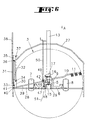
- the threaded rod (47) is advantageously tangent to an arc (51), the center is located on the articulation axis (40) of the rod (39) on the tab (41) of the lever (31) when the machine is in the transport position ( Figure 6). Therefore, the rod (39) and lever (31) automatically bring back the swath deflector (38) against the rotor (3) when placing in the transport position, whatever or its position during work.
- the swather described above can be attached to a tractor using the drawbar (14) and be moved in direction (A).
- the machine When the user arrives at the swath location, the machine is in the transport position in which the rotors (2 and 3) are located one behind the other ( Figure 2).
- To put it in position working (figure 1) it actuates from the tractor the hydraulic cylinder (16) located between the connecting beam (13) and the sleeve (15) so that it lengthens. This one then rotates, via said sleeve (15), the axis (5) substantially vertical of the second rotor (3) on itself.
- the support (6) and the supporting wheels (7 and 8) rotate with said axis (5) and orient themselves towards the left side when look in the direction of travel (A).
- the spacer (29), the support transverse (28) and the protection device (27) also rotate with said axis (5).
- the rod (39) then exerts traction on the tab (41) of the lever (31) of so that it pivots about its hinge pin (33) and moves it away the swath deflector (38) of the rotor (3) automatically.
- the second lever (32) pivots in a similar manner around its axis of articulation (34) so that the deflector (38) is always oriented in the direction of advance (A).
- the desired movement of the deflector (38) can be adjusted according to the volume of the forage to be swathed. So in the if the volume is large, the hinge pin (40) of the rod (39) is placed in the hole (44) of the tab (41) which is closest to the axis of articulation (33) lever (31). This will then pivot outwards as much as possible, in order to obtain a large distance from the rotor (3). On the contrary, if the volume of the the windrow is low, the user will choose an orifice (44) further from the hinge pin (33) of the lever (31). In this case, the pivoting outwards will be weaker, which will favor the formation of a compact swath.
- the spacing between the deflector swath (38) and the rotor (3) is increased when the user moves the slide (46) on the threaded rod (47) in the direction of advance (A).
- the rod (39) then pivots the lever (31) outwards by an angle that can reach 90 °. Lesser spacings are obtained when the slide (46) is located further back on the threaded rod (47). Displacements mentioned above of the slide (46) are made by rotating the threaded rod (47) to using the crank (50).
- the positioning of the axis (40 or 42) of the rod (39) can be carried out before entering the working position or at any time during work.
- the user After rotating the substantially vertical axis (5) as described previously the user moves the machine in direction (A). He can too perform both operations simultaneously.
- the carrying wheels (7 and 8) make then turn the connecting beam (13) around the substantially vertical axis (4) of the first rotor (2) until they are oriented in the direction again progress (A).
- the second rotor (3) In this new position the second rotor (3) is offset relative to the first rotor (2).
- the user actuates the cylinder hydraulic (20) of the holding device (18) so that it shortens. he then tightens the spring (19) which exerts a traction on the connecting beam (13). This therefore remains in the oblique position under all conditions.
- the user actuates the hydraulic means of the supports (6) so lifting the rotors (2 and 3) and clearing the forks (11) from the ground. Then he actuates the hydraulic cylinder (16) so that it shortens and turns the sleeve (15), the substantially vertical axis (5) and the support (6) with the carrying wheels (7 and 8). The latter then pivot to the right and orient in a direction which is parallel to the connecting beam (13).
- the support (28) of the protection device (27) also rotates with the sleeve (15) to the right.
- the rod (39) exercises then a pressure on the tab (41) and makes the lever (31) pivot around its axis hinge (33) so that it automatically returns the swath deflector (38) against the rotor (3).
- the second lever (32) pivots in the same way around of its axis of articulation (34). These two levers (31 and 32) thus position the deflector (38) in a position parallel to the connecting beam (13).
- the deflector (38) is automatically brought back against the rotor (3), in order to obtain a maximum reduction of the width of the machine during transport.
- the control of the hydraulic cylinders (16 and 20) can be synchronized from so as to simplify the work of the user.
Abstract
Description
La présente invention se rapporte à une machine de fenaison, notamment une andaineuse de végétaux fauchés, comportant un bâti avec plusieurs rotors d'andainage, lesquels rotors d'andainage sont entraínés en rotation durant le travail autour d'axes sensiblement verticaux qui sont munis de supports équipés de roues porteuses, ledit bâti possédant une poutre de traction et une poutre de liaison à laquelle est relié au moins un des rotors d'andainage, la poutre de liaison étant articulée par rapport à la poutre de traction de manière à pouvoir être déplacée avec le ou les rotors qui y sont reliés latéralement vers la droite et/ou vers la gauche, au moins le rotor le plus éloigné de l'articulation avec la poutre de traction étant flanquée d'un déflecteur d'andainage qui est réglable dans plusieurs positions par rapport audit rotor. Le document DE 2127 701 B révèle une machine de ce genre.The present invention relates to a haymaking machine, in particular a swath of mown plants, comprising a frame with several rotors swaths, which swath rotors are rotated during work around substantially vertical axes which are provided with supports fitted with wheels load-bearing, said frame having a traction beam and a connecting beam to which is connected to at least one of the swath rotors, the connecting beam being articulated with respect to the traction beam so that it can be moved with the rotor (s) connected to it laterally to the right and / or to the left, at least the rotor farthest from the articulation with the traction beam being flanked by a swath deflector which is adjustable in several positions with respect to said rotor. Document DE 2127 701 B reveals a machine Of this genre.
Sur une machine connue de ce genre, les déplacements latéraux de la poutre de liaison et du ou des rotors qui y sont reliés sont effectués au moyen de vérins hydrauliques commandés depuis le tracteur. Ces déplacements latéraux sont destinés à décaler les rotors de sorte qu'ils se situent sur une ligne oblique par rapport à la direction d'avancement pour le travail d'andainage et à les aligner l'un derrière l'autre pour le transport.On a known machine of this kind, the lateral displacements of the beam connection and the rotor (s) connected to it are made by means of jacks hydraulics controlled from the tractor. These lateral displacements are intended to offset the rotors so that they lie on an oblique line by report to the advancement direction for the swath work and align them one behind each other for transportation.
Lors de ces déplacements, l'utilisateur est toutefois obligé de modifier manuellement la position du déflecteur d'andainage. Il doit l'éloigner du rotor dans la position de travail et le rapprocher au maximum dudit rotor pour le transport afin de réduire la largeur de la machine. Ces opérations sont fastidieuses pour l'utilisateur et entraínent des pertes de temps. Il doit à chaque fois arrêter le tracteur, quitter le siège, se rendre jusqu'à l'extrémité arrière de la machine, déplacer le déflecteur et revenir au tracteur. L'utilisateur peut aussi omettre de modifier la position du déflecteur d'andainage. Cela est particulièrement grave lorsque la machine doit être déplacée sur une route vu que le déflecteur dépasse alors de l'encombrement général de la machine.During these trips, the user is however obliged to modify manually the position of the swath deflector. It must move it away from the rotor in the working position and bring it as close as possible to said rotor for transport to reduce the width of the machine. These operations are tedious for user and result in wasted time. Each time he must stop the tractor, leave the seat, go to the rear end of the machine, move the deflector and return to the tractor. The user can also omit change the position of the swath deflector. This is particularly serious when the machine must be moved on a road since the deflector exceeds then the overall dimensions of the machine.
La présente invention a pour but de supprimer les inconvénients précités de la machine connue. Elle doit notamment simplifier les opérations de réglage du déflecteur d'andainage et assurer qu'elles soient correctement effectuées lors de chaque transposition.The object of the present invention is to eliminate the aforementioned drawbacks of the known machine. In particular, it must simplify the operations for adjusting the swath deflector and ensure that they are correctly carried out when each transposition.
A cet effet, une importante caractéristique de l'invention consiste en ce que le déflecteur d'andainage est relié au moyen d'au moins un levier à un support qui est lié à l'axe sensiblement vertical du rotor à côté duquel se situe ledit déflecteur d'andainage, que ce levier est déplaçable par rapport audit support et qu'il est relié à la poutre de liaison du bâti à travers une tringle.To this end, an important characteristic of the invention consists in that the swath deflector is connected by means of at least one lever to a support which is linked to the substantially vertical axis of the rotor next to which said deflector is located swath, that this lever is movable relative to said support and that it is connected to the connecting beam of the frame through a rod.
Cet agencement permet d'obtenir un réglage automatique de la position du déflecteur d'andainage lors du déplacement de la poutre de liaison pour mettre la machine en position de travail ou en position de transport. Ladite poutre entraíne alors la tringle qui déplace le levier de sorte qu'il rapproche le déflecteur d'andainage du rotor lors de la mise en position de transport et qu'il l'en éloigne lors de la mise en position de travail.This arrangement makes it possible to obtain an automatic adjustment of the position of the swath deflector when moving the connecting beam to put the machine in working position or transport position. Said beam drives then the rod that moves the lever so that it brings the deflector closer swathing of the rotor when placing it in transport position and away from it when placing in the working position.
Les moyens mis en oeuvre pour le réglage automatique du déflecteur d'andainage sont extrêmement simples et ne nécessitent pas de manoeuvres particulières de la part de l'utilisateur.The means used for the automatic adjustment of the deflector rakes are extremely simple and do not require any maneuvers specific from the user.
Selon une autre caractéristique, la tringle est articulée par rapport au levier et à la poutre de liaison au moyen d'axes dont au moins un est déplaçable. Ceci permet de faire varier l'écartement en position de travail entre le déflecteur d'andainage et le rotor auquel il est associé. L'utilisateur peut ainsi choisir ledit écartement en fonction du volume du fourrage à andainer. De plus, quelle que soit la position de ce déflecteur d'andainage durant le travail, il revient automatiquement se placer contre ledit rotor lors de la mise en position de transport.According to another characteristic, the rod is articulated relative to the lever and to the connecting beam by means of axes of which at least one is movable. This allows to vary the spacing in working position between the deflector and the rotor with which it is associated. The user can thus choose said spacing according to the volume of the forage to be swathed. In addition, whatever the position of this swath deflector during work, it returns automatically place itself against said rotor when positioning transport.
D'autres caractéristiques et avantages de l'invention ressortiront de la description qui va suivre et qui se réfère aux dessins annexés qui représentent, à titre d'exemples non limitatifs, quelques formes de réalisation de la machine selon l'invention.Other characteristics and advantages of the invention will emerge from the description which follows and which refers to the appended drawings which represent, at as nonlimiting examples, some embodiments of the machine according to the invention.
Dans ces dessins :
- la figure 1 représente une vue de dessus d'une machine selon l'invention en position de travail ;
- la figure 2 représente la même machine en position de transport ;
- la figure 3 représente une vue de détail d'un exemple de réalisation des moyens de réglage du déflecteur d'andainage dans différentes positions de travail ;
- la figure 4 représente les moyens de réglage selon l'exemple de la figure 3 en position de transport ;
- la figure 5 représente une vue de détail d'un autre exemple de réalisation des moyens de réglage du déflecteur d'andainage dans différentes positions de travail ;
- la figure 6 représente les moyens de réglage selon l'exemple de la figure 5 en position de transport.
- Figure 1 shows a top view of a machine according to the invention in the working position;
- Figure 2 shows the same machine in the transport position;
- FIG. 3 represents a detailed view of an exemplary embodiment of the means for adjusting the swath deflector in different working positions;
- Figure 4 shows the adjustment means according to the example of Figure 3 in the transport position;
- FIG. 5 shows a detailed view of another exemplary embodiment of the means for adjusting the swath deflector in different working positions;
- 6 shows the adjustment means according to the example of Figure 5 in the transport position.
Telle qu'elle est représentée sur les figures 1 et 2, la machine selon l'invention comporte un bâti (1) qui porte deux rotors d'andainage (2 et 3) situés à une certaine distance l'un de l'autre. Ces rotors (2 et 3) sont montés rotatifs sur des axes (4 et 5) sensiblement verticaux. Chacun de ces axes (4 et 5) porte à son extrémité inférieure un support (6) équipé de deux roues porteuses (7 et 8). Ce support (6) est réglable hydrauliquement en hauteur par rapport à l'axe (4, 5) correspondant de manière à pouvoir modifier la distance du rotor (2 ou 3) correspondant par rapport au sol.As shown in Figures 1 and 2, the machine according to the invention comprises a frame (1) which carries two swath rotors (2 and 3) located at a certain distance from each other. These rotors (2 and 3) are rotatably mounted on substantially vertical axes (4 and 5). Each of these axes (4 and 5) brings to its lower end a support (6) equipped with two carrying wheels (7 and 8). This support (6) is hydraulically adjustable in height relative to the axis (4, 5) corresponding so as to be able to modify the distance of the rotor (2 or 3) corresponding to the ground.
Chacun de ces rotors (2 et 3) se compose essentiellement d'un carter central (9) qui est monté sur l'axe (4, 5) correspondant au moyen de roulements à billes. Ce carter central (9) porte plusieurs bras (10) qui s'étendent dans un plan pratiquement horizontal. Un seul de ces bras (10) est représenté pour préserver la clarté des dessins. Ils sont munis à leurs extrémités les plus éloignées dudit carter (9) de fourches de râtelage (11). Chacun de ces bras (10) est monté dans un palier du carter central (9) de manière à pouvoir pivoter sur lui-même, c'est-à-dire autour de son axe géométrique longitudinal. Dans le carter central (9) se situe une came de commande qui est fixée sur l'axe (4, 5) correspondant. Chaque bras porte-fourche (10) possède à son extrémité située à l'intérieur du carter central (9) un galet qui coopère avec ladite came de commande. Each of these rotors (2 and 3) essentially consists of a central casing (9) which is mounted on the axis (4, 5) corresponding by means of ball bearings. This central casing (9) carries several arms (10) which extend in a plane practically horizontal. Only one of these arms (10) is shown to preserve the clarity of the drawings. They are provided at their ends furthest from said casing (9) raking forks (11). Each of these arms (10) is mounted in a bearing the central casing (9) so as to be able to pivot on itself, that is to say around of its longitudinal geometric axis. In the central housing (9) is located a cam which is fixed on the corresponding axis (4, 5). Each fork arm (10) has at its end located inside the central casing (9) a roller which cooperates with said control cam.
Le bâti (1) comprend une poutre de traction (12) et une poutre de liaison (13). La poutre de traction (12) est fixée sur l'extrémité supérieure de l'axe sensiblement vertical (4) du rotor (2) appelé premier rotor. Elle s'étend au-dessus de ce rotor (2), légèrement au-delà de ses bras porte-fourches (10).The frame (1) comprises a traction beam (12) and a connecting beam (13). The traction beam (12) is fixed on the upper end of the axis substantially vertical (4) of the rotor (2) called the first rotor. It stretches above of this rotor (2), slightly beyond its fork-carrying arms (10).
A son extrémité la plus éloignée de l'axe (4) du rotor (2), elle porte un timon (14) qui permet l'attelage à un tracteur servant à déplacer et à animer la machine. L'une des extrémités de la poutre de liaison (13) est articulée sur l'axe (4) sensiblement vertical du premier rotor (2) de manière à pouvoir pivoter autour de celui-ci. Elle pourrait aussi bien être articulée sur un axe sensiblement vertical solidaire de la poutre de traction (12). L'autre extrémité de la poutre de liaison (13) est articulée sur l'axe (5) sensiblement vertical du deuxième rotor (3). Cet axe (5) peut tourner sur lui-même par rapport à la poutre (13). Il comporte à son extrémité supérieure un manchon (15). Celui-ci est immobilisé sur ladite extrémité à l'aide d'un moyen tel qu'une clavette ou une goupille. Ce manchon (15) possède un bras latéral sur lequel est articulée la tige d'un vérin hydraulique (16). Le corps de ce vérin hydraulique (16) est articulé sur une chape (17) qui est solidaire de la poutre de liaison (13). Ledit vérin hydraulique (16) peut être commandé depuis le tracteur. Il permet de déplacer le manchon (15) de telle sorte qu'il fasse tourner l'axe (5) sensiblement vertical sur lui-même.At its end furthest from the axis (4) of the rotor (2), it carries a drawbar (14) which allows coupling to a tractor used to move and animate the machine. One end of the connecting beam (13) is articulated on the axis (4) substantially vertical of the first rotor (2) so as to be able to pivot around this one. It could as well be articulated on a substantially vertical axis secured to the traction beam (12). The other end of the connecting beam (13) is articulated on the substantially vertical axis (5) of the second rotor (3). This axis (5) can rotate on itself relative to the beam (13). It has at its end upper a sleeve (15). This is immobilized on said end using a means such as a key or a pin. This sleeve (15) has an arm side on which the rod of a hydraulic cylinder (16) is articulated. The body of this hydraulic cylinder (16) is articulated on a yoke (17) which is integral with the beam connection (13). Said hydraulic cylinder (16) can be controlled from the tractor. It allows the sleeve (15) to be moved so that it rotates the axis (5) substantially vertical on itself.
Un dispositif de maintien (18) est disposé entre la poutre de traction (12) et la poutre de liaison (13) en vue de favoriser le placement du second rotor (3) dans une position décalée latéralement par rapport au premier rotor (2) durant le travail. Ce dispositif de maintien (18) se compose d'un ressort (19) et d'un vérin hydraulique (20). Ledit ressort (19) est accroché, par l'une de ses extrémités, à un axe (21) solidaire de la poutre de liaison (13) et, par son autre extrémité, à la tige du vérin hydraulique (20). Le corps de ce dernier est articulé au moyen d'un axe (22) sur la poutre de traction (12).A holding device (18) is arranged between the traction beam (12) and the connecting beam (13) in order to favor the placement of the second rotor (3) in a position laterally offset from the first rotor (2) during work. This holding device (18) consists of a spring (19) and a jack hydraulic (20). Said spring (19) is hooked, at one of its ends, to a axis (21) integral with the connecting beam (13) and, by its other end, to the rod of the hydraulic cylinder (20). The body of the latter is articulated by means of an axis (22) on the traction beam (12).
La poutre de liaison (13) comporte un axe d'articulation (23) réalisé en deux parties alignées l'une sur l'autre. Cet axe (23) est sensiblement horizontal et s'étend transversalement à la poutre (13). Il se situe à proximité de l'axe (4) sensiblement vertical du premier rotor (2), ce qui permet au second rotor (3) de se déplacer en hauteur d'une manière importante autour dudit axe (23), pour suivre les dénivellations du sol.The connecting beam (13) has a hinge pin (23) made in two parts aligned one on the other. This axis (23) is substantially horizontal and extends transversely to the beam (13). It is located near the axis (4) substantially vertical of the first rotor (2), which allows the second rotor (3) to move in height significantly around said axis (23), to follow the uneven ground.
L'entraínement en rotation des deux rotors (2 et 3) est assuré mécaniquement à partir de l'arbre de prise de force du tracteur. A cet effet, la poutre de traction (12) porte à son extrémité avant un carter d'entrée (24) avec un arbre (25) auquel peut être relié un arbre à cardans entraíné depuis le tracteur. Dans la poutre de traction (12) est logé un premier arbre de transmission qui s'étend du carter d'entrée (24) jusqu'au premier rotor (2). Il porte un pignon qui engrène avec une couronne dentée solidaire du carter central (9) de ce rotor (2). Un second arbre de transmission qui est logé dans la poutre de liaison (13) s'étend entre les deux rotors (2 et 3). Il comporte à son extrémité avant un pignon qui engrène avec une deuxième couronne dentée qui est également solidaire du carter central (9) du premier rotor (2) et dont la denture est dirigée vers le côté opposé à celle de la couronne précitée. A son extrémité arrière il comporte un autre pignon qui engrène avec une couronne dentée solidaire du carter central (9) du deuxième rotor (3). Ce second arbre de transmission comporte une articulation à cardan au niveau de l'axe d'articulation (23) de la poutre de liaison (13).The rotational drive of the two rotors (2 and 3) is provided mechanically from the tractor PTO shaft. For this purpose, the traction beam (12) carries at its front end an inlet casing (24) with a shaft (25) to which can be connected a cardan shaft driven from the tractor. In the beam of traction (12) is housed a first drive shaft which extends from the casing inlet (24) to the first rotor (2). He wears a pinion which meshes with a ring gear secured to the central casing (9) of this rotor (2). A second tree of transmission which is housed in the connecting beam (13) extends between the two rotors (2 and 3). It has at its front end a pinion which meshes with a second ring gear which is also integral with the central casing (9) of the first rotor (2) and the teeth of which are directed towards the side opposite to that of the aforementioned crown. At its rear end it has another pinion which meshes with a ring gear secured to the central casing (9) of the second rotor (3). This second drive shaft has a universal joint at the axis hinge (23) of the connecting beam (13).
La poutre de traction (12) porte un dispositif de protection (26). Celui-ci est constitué par un tube coudé qui entoure au moins la moitié avant du premier rotor (2). Un deuxième dispositif de protection (27) entoure la moitié avant du deuxième rotor (3). Il est constitué par un tube coudé fixé sur un support transversal (28). Ce support (28) est relié au manchon (15) par une entretoise (29).The traction beam (12) carries a protection device (26). It is consisting of a bent tube which surrounds at least the front half of the first rotor (2). A second protection device (27) surrounds the front half of the second rotor (3). It consists of a bent tube fixed on a support transverse (28). This support (28) is connected to the sleeve (15) by a spacer (29).
Le support (28) comporte en sus une plaque (30) sur laquelle sont articulés deux leviers (31 et 32) au moyen d'axes (33 et 34) sensiblement verticaux. Ces leviers (31 et 32) sont sensiblement parallèles et ont sensiblement la même longueur. Ils sont en sus articulés sur une patte (35) au moyen d'axes (36 et 37) sensiblement verticaux. Cette patte (35) est solidaire d'un déflecteur d'andainage (38) qui s'étend latéralement au deuxième rotor (3). Ce déflecteur (38) est réalisé sous forme de grille ou toile et est dirigé dans la direction d'avancement (A).The support (28) additionally comprises a plate (30) on which are articulated two levers (31 and 32) by means of axes (33 and 34) substantially vertical. These levers (31 and 32) are substantially parallel and have substantially the same length. They are additionally articulated on a leg (35) by means of pins (36 and 37) substantially vertical. This tab (35) is integral with a swath deflector (38) which extends laterally to the second rotor (3). This deflector (38) is produced in the form of a grid or canvas and is directed in the direction of advancement (A).
Le levier (31) est relié à la poutre de liaison (13) du bâti (1) au moyen d'une tringle (39). Celle-ci est articulée, à l'aide d'un premier axe (40) sensiblement vertical, sur une patte (41) du levier (31) et, à l'aide d'un second axe (42) sensiblement vertical, sur une patte (43) qui est solidaire de la poutre de liaison (13). Cette patte (43) se situe légèrement plus en avant que l'axe (5) du deuxième rotor (3). La patte (41) du levier (31) se situe au-delà de son axe d'articulation (33) sur le support (28, 30). En raison de cet agencement, la poutre de liaison (13) déplace la tringle (39) lorsqu'elle est elle même pivotée autour de l'axe (4) sensiblement vertical du premier rotor (2). Ladite tringle (39) actionne alors le levier (31) de sorte qu'il rapproche ou éloigne le déflecteur (38) du second rotor d'andainage (3).The lever (31) is connected to the connecting beam (13) of the frame (1) by means of a rod (39). This is articulated, using a first axis (40) substantially vertical, on a leg (41) of the lever (31) and, using a second axis (42) substantially vertical, on a tab (43) which is integral with the connecting beam (13). This tab (43) is located slightly more forward than the axis (5) of the second rotor (3). The tab (41) of the lever (31) is located beyond its axis of articulation (33) on the support (28, 30). Due to this arrangement, the connecting beam (13) moves the rod (39) when it is itself pivoted around the axis (4) substantially vertical of the first rotor (2). Said rod (39) then actuates the lever (31) so that it brings the deflector (38) closer or further away from the second rotor swath (3).
Au moins un des axes d'articulation (40 et 42) de la tringle (39) peut être déplacé en vue de pouvoir régler la position du déflecteur d'andainage (38) au travail. Dans l'exemple représenté sur les figures 3 et 4, la patte (41) du levier (31) comporte plusieurs orifices (44) dans chacun desquels peut être engagé l'axe d'articulation (40) de la tringle (39). Il est ainsi possible de modifier, en choisissant l'un ou l'autre de ces orifices (44), l'écartement durant le travail entre le déflecteur d'andainage (38) et le rotor (3). Une position intermédiaire est représentée en traits mixtes sur la figure 3. Les orifices (44) se situent sur un arc de cercle (45) dont le centre se trouve sur l'axe d'articulation (42) de la tringle (39) lorsque la machine est en position de transport (figure 4). En raison de cette disposition, la tringle (39) et le levier (31) ramènent automatiquement le déflecteur (38), à partir de chacune des positions de travail, contre le rotor (3) lors de la mise en position de transport.At least one of the articulation axes (40 and 42) of the rod (39) can be moved in order to adjust the position of the swath deflector (38) at the job. In the example shown in Figures 3 and 4, the tab (41) of the lever (31) has several holes (44) in each of which can be engaged the axis of articulation (40) of the rod (39). It is thus possible to modify, in choosing one or the other of these orifices (44), the spacing during work between the swath deflector (38) and the rotor (3). An intermediate position is shown in phantom in Figure 3. The holes (44) lie on an arc of circle (45) whose center is on the articulation axis (42) of the rod (39) when the machine is in the transport position (figure 4). Because of this arrangement, the rod (39) and the lever (31) automatically bring back the deflector (38), from each of the working positions, against the rotor (3) when setting in transport position.
Dans l'exemple selon les figures 5 et 6, la tringle (39) est articulée au moyen de l'axe (40) sur une patte (41) solidaire du levier (31) et au moyen de l'axe (42) sur un coulisseau (46) qui est relié à la poutre de liaison (13). Ce coulisseau (46) est vissé sur une tige filetée (47) qui est tenue par des pattes (48 et 49) solidaires de la poutre de liaison (13). Cette tige filetée (47) est libre en rotation et bloquée en translation. Elle est reliée à une manivelle (50) qui permet de la faire tourner sur elle-même. Le coulisseau (46) se déplace alors longitudinalement sur cette tige filetée (47). Il déplace ainsi l'axe d'articulation (42) de la tringle (39). Cette dernière actionne de ce fait le levier (31) de telle sorte qu'il pivote autour de son axe d'articulation (33) et modifie la position du déflecteur d'andainage (38) par rapport au rotor (3). Ce mode de réalisation offre un plus grand choix de positions pour le déflecteur d'andainage (38).In the example according to FIGS. 5 and 6, the rod (39) is articulated by means of the axis (40) on a lug (41) integral with the lever (31) and by means of the axis (42) on a slide (46) which is connected to the connecting beam (13). This slide (46) is screwed onto a threaded rod (47) which is held by lugs (48 and 49) integral of the connecting beam (13). This threaded rod (47) is free to rotate and locked in translation. It is connected to a crank (50) which allows it to rotate on herself. The slide (46) then moves longitudinally on this rod threaded (47). It thus displaces the articulation axis (42) of the rod (39). This the latter therefore actuates the lever (31) so that it pivots around its hinge pin (33) and changes the position of the swath deflector (38) by relative to the rotor (3). This embodiment offers a greater choice of positions for the swath deflector (38).
La tige filetée (47) est avantageusement tangente à un arc de cercle (51) dont le centre se situe sur l'axe d'articulation (40) de la tringle (39) sur la patte (41) du levier (31) lorsque la machine est en position de transport (figure 6). De ce fait, la tringle (39) et le levier (31) ramènent automatiquement le déflecteur d'andainage (38) contre le rotor (3) lors de la mise en position de transport et ce, quelle que soit sa position durant le travail.The threaded rod (47) is advantageously tangent to an arc (51), the center is located on the articulation axis (40) of the rod (39) on the tab (41) of the lever (31) when the machine is in the transport position (Figure 6). Therefore, the rod (39) and lever (31) automatically bring back the swath deflector (38) against the rotor (3) when placing in the transport position, whatever or its position during work.
L'andaineur décrit ci-dessus peut être accroché à un tracteur au moyen du timon (14) et être déplacé dans la direction (A). Lorsque l'utilisateur arrive sur le lieu d'andainage, la machine est dans la position de transport dans laquelle les rotors (2 et 3) se situent l'un derrière l'autre (figure 2). Pour la mettre en position de travail (figure 1), il actionne à partir du tracteur le vérin hydraulique (16) situé entre la poutre de liaison (13) et le manchon (15) de sorte qu'il s'allonge. Celui-ci fait alors tourner, par l'intermédiaire dudit manchon (15), l'axe (5) sensiblement vertical du deuxième rotor (3) sur lui-même. Le support (6) et les roues porteuses (7 et 8) tournent avec ledit axe (5) et s'orientent vers le côté gauche lorsqu'on regarde dans la direction d'avancement (A). L'entretoise (29), le support transversal (28) et le dispositif de protection (27) tournent également avec ledit axe (5). La tringle (39) exerce alors une traction sur la patte (41) du levier (31) de sorte que celui-ci pivote autour de son axe d'articulation (33) et éloigne automatiquement le déflecteur d'andainage (38) du rotor (3). Le deuxième levier (32) pivote d'une manière similaire autour de son axe d'articulation (34) de sorte que le déflecteur (38) soit toujours orienté dans la direction d'avancement (A).The swather described above can be attached to a tractor using the drawbar (14) and be moved in direction (A). When the user arrives at the swath location, the machine is in the transport position in which the rotors (2 and 3) are located one behind the other (Figure 2). To put it in position working (figure 1), it actuates from the tractor the hydraulic cylinder (16) located between the connecting beam (13) and the sleeve (15) so that it lengthens. This one then rotates, via said sleeve (15), the axis (5) substantially vertical of the second rotor (3) on itself. The support (6) and the supporting wheels (7 and 8) rotate with said axis (5) and orient themselves towards the left side when look in the direction of travel (A). The spacer (29), the support transverse (28) and the protection device (27) also rotate with said axis (5). The rod (39) then exerts traction on the tab (41) of the lever (31) of so that it pivots about its hinge pin (33) and moves it away the swath deflector (38) of the rotor (3) automatically. The second lever (32) pivots in a similar manner around its axis of articulation (34) so that the deflector (38) is always oriented in the direction of advance (A).
Dans l'exemple selon les figures 3 et 4, le déplacement souhaité du déflecteur (38) peut être réglé en fonction du volume du fourrage à andainer. Ainsi, dans le cas où le volume est important, l'axe d'articulation (40) de la tringle (39) est placé dans l'orifice (44) de la patte (41) qui est le plus proche de l'axe d'articulation (33) du levier (31). Celui-ci pivotera alors au maximum vers l'extérieur, afin d'obtenir un grand écartement par rapport au rotor (3). Au contraire, si le volume du fourrage à andainer est faible, l'utilisateur choisira un orifice (44) plus éloigné de l'axe d'articulation (33) du levier (31). Dans ce cas, le pivotement vers l'extérieur sera plus faible, ce qui favorisera la formation d'un andain compact.In the example according to Figures 3 and 4, the desired movement of the deflector (38) can be adjusted according to the volume of the forage to be swathed. So in the if the volume is large, the hinge pin (40) of the rod (39) is placed in the hole (44) of the tab (41) which is closest to the axis of articulation (33) lever (31). This will then pivot outwards as much as possible, in order to obtain a large distance from the rotor (3). On the contrary, if the volume of the the windrow is low, the user will choose an orifice (44) further from the hinge pin (33) of the lever (31). In this case, the pivoting outwards will be weaker, which will favor the formation of a compact swath.
Dans l'exemple selon les figures 5 et 6, l'écartement entre le déflecteur d'andainage (38) et le rotor (3) est augmenté lorsque l'utilisateur déplace le coulisseau (46) sur la tige filetée (47) dans la direction d'avancement (A). La tringle (39) fait alors pivoter le levier (31) vers l'extérieur d'un angle pouvant atteindre 90°. Des écartements moins importants sont obtenus lorsque le coulisseau (46) se situe plus en arrière sur la tige filetée (47). Les déplacements précités du coulisseau (46) sont effectués en faisant tourner la tige filetée (47) à l'aide de la manivelle (50).In the example according to FIGS. 5 and 6, the spacing between the deflector swath (38) and the rotor (3) is increased when the user moves the slide (46) on the threaded rod (47) in the direction of advance (A). The rod (39) then pivots the lever (31) outwards by an angle that can reach 90 °. Lesser spacings are obtained when the slide (46) is located further back on the threaded rod (47). Displacements mentioned above of the slide (46) are made by rotating the threaded rod (47) to using the crank (50).
Le positionnement de l'axe (40 ou 42) de la tringle (39) peut être effectué avant la mise en position de travail ou à n'importe quel moment durant le travail.The positioning of the axis (40 or 42) of the rod (39) can be carried out before entering the working position or at any time during work.
Après avoir fait tourner l'axe (5) sensiblement vertical tel que décrit précédemment l'utilisateur déplace la machine dans la direction (A). Il peut aussi effectuer les deux opérations simultanément. Les roues porteuses (7 et 8) font alors tourner la poutre de liaison (13) autour de l'axe (4) sensiblement vertical du premier rotor (2) jusqu'à ce qu'elles soient à nouveau orientées dans la direction d'avancement (A). Dans cette nouvelle position le deuxième rotor (3) est décalé par rapport au premier rotor (2). Dans cette position, l'utilisateur actionne le vérin hydraulique (20) du dispositif de maintien (18) de sorte qu'il se raccourcisse. Il tend alors le ressort (19) qui exerce une traction sur la poutre de liaison (13). Celle-ci reste ainsi dans la position oblique dans toutes les conditions.After rotating the substantially vertical axis (5) as described previously the user moves the machine in direction (A). He can too perform both operations simultaneously. The carrying wheels (7 and 8) make then turn the connecting beam (13) around the substantially vertical axis (4) of the first rotor (2) until they are oriented in the direction again progress (A). In this new position the second rotor (3) is offset relative to the first rotor (2). In this position, the user actuates the cylinder hydraulic (20) of the holding device (18) so that it shortens. he then tightens the spring (19) which exerts a traction on the connecting beam (13). This therefore remains in the oblique position under all conditions.
Il reste à l'utilisateur d'abaisser les rotors (2 et 3) en faisant pivoter les supports (6) vers le bas de sorte que les fourches (11) touchent le sol et à les entraíner en rotation au moyen de l'arbre de prise de force du tracteur. Ils tournent alors dans le même sens (F). Les fourches (11) ramassent, dans la partie avant de leur trajectoire, le fourrage qui se trouve sur le sol. Ensuite, elles le déposent sous la forme d'un andain dans la partie latérale de leur trajectoire. En raison de la disposition des deux rotors (2 et 3), le fourrage déposé par le premier rotor (2) est repris par le deuxième rotor (3) qui forme un andain latéral de plus gros volume contre le déflecteur d'andainage (38).It remains for the user to lower the rotors (2 and 3) by rotating the supports (6) down so that the forks (11) touch the ground and drive in rotation by means of the tractor PTO shaft. They turn then in the same direction (F). The forks (11) pick up, in the front part of their trajectory, the forage that is on the ground. Then they file it under the shape of a swath in the lateral part of their trajectory. Due to arrangement of the two rotors (2 and 3), the forage deposited by the first rotor (2) is taken up by the second rotor (3) which forms a lateral swath of larger volume against the swath deflector (38).
Pour transposer la machine dans la position de transport représentée sur la figure 2, l'utilisateur actionne les moyens hydrauliques des supports (6) de manière à soulever les rotors (2 et 3) et à dégager les fourches (11) du sol. Ensuite, il actionne le vérin hydraulique (16) afin qu'il se raccourcisse et tourne le manchon (15), l'axe (5) sensiblement vertical et le support (6) avec les roues porteuses (7 et 8). Ces dernières pivotent alors vers la droite et s'orientent dans une direction qui est parallèle à la poutre de liaison (13). Le support (28) du dispositif de protection (27) tourne également avec le manchon (15) vers la droite. La tringle (39) exerce alors une pression sur la patte (41) et fait pivoter le levier (31) autour de son axe d'articulation (33) de sorte qu'il ramène automatiquement le déflecteur d'andainage (38) contre le rotor (3). Le deuxième levier (32) pivote de la même manière autour de son axe d'articulation (34). Ces deux leviers (31 et 32) positionnent ainsi le déflecteur (38) dans une position parallèle à la poutre de liaison (13).To transfer the machine to the transport position shown on the Figure 2, the user actuates the hydraulic means of the supports (6) so lifting the rotors (2 and 3) and clearing the forks (11) from the ground. Then he actuates the hydraulic cylinder (16) so that it shortens and turns the sleeve (15), the substantially vertical axis (5) and the support (6) with the carrying wheels (7 and 8). The latter then pivot to the right and orient in a direction which is parallel to the connecting beam (13). The support (28) of the protection device (27) also rotates with the sleeve (15) to the right. The rod (39) exercises then a pressure on the tab (41) and makes the lever (31) pivot around its axis hinge (33) so that it automatically returns the swath deflector (38) against the rotor (3). The second lever (32) pivots in the same way around of its axis of articulation (34). These two levers (31 and 32) thus position the deflector (38) in a position parallel to the connecting beam (13).
Dans chacun des exemples de réalisation selon les figures 3, 4 et 5, 6 le déflecteur (38) est ramené automatiquement contre le rotor (3), afin d'obtenir une réduction maximale de la largeur de la machine au transport.In each of the exemplary embodiments according to FIGS. 3, 4 and 5, 6 the deflector (38) is automatically brought back against the rotor (3), in order to obtain a maximum reduction of the width of the machine during transport.
Il reste alors à actionner le vérin (20) du dispositif de maintien (18) afin qu'il s'allonge et libère le ressort (19) et à déplacer la machine dans la direction (A). Le second rotor (3) et la poutre de liaison (13) pivotent automatiquement autour de l'axe (4) sensiblement vertical du premier rotor (2) et se placent derrière celui-ci. La largeur de la machine est ainsi considérablement réduite.It then remains to actuate the jack (20) of the holding device (18) so that it lengthens and releases the spring (19) and moves the machine in direction (A). The second rotor (3) and the connecting beam (13) automatically rotate around the substantially vertical axis (4) of the first rotor (2) and are placed behind it. The width of the machine is thus considerably reduced.
La commande des vérins hydrauliques (16 et 20) peut être synchronisée de manière à simplifier le travail de l'utilisateur.The control of the hydraulic cylinders (16 and 20) can be synchronized from so as to simplify the work of the user.
Il est bien évident que l'invention n'est pas limitée aux modes de réalisation décrits et représentés sur les dessins annexés. Des modifications sont possibles, notamment en ce qui concerne la constitution des divers éléments ou par substitution d'équivalents techniques, sans pour autant sortir du domaine de protection tel qu'il est défini dans les revendications.It is obvious that the invention is not limited to the embodiments described and shown in the accompanying drawings. Modifications are possible, particularly with regard to the constitution of the various elements or by substitution of technical equivalents, without departing from the scope of protection as defined in the claims.
Claims (12)
- Hay-making machine, especially a windrower of mown plant matter, comprising a frame (1) with several windrowing rotors (2 and 3), which windrowing rotors (2 and 3) are rotated during work about substantially vertical axes (4 and 5) which are equipped with supports (6) fitted with carrier-wheels (7 and 8), the said frame (1) comprising a draft beam (12) and a connecting beam (13) to which at least one of the windrowing rotors (2, 3) is connected, the connecting beam (13) being articulated with respect to the draft beam (12) so that it can be moved, together with the rotor or rotors (2, 3) connected thereto, laterally to the right and/or to the left, at least the rotor (3) furthest from the articulation to the draft beam (12) being flanked by a windrowing deflector (38) which can be adjusted into several positions with respect to the said rotor (3), characterized in that the windrowing deflector (38) is connected by means of at least one lever (31, 32) to a support (28, 30) which is connected to the substantially vertical axis (5) of the rotor (3) beside which the said windrowing deflector (38) is situated, in that the lever (31, 32) can be moved with respect to the support (28, 30) and in that it is connected to the connecting beam (13) via a rod (39).
- Machine according to Claim 1, characterized in that it comprises two levers (31 and 32) which are substantially parallel and have substantially the same length, and which are articulated with respect to the support (28) and to the windrowing deflector (38) by means of substantially vertical axes (33, 34 and 36, 37).
- Machine according to Claim 1 or 2, characterized in that the rod (39) is articulated to a lug (41) of the lever (31) and a lug (43) which is rigidly fastened to the connecting beam (13) by means of substantially vertical axes (40 and 42).
- Machine according to Claim 3, characterized in that the lug (41) is situated beyond the axis (33) articulating the lever (31) to the support (28, 30).
- Machine according to Claim 3, characterized in that at least one of the axes of articulation (40 and 42) of the rod (39) is movable.
- Machine according to Claim 5, characterized in that the lug (41) has several holes (44) for the axis of articulation (40) of the rod (39).
- Machine according to Claim 6, characterized in that the holes (44) in the lug (41) are in an arc of a circle (45) the centre of which is on the other axis of articulation (42) of the rod (39) when the machine is in the transport position.
- Machine according to Claim 1, characterized in that the rod (39) is articulated to a lug (41) which is rigidly fastened to the lever (31) and to a slide (46) connected to the connecting beam (13).
- Machine according to Claim 8, characterized in that the slide (46) is movable along a threaded rod (47) which is held by lugs (48 and 49) which are rigidly fastened to the connecting beam (13).
- Machine according to Claim 9, characterized in that the threaded rod (47) is free to rotate but cannot move in translation.
- Machine according to Claim 10, characterized in that the threaded rod (47) is connected to a cranking handle (50).
- Machine according to Claim 9, characterized in that the threaded rod (47) is tangential to an arc of a circle (51) the centre of which is on the other axis of articulation (40) of the rod (39) when the machine is in the transport position.
Applications Claiming Priority (2)
| Application Number | Priority Date | Filing Date | Title |
|---|---|---|---|
| FR9614819 | 1996-11-26 | ||
| FR9614819A FR2756137B1 (en) | 1996-11-26 | 1996-11-26 | HAYMAKING MACHINE, ESPECIALLY A SWATHER WITH A SWATHING DEFLECTOR AUTOMATICALLY ADJUSTABLE IN DIFFERENT POSITIONS |
Publications (2)
| Publication Number | Publication Date |
|---|---|
| EP0845199A1 EP0845199A1 (en) | 1998-06-03 |
| EP0845199B1 true EP0845199B1 (en) | 2001-05-30 |
Family
ID=9498283
Family Applications (1)
| Application Number | Title | Priority Date | Filing Date |
|---|---|---|---|
| EP97440109A Expired - Lifetime EP0845199B1 (en) | 1996-11-26 | 1997-11-18 | Haymaking machine |
Country Status (7)
| Country | Link |
|---|---|
| US (1) | US6050076A (en) |
| EP (1) | EP0845199B1 (en) |
| AT (1) | ATE201556T1 (en) |
| DE (1) | DE69705013T2 (en) |
| DK (1) | DK0845199T3 (en) |
| ES (1) | ES2157056T3 (en) |
| FR (1) | FR2756137B1 (en) |
Cited By (1)
| Publication number | Priority date | Publication date | Assignee | Title |
|---|---|---|---|---|
| DE202016007555U1 (en) | 2016-12-12 | 2018-03-22 | Pöttinger Landtechnik Gmbh | Agricultural working machine |
Families Citing this family (9)
| Publication number | Priority date | Publication date | Assignee | Title |
|---|---|---|---|---|
| DE29806999U1 (en) * | 1998-04-17 | 1998-07-23 | Multinorm Bv | Haymaking machine |
| FR2790358B1 (en) * | 1999-03-05 | 2001-05-11 | Kuhn Sa | FENAISON MACHINE HAVING AT LEAST ONE SWATHING ROTOR PROVIDED WITH AN ADJUSTABLE DEFLECTOR |
| FR2790637B1 (en) * | 1999-03-12 | 2001-04-27 | Mecanique Et Tolerie M E C A T | TWO-ROTORED RAKE SWATHER |
| DE10017967A1 (en) * | 2000-04-12 | 2001-10-18 | Claas Saulgau Gmbh | Haymaking machine |
| DE202004008500U1 (en) * | 2004-05-28 | 2005-10-06 | Kverneland Gottmadingen Gmbh & Co. Kg | Trailed rotary rake |
| FR2875377B1 (en) * | 2004-09-23 | 2007-01-19 | Kuhn Sa Sa | ANDAINEUSE OF PLANTS WITH THREE ROLLING WHEELS |
| FR3000870A1 (en) * | 2013-01-17 | 2014-07-18 | Kuhn | HUNTING MACHINE HAVING AN IMPROVED DEFLECTOR |
| FR3019440B1 (en) * | 2014-04-08 | 2016-03-25 | Kuhn Sa | FORAGE HARVESTING MACHINE HAVING AN IMPROVED DEFLECTOR |
| GB201610834D0 (en) * | 2016-06-21 | 2016-08-03 | Agco Feucht Gmbh | Agricultural tool control system |
Family Cites Families (32)
| Publication number | Priority date | Publication date | Assignee | Title |
|---|---|---|---|---|
| FR1327063A (en) * | 1962-03-05 | 1963-05-17 | Beet harvester with adjustable storage device | |
| NL6513220A (en) * | 1965-10-13 | 1967-04-14 | ||
| NL6511984A (en) * | 1965-09-15 | 1967-03-16 | Lely Nv C Van Der | |
| DE1582297A1 (en) * | 1965-09-15 | 1970-08-06 | Lely Nv C Van Der | Haymaking machine |
| DE1507324C3 (en) * | 1966-06-24 | 1978-05-11 | Maschinenfabrik Fahr Ag, 7702 Gottmadingen | Rotary tedders |
| NL6713676A (en) * | 1967-10-09 | 1969-04-11 | ||
| CH499254A (en) * | 1968-08-27 | 1970-11-30 | Bucher Guyer Ag Masch | Haymaking machine |
| CH508332A (en) * | 1969-04-16 | 1971-06-15 | Kuhn Freres & Cie | Haymaking machine |
| CA951910A (en) * | 1971-06-02 | 1974-07-30 | John K. Hale | Cooperating windrowing structure for a rotor type raking device |
| DE2127701B1 (en) * | 1971-06-04 | 1972-10-19 | Wilhelm Stoll, Maschinenfabrik Gmbh, 3325 Broistedt | Haymaking machine |
| NL7305169A (en) * | 1973-04-13 | 1974-10-15 | ||
| CH579342A5 (en) * | 1973-10-12 | 1976-09-15 | Lely Nv C Van Der | |
| CA1039515A (en) * | 1973-10-12 | 1978-10-03 | C. Van Der Lely N.V. | Raking machines |
| FR2339330A1 (en) * | 1976-01-30 | 1977-08-26 | Kuhn Sa | Haymaking machine for tedding and swathing |
| FR2342639A1 (en) * | 1976-03-05 | 1977-09-30 | Kuhn Sa | DEVICE ALLOWING THE MODIFICATION OF THE TAPPING ANGLE OF THE TOUPIES OF AN AGRICULTURAL MACHINE OF THE TEDDLE-RAKE TYPE |
| NL7607093A (en) * | 1976-06-29 | 1978-01-02 | Texas Industries Inc | MACHINE FOR CROP PROCESSING. |
| ES237110Y (en) * | 1978-07-05 | 1979-01-16 | APERO DE LABRANZA. | |
| FR2549342B1 (en) * | 1983-07-19 | 1987-10-02 | Kuhn Sa | IMPROVED HAYMAKING MACHINE |
| FR2576744B1 (en) * | 1985-02-06 | 1988-06-17 | Kuhn Sa | IMPROVEMENT ON FLEXIBLE SKIRTS FOR MOVING PRODUCTS ON THE GROUND AND AGRICULTURAL MACHINES EQUIPPED WITH SUCH SKIRTS |
| FR2582186B1 (en) * | 1985-05-21 | 1989-05-05 | Kuhn Sa | IMPROVEMENT IN FENAISON MACHINES WITH MULTIPLE RAKING WHEELS |
| FR2613177B1 (en) * | 1987-04-01 | 1991-06-28 | Kuhn Sa | FENAISON MACHINE |
| FR2632810B2 (en) * | 1987-11-17 | 1991-08-30 | Kuhn Sa | FENAISON MACHINE WITH AT LEAST ONE RAKING WHEEL EQUIPPED WITH CONTROLLED TOOL HOLDER ARMS |
| FR2631775B1 (en) * | 1988-05-26 | 1991-10-11 | Kuhn Sa | AGRICULTURAL MACHINE HAVING AT LEAST ONE ROTOR DRIVED DURING WORK |
| FR2632155B1 (en) * | 1988-06-03 | 1991-10-11 | Kuhn Sa | FENAISON MACHINE HAVING A ROTOR FOR RAKING |
| FR2644320B1 (en) * | 1989-03-20 | 1992-05-07 | Kuhn Sa | AGRICULTURAL MACHINE WITH AT LEAST ONE ROTOR FOR MOVING PRODUCTS ON THE GROUND |
| FR2648310B1 (en) * | 1989-06-16 | 1991-09-20 | Kuhn Sa | AGRICULTURAL MACHINE FOR RAKING, COMPRISING FOLDABLE TOOL HOLDER ARMS |
| DE4021812C2 (en) * | 1989-07-10 | 2000-08-10 | Stoll Maschf Gmbh Wilhelm | Haymaking machine |
| FR2661312B1 (en) * | 1990-04-27 | 1992-07-17 | Kuhn Sa | FENAISON MACHINE WITH SEVERAL ROTORS. |
| FR2678804B1 (en) * | 1991-07-11 | 1998-09-18 | Kuhn Sa | HATCHING MACHINE COMPRISING AT LEAST ONE RAKING WHEEL, A PROTECTION DEVICE AND AN ADJUSTABLE DEFLECTOR. |
| FR2700916B1 (en) * | 1993-01-29 | 1999-02-26 | Kuhn Sa | FENAISON MACHINE WITH AN ADJUSTABLE SIDE DEFLECTOR. |
| FR2719443B1 (en) * | 1994-05-04 | 1996-07-05 | Kuhn Sa | Haymaking machine, in particular a hay rake. |
| FR2722365B1 (en) * | 1994-07-13 | 1996-09-20 | Kuhn Sa Societe Anonyme | FENAISON MACHINE, PARTICULARLY A PLANT SWATHER WITH CONTROLLED FORK ARM |
-
1996
- 1996-11-26 FR FR9614819A patent/FR2756137B1/en not_active Expired - Fee Related
-
1997
- 1997-11-18 DE DE69705013T patent/DE69705013T2/en not_active Expired - Lifetime
- 1997-11-18 EP EP97440109A patent/EP0845199B1/en not_active Expired - Lifetime
- 1997-11-18 AT AT97440109T patent/ATE201556T1/en active
- 1997-11-18 DK DK97440109T patent/DK0845199T3/en active
- 1997-11-18 ES ES97440109T patent/ES2157056T3/en not_active Expired - Lifetime
- 1997-11-24 US US08/977,683 patent/US6050076A/en not_active Expired - Lifetime
Cited By (2)
| Publication number | Priority date | Publication date | Assignee | Title |
|---|---|---|---|---|
| DE202016007555U1 (en) | 2016-12-12 | 2018-03-22 | Pöttinger Landtechnik Gmbh | Agricultural working machine |
| EP3332628A1 (en) | 2016-12-12 | 2018-06-13 | PÖTTINGER Landtechnik GmbH | Agricultural machine |
Also Published As
| Publication number | Publication date |
|---|---|
| ES2157056T3 (en) | 2001-08-01 |
| EP0845199A1 (en) | 1998-06-03 |
| DE69705013T2 (en) | 2002-01-03 |
| FR2756137B1 (en) | 1999-01-22 |
| ATE201556T1 (en) | 2001-06-15 |
| FR2756137A1 (en) | 1998-05-29 |
| DK0845199T3 (en) | 2001-09-17 |
| US6050076A (en) | 2000-04-18 |
| DE69705013D1 (en) | 2001-07-05 |
Similar Documents
| Publication | Publication Date | Title |
|---|---|---|
| EP0429381B1 (en) | Farm machine having a deformable suspension mechanism | |
| EP0845199B1 (en) | Haymaking machine | |
| EP0763321B1 (en) | Haymaking machine | |
| EP1290936B1 (en) | Haymaking machine | |
| EP1076482B1 (en) | Hay harvesting machine provided with at least a swathing rotor equipped with a deflector with adjustable position | |
| EP0514302B1 (en) | Improved crop windrower | |
| EP0692185B1 (en) | Haymaking machine, especially a swather with controlled fork-carrying arms | |
| EP0772969A1 (en) | Haymaking machine with at least one windrowing rotor | |
| FR2664127A1 (en) | AGRICULTURAL MACHINE, ESPECIALLY AN ANDAINEUSE OF PLANTS, WITH ADJUSTABLE WORKING WIDTH. | |
| EP0797913B1 (en) | Haymaking machine | |
| EP0779022B1 (en) | Haymaking machine | |
| FR2759245A1 (en) | FENAISON MACHINE WITH A GROUND SUPPORT DEVICE INCLUDING AT LEAST A BALANCER WITH TWO CARRIER WHEELS AND A MEANS FOR MOVING THIS BALANCER FOR TRANSPORT | |
| EP0426588A1 (en) | Improvement for agricultural machines especially for haymaking machines | |
| FR2707450A1 (en) | Hay-making machine with tedding or windrowing rotors equipped with wheels for resting on the ground | |
| EP0654209B1 (en) | Haymaking machine | |
| EP0733302B1 (en) | Haymaking machine | |
| EP0532443B1 (en) | Haymaking machine with adjustable wheels | |
| EP0914766B1 (en) | Haymaking machine | |
| FR3135187A1 (en) | Secure haymaking machine and related protocol | |
| EP0811314B1 (en) | Agricultural machine | |
| FR2798817A1 (en) | Swathing machine, for hay making, consists of primary and secondary beams with rotors, with rotors supported by wheels mounted on transverse beams carried by support axis mounted beneath swathing rotors | |
| FR2549686A1 (en) | Tedder with carrying devices and folding drive shafts | |
| EP0998843A1 (en) | Haymaking machine |
Legal Events
| Date | Code | Title | Description |
|---|---|---|---|
| PUAI | Public reference made under article 153(3) epc to a published international application that has entered the european phase |
Free format text: ORIGINAL CODE: 0009012 |
|
| AK | Designated contracting states |
Kind code of ref document: A1 Designated state(s): AT DE DK ES FR GB IT NL |
|
| AX | Request for extension of the european patent |
Free format text: AL;LT;LV;MK;RO;SI |
|
| 17P | Request for examination filed |
Effective date: 19981116 |
|
| AKX | Designation fees paid |
Free format text: AT DE DK ES FR GB IT NL |
|
| RBV | Designated contracting states (corrected) |
Designated state(s): AT DE DK ES FR GB IT NL |
|
| GRAG | Despatch of communication of intention to grant |
Free format text: ORIGINAL CODE: EPIDOS AGRA |
|
| GRAG | Despatch of communication of intention to grant |
Free format text: ORIGINAL CODE: EPIDOS AGRA |
|
| GRAH | Despatch of communication of intention to grant a patent |
Free format text: ORIGINAL CODE: EPIDOS IGRA |
|
| 17Q | First examination report despatched |
Effective date: 20000927 |
|
| GRAH | Despatch of communication of intention to grant a patent |
Free format text: ORIGINAL CODE: EPIDOS IGRA |
|
| GRAA | (expected) grant |
Free format text: ORIGINAL CODE: 0009210 |
|
| AK | Designated contracting states |
Kind code of ref document: B1 Designated state(s): AT DE DK ES FR GB IT NL |
|
| REF | Corresponds to: |
Ref document number: 201556 Country of ref document: AT Date of ref document: 20010615 Kind code of ref document: T |
|
| ITF | It: translation for a ep patent filed |
Owner name: BARZANO' E ZANARDO MILANO S.P.A. |
|
| REF | Corresponds to: |
Ref document number: 69705013 Country of ref document: DE Date of ref document: 20010705 |
|
| REG | Reference to a national code |
Ref country code: ES Ref legal event code: FG2A Ref document number: 2157056 Country of ref document: ES Kind code of ref document: T3 |
|
| GBT | Gb: translation of ep patent filed (gb section 77(6)(a)/1977) |
Effective date: 20010810 |
|
| REG | Reference to a national code |
Ref country code: DK Ref legal event code: T3 |
|
| REG | Reference to a national code |
Ref country code: GB Ref legal event code: IF02 |
|
| PLBE | No opposition filed within time limit |
Free format text: ORIGINAL CODE: 0009261 |
|
| STAA | Information on the status of an ep patent application or granted ep patent |
Free format text: STATUS: NO OPPOSITION FILED WITHIN TIME LIMIT |
|
| 26N | No opposition filed | ||
| REG | Reference to a national code |
Ref country code: FR Ref legal event code: PLFP Year of fee payment: 19 |
|
| PGFP | Annual fee paid to national office [announced via postgrant information from national office to epo] |
Ref country code: DK Payment date: 20151022 Year of fee payment: 19 |
|
| PGFP | Annual fee paid to national office [announced via postgrant information from national office to epo] |
Ref country code: DE Payment date: 20151022 Year of fee payment: 19 Ref country code: GB Payment date: 20151027 Year of fee payment: 19 Ref country code: IT Payment date: 20151023 Year of fee payment: 19 |
|
| PGFP | Annual fee paid to national office [announced via postgrant information from national office to epo] |
Ref country code: AT Payment date: 20151022 Year of fee payment: 19 Ref country code: ES Payment date: 20151110 Year of fee payment: 19 Ref country code: NL Payment date: 20151021 Year of fee payment: 19 Ref country code: FR Payment date: 20151023 Year of fee payment: 19 |
|
| REG | Reference to a national code |
Ref country code: DE Ref legal event code: R119 Ref document number: 69705013 Country of ref document: DE |
|
| REG | Reference to a national code |
Ref country code: DK Ref legal event code: EBP Effective date: 20161130 |
|
| REG | Reference to a national code |
Ref country code: NL Ref legal event code: MM Effective date: 20161201 |
|
| REG | Reference to a national code |
Ref country code: AT Ref legal event code: MM01 Ref document number: 201556 Country of ref document: AT Kind code of ref document: T Effective date: 20161118 |
|
| GBPC | Gb: european patent ceased through non-payment of renewal fee |
Effective date: 20161118 |
|
| REG | Reference to a national code |
Ref country code: FR Ref legal event code: ST Effective date: 20170731 |
|
| PG25 | Lapsed in a contracting state [announced via postgrant information from national office to epo] |
Ref country code: AT Free format text: LAPSE BECAUSE OF NON-PAYMENT OF DUE FEES Effective date: 20161118 |
|
| PG25 | Lapsed in a contracting state [announced via postgrant information from national office to epo] |
Ref country code: NL Free format text: LAPSE BECAUSE OF NON-PAYMENT OF DUE FEES Effective date: 20161201 |
|
| PG25 | Lapsed in a contracting state [announced via postgrant information from national office to epo] |
Ref country code: FR Free format text: LAPSE BECAUSE OF NON-PAYMENT OF DUE FEES Effective date: 20161130 Ref country code: IT Free format text: LAPSE BECAUSE OF NON-PAYMENT OF DUE FEES Effective date: 20161118 |
|
| PG25 | Lapsed in a contracting state [announced via postgrant information from national office to epo] |
Ref country code: GB Free format text: LAPSE BECAUSE OF NON-PAYMENT OF DUE FEES Effective date: 20161118 Ref country code: DE Free format text: LAPSE BECAUSE OF NON-PAYMENT OF DUE FEES Effective date: 20170601 Ref country code: DK Free format text: LAPSE BECAUSE OF NON-PAYMENT OF DUE FEES Effective date: 20161130 |
|
| REG | Reference to a national code |
Ref country code: ES Ref legal event code: FD2A Effective date: 20180507 |
|
| PG25 | Lapsed in a contracting state [announced via postgrant information from national office to epo] |
Ref country code: ES Free format text: LAPSE BECAUSE OF FAILURE TO SUBMIT A TRANSLATION OF THE DESCRIPTION OR TO PAY THE FEE WITHIN THE PRESCRIBED TIME-LIMIT Effective date: 20010530 |
|
| PG25 | Lapsed in a contracting state [announced via postgrant information from national office to epo] |
Ref country code: ES Free format text: LAPSE BECAUSE OF FAILURE TO SUBMIT A TRANSLATION OF THE DESCRIPTION OR TO PAY THE FEE WITHIN THE PRESCRIBED TIME-LIMIT Effective date: 20161119 |