EP0844771B1 - Telefonhandapparat - Google Patents
Telefonhandapparat Download PDFInfo
- Publication number
- EP0844771B1 EP0844771B1 EP97117098A EP97117098A EP0844771B1 EP 0844771 B1 EP0844771 B1 EP 0844771B1 EP 97117098 A EP97117098 A EP 97117098A EP 97117098 A EP97117098 A EP 97117098A EP 0844771 B1 EP0844771 B1 EP 0844771B1
- Authority
- EP
- European Patent Office
- Prior art keywords
- housing
- opening
- carrying part
- latching
- handset
- Prior art date
- Legal status (The legal status is an assumption and is not a legal conclusion. Google has not performed a legal analysis and makes no representation as to the accuracy of the status listed.)
- Expired - Lifetime
Links
- 230000000295 complement effect Effects 0.000 description 4
- 230000008878 coupling Effects 0.000 description 2
- 238000010168 coupling process Methods 0.000 description 2
- 238000005859 coupling reaction Methods 0.000 description 2
- 238000003780 insertion Methods 0.000 description 2
- 230000037431 insertion Effects 0.000 description 2
- 238000000034 method Methods 0.000 description 2
- 238000004891 communication Methods 0.000 description 1
- 230000001419 dependent effect Effects 0.000 description 1
- 230000000284 resting effect Effects 0.000 description 1
Images
Classifications
-
- H—ELECTRICITY
- H04—ELECTRIC COMMUNICATION TECHNIQUE
- H04M—TELEPHONIC COMMUNICATION
- H04M1/00—Substation equipment, e.g. for use by subscribers
- H04M1/02—Constructional features of telephone sets
- H04M1/04—Supports for telephone transmitters or receivers
-
- H—ELECTRICITY
- H04—ELECTRIC COMMUNICATION TECHNIQUE
- H04B—TRANSMISSION
- H04B1/00—Details of transmission systems, not covered by a single one of groups H04B3/00 - H04B13/00; Details of transmission systems not characterised by the medium used for transmission
- H04B1/38—Transceivers, i.e. devices in which transmitter and receiver form a structural unit and in which at least one part is used for functions of transmitting and receiving
- H04B1/3827—Portable transceivers
- H04B1/3833—Hand-held transceivers
-
- H—ELECTRICITY
- H04—ELECTRIC COMMUNICATION TECHNIQUE
- H04M—TELEPHONIC COMMUNICATION
- H04M1/00—Substation equipment, e.g. for use by subscribers
- H04M1/02—Constructional features of telephone sets
- H04M1/0202—Portable telephone sets, e.g. cordless phones, mobile phones or bar type handsets
Definitions
- the invention is based on a handset according to the preamble of the main claim.
- the handset Gigaset 1000 C is known in which a carrying clip can be set from the back of the handset on the handset.
- the sides of the handset have grooves in the height of the display into which the lugs on the bracket of the carrying clip must engage.
- the DE-U 29615321 describes a handset with a housing and a support member, wherein a resiliently connected to the support member key is provided, wherein the support member is insertable into an opening of the housing, wherein when inserted into the housing support member a detent of the key engages in a detent opening of the housing and wherein the support member is locked by a resting on a first web of the housing fixing rib on the housing.
- a fastening device for a mobile phone is shown in which a coupling device and a socket for releasably receiving the coupling device is provided.
- the DE-C 4310602 refers to a mounting clip for communication devices such as the cordless phone handset.
- the mounting clip is retractable formed on the device.
- the handset according to the invention with the features of the main claim has the advantage that a simple and stable attachment of the support member is realized in which no additional locking element is needed.
- the opening of the housing is approximately circular and that for attaching the support member with the housing, the latching lug and the fixing rib can be brought into the opening, by a rotation of the support member in the opening, the latching lug in the latching opening can be latched and the fixing rib the side facing away from the support member of the first web is pushed. In this way, the mounting of the support member on the housing of the handset is quickly and easily possible.
- the latching lug can be brought out of the latching opening and the fixing rib is wegschiebbar by rotation of the support member in the opening of the first web. In this way, the disassembly of the support member of the housing is quickly and easily possible, requires little effort and is extremely easy to use.
- a particularly simple realization of the key is advantageously effected by the fact that the support member has a slot forming approximately a 3/4 circle.
- the support member has on its side facing the housing a side wall at least partially delimiting the slot, which corresponds to a corresponding arranged in the opening of the housing guide. In this way, the rotation of the support member in the opening of the housing is stabilized and thus simplified for the user. The assembly and disassembly The supporting part can thus be carried out even faster.
- Another advantage is that directed at the edge of the opening into the interior of the housing boundary webs are arranged so that for latching and unlocking in each case a direction of rotation is predetermined for the support member. In this way, the assembly and disassembly of the support member for the user is further simplified.
- each one about a 1/4 circle forming rotation of the support member is required for locking and unlatching. In this way, the assembly and disassembly of the support member is particularly fast.
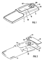
- Figure 1 shows a housing of a handset with attached support member
- Figure 2 shows an assembly process for the support member
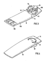
- Figure 3 is a view of the housing side facing the support member
- Figure 4 is a view of the housing side facing away from the support member
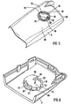
- Figure 5 is a view of the Supporting part facing side of the housing
- Figure 6 is a view of the support member side facing away from the housing.
- Fig. 1 denotes a handset comprising a housing 5 and a support member 10 connected to the housing 5.
- the support member 10 is formed by a rectangular, rounded at the edges of the disc and has an approximately a 3/4 circle forming slot 45, whereby one through the Slot 45 partially enclosed key 15 is offset from the support member 10.
- the approximately 1/4 circular complement of the slot 45 to the full circle forms a resilient connection of the support member 10 with the key 15.
- the support member 10 is longitudinally on the top 90 of the housing 5 in the vicinity of the upper edge 95 of the housing 5 with the housing 5 at the location of the slot 45, which is located at the upper edge 95 of the housing 5 facing the upper edge 100 of the support member 10 is connected.
- the support member 10 is slightly bent in the transverse direction, so that the handset 1 can be clamped by the support member 10 in pants or shirt pockets.
- the handset 1 may be formed as a cordless telephone, as a radio or the like.
- FIG 3 is a view of the housing 5 facing side of the support member 10 is shown, wherein the support member 10 on its side facing the housing 5 has a slot 45 to an approximately 1/4 circular section limiting side wall 50 which also over the 1/4 circular complement of the slot 45 is continued to the full circle.
- the side wall 50 in the approximately 1/4 circular complement of the slot 45 to the full circle at its end facing away from the support member 10 has a side facing away from the side wall 50 to the outside fastening rib 40.
- the approximately 1/4 circular complement of the slot 45 to the full circle forms the upper edge 100 of the support member 10 facing away from the full circle added slot 45.
- the button 15 has on its the housing 5 and the top 100 of the support member 10 side facing in approximately rectangular angled locking lug 25, wherein the angled portion facing towards the top 100 of the support member 10 and extends beyond the slot 45.
- the support member 10 at the opposite end of its upper edge 100 cam 105 which is the attachment of the handset 1 when placed on the housing 5 support member 10 together with the bend of the upper edge 100 of the support member 10 facing away from the lower part 110 to the top 90 of the housing 5 back.
- the side wall 50 is interrupted at the point at which the latching nose 25 protrudes beyond the slot 45.
- FIG 4 shows a view of the side facing away from the housing 5 side of the support member 10 is shown, in which the side wall 50 is also visible due to the perspective view.
- FIG. 5 shows a view of the upper side 90 of the housing 5.
- the upper side 90 of the housing 5 has an approximately circular opening 20.
- a first web 35 protrudes into the opening 20 approximately 1/3-circle.
- a second web 60 also protrudes about 1/3-circular into the opening 20 into it.
- the opening 20 on its side facing away from the top 90 a guide 55 on.
- the guide 55 corresponds to the side wall 50 of the support member 10 and forms an approximately 3/4 circular groove into which the side wall 50 can engage and in which it can perform a guided rotation.
- a first recess 75 for insertion of the locking lug 25 and a second recess 80 for introducing the fixing rib 40 is provided on the side wall of the opening 20 is between the two webs 35 and 60.
- the two recesses 75 and 80 are opposite each other as well as the locking lug 25 and the fixing rib 40 of the support member 10 opposite.
- the second web 60 has in each case a directed into the interior of the housing 5 first and second boundary wall 65 and 70, wherein the second boundary wall 70 at the first recess 75 side facing of the second web 60 and the first boundary wall 65 is arranged on the second recess 80 side facing the second web 60.
- the second boundary wall 70 is wedge-shaped in this case, with increasing distance from the first recess 75, the second boundary wall 70 protrudes into the interior of the housing 5 in increasing measure.
- the first boundary wall 65 projects into the interior of the housing 5 with uniform expansion.
- a recess 30 forming a recess opening remains free, which is offset from the first and the second recess 75 and 80 each 1/4 circular.
- FIG. 6 shows a view of the opening 20 of the housing 5 on the side of the housing 5 facing away from the upper side 90.
- a first, a second and a third boundary web 85, 86 and 87 are arranged at the edge of the opening 20 at the edge of the opening 20, a first, a second and a third boundary web 85, 86 and 87 are arranged at the edge of the opening 20, a first, a second and a third boundary web 85, 86 and 87 are arranged at the edge of the opening 20, a first, a second and a third boundary web 85, 86 and 87 are arranged.
- the first boundary web 85 protrudes into the interior of the housing 5 at the side of the first recess 75 facing away from the second boundary wall 70 and prevents rotation of the support part 10 in this direction by the latching lug 25 on insertion of the latching lug 25 into the first recess 75 blocked.
- the second boundary web 86 protrudes into the interior of the housing 5 and blocks the fastening rib 40 when inserting the fastening rib 40 into the second recess 80 and thus prevents it the rotation of the support member 10 in the clockwise direction in the perspective shown in Figure 6 as well as the first fixing rib 85.
- the same is also effected by the inside of the housing 5 directed third limiting web 87, the first web 35 at a location of the opening 20, the from the first recess 75 is approximately the same distance as the center of the second boundary wall 70, protrudes into the interior of the housing 5.
- the third boundary web 87 is mounted on the side facing away from the first recess 75 of the first boundary web 85 in the vicinity of one end of the guide 55, which from the second boundary wall 70 opposite side of the first recess 75 about 3/4 circular to the first boundary wall 65 extends.
- the third boundary web 87 thus prevents, together with the first boundary wall 65, that the support member 10 can be rotated with its locking lug 25 on the locking opening 30 out in the direction of the second recess 80.
- the three boundary webs 85, 86 and 87 and the first boundary wall 65 can be with the support member 10 in the opening 20 perform an approximately a 1/4 circle forming rotation.
- FIG. 2 shows the procedure required for fastening the carrier part 10 to the housing 5.
- the support member 10 is guided approximately at right angles to the top 90 of the housing 5, so that the latch 25 engages in the first recess 75, the fixing rib 40 in the second recess 80 and the side wall 50 in the guide 55.
- the first and the second boundary web 85 and 86 the direction of rotation for the mounting of the support member 10 according to the direction of the arrow in Figure 2 is fixed in the clockwise direction.
- the locking lug 25 is pushed over the wedge-shaped second boundary wall 70, whereby the key 15 is pressed resiliently to the top 90 of the housing 5.
- the fastening rib 40 pushes onto the side of the first web 35 facing away from the support part 10 or the top side 90 of the housing 5.
- the locking lug 25 engages in the latching opening 30.
- the support member 10 is locked to the housing 5.
- the button 15 To remove the support member 10 of the housing 5, the button 15 must be pressed by the user in the direction of the top 90 of the housing 5, so that the locking lug 25 can be brought out of the latching opening 30. Subsequently, due to the third boundary web 87 and the first boundary wall 65, the support member 10 can be rotated to unlock only in the counterclockwise direction. In this case, the fixing rib 40 is pushed away from the first web 35 to the second recess 80 and the latching nose 25 via the second boundary wall 70 to the first recess 75. After about a 1/4 circular rotation in the counterclockwise direction, the support member 10 can then be removed from the opening 20.
- a correspondingly designed covering device can be placed on the opening 20, which on its side facing the housing 5 as well as the support member 10 with a locking lug, a fastening rib and a side wall provided and in the same way as that Support member 10 may be equipped with a slot 45 and a button 15.
- the key 15 may be additionally equipped with a slot for inserting a coin or a VerFDtechnikmaschinees on the side facing away from the housing 5 of the cover to the assembly and disassembly of the cover to facilitate.
Landscapes
- Engineering & Computer Science (AREA)
- Signal Processing (AREA)
- Computer Networks & Wireless Communication (AREA)
- Telephone Set Structure (AREA)
Description
- Die Erfindung geht von einem Handapparat nach der Gattung des Hauptanspruchs aus.
- Von der Firma Siemens ist das Mobilteil Gigaset 1000 C bekannt, bei dem ein Trageclip von der Rückseite des Mobilteils her auf das Mobilteil gesetzt werden kann. Auf den Seitenflächen des Mobilteils befinden sich Nuten in der Höhe des Displays, in die die Nasen am Bügel des Trageclips einrasten müssen.
- Die
DE-U 29615321 beschreibt einen Handapparat mit einem Gehäuse und einem Trageteil, wobei eine federnd mit dem Trageteil verbundene Taste vorgesehen ist, wobei das Trageteil in eine Öffnung des Gehäuses einsetzbar ist, wobei bei in das Gehäuse eingesetztem Trageteil eine Rastnase der Taste in eine Rastöffnung des Gehäuses rastet und wobei das Trageteil durch eine auf einem ersten Steg des Gehäuses aufliegende Befestigungsrippe am Gehäuse arretiert ist. - Aus der
DE-U 29509559 ist eine Befestigungsvorrichtung für ein Mobiltelefon dargestellt, bei welchem eine Ankuppeleinrichtung und eine Fassung zur lösbaren Aufnahme der Ankuppelvorrichtung vorgesehen ist. - Die
DE-C 4310602 bezieht sich auf einen Befestigungsclip für Kommunikationsgeräte wie das Mobilteil eines schnurlosen Telefons. Um eine glatte Oberfläche des Telefons zu erhalten, aber dennoch eine Clipbefestigung zu ermöglichen, ist der Befestigungsclip versenkbar am Gerät ausgebildet. - Der erfindungsgemäße Handapparat mit den Merkmalen des Hauptanspruchs hat demgegenüber den Vorteil, daß eine einfache und stabile Befestigung des Trageteils realisiert wird, bei der kein zusätzliches Verriegelungselement benötigt wird.
- Durch die in den Unteransprüchen aufgeführten Maßnahmen sind vorteilhafte Weiterbildungen und Verbesserungen des im Hauptanspruch angegebenen Handapparates möglich.
- Vorteilhaft ist, daß die Öffnung des Gehäuses etwa kreisförmig ist und daß zum Befestigen des Trageteils mit dem Gehäuse die Rastnase und die Befestigungsrippe in die Öffnung bringbar sind, durch eine Drehung des Trageteils in der Öffnung die Rastnase in der Rastöffnung einrastbar ist und die Befestigungsrippe auf der dem Trageteil abgewandten Seite des ersten Steges aufschiebbar ist. Auf diese Weise ist die Montage des Trageteils am Gehäuse des Handapparates schnell und einfach möglich.
- Besonders vorteilhaft ist auch, daß zum Entfernen des Trageteils von dem Gehäuse durch Drücken der Taste die Rastnase aus der Rastöffnung bringbar ist und die Befestigungsrippe durch Drehung des Trageteils in der Öffnung vom ersten Steg wegschiebbar ist. Auf diese Weise ist auch die Demontage des Trageteils von dem Gehäuse schnell und einfach möglich, erfordert wenig Kraftaufwand und ist äußerst bedienungsfreundlich.
- Eine besonders einfache Realisierung der Taste wird vorteilhafterweise dadurch bewirkt, daß das Trageteil einen etwa einen 3/4-Kreis bildenden Schlitz aufweist.
- Vorteilhaft ist insbesondere auch, daß das Trageteil an seiner dem Gehäuse zugewandten Seite eine den Schlitz zumindest teilweise begrenzende Seitenwand aufweist, die mit einer entsprechenden in der Öffnung des Gehäuses angeordneten Führung korrespondiert. Auf diese Weise wird die Drehung des Trageteils in der Öffnung des Gehäuses stabilisiert und somit für den Benutzer vereinfacht. Die Montage und Demontage des Trageteils kann somit noch schneller durchgeführt werden.
- Ein weiterer Vorteil besteht darin, daß am Rand der Öffnung ins Innere des Gehäuses gerichtete Begrenzungsstege so angeordnet sind, daß zum Einrasten und Entrasten jeweils eine Drehrichtung für das Trageteil vorgegeben ist. Auf diese Weise wird die Montage und Demontage des Trageteils für den Benutzer weiter vereinfacht.
- Vorteilhaft ist außerdem, daß jeweils eine etwa einen 1/4-Kreis bildende Drehung des Trageteils zum Einrasten und Entrasten erforderlich ist. Auf diese Weise ist die Montage und Demontage des Trageteils besonders schnell möglich.
- Ein Ausführungsbeispiel der Erfindung ist in der Zeichnung dargestellt und in der nachfolgenden Beschreibung näher erläutert. Es zeigen Figur 1 ein Gehäuse eines Handapparates mit aufgesetztem Trageteil, Figur 2 einen Montagevorgang für das Trageteil, Figur 3 eine Ansicht der dem Gehäuse zugewandten Seite des Trageteils, Figur 4 eine Ansicht der dem Gehäuse abgewandten Seite des Trageteils, Figur 5 eine Ansicht der dem Trageteil zugewandten Seite des Gehäuses und Figur 6 eine Ansicht der dem Trageteil abgewandten Seite des Gehäuses.
- In Figur 1 kennzeichnet 1 einen Handapparat, der ein Gehäuse 5 und ein mit dem Gehäuse 5 verbundenes Trageteil 10 umfaßt. Das Trageteil 10 wird durch eine rechteckige, an den Kanten abgerundete Scheibe gebildet und weist einen etwa einen 3/4-Kreis bildenden Schlitz 45 auf, wodurch eine durch den Schlitz 45 teilweise umschlossene Taste 15 vom Trageteil 10 abgesetzt ist. Die etwa 1/4-kreisförmige Ergänzung des Schlitzes 45 zum Vollkreis bildet eine federnde Verbindung des Trageteils 10 mit der Taste 15. Das Trageteil 10 ist in Längsrichtung auf der Oberseite 90 des Gehäuses 5 in der Nähe der Oberkante 95 des Gehäuses 5 mit dem Gehäuse 5 an der Stelle des Schlitzes 45, der sich bei der der Oberkante 95 des Gehäuses 5 zugewandten Oberkante 100 des Trageteils 10 befindet, verbunden. An der Stelle des Schlitzes 45 ist das Trageteil 10 in Querrichtung leicht abgeknickt, so daß der Handapparat 1 durch das Trageteil 10 in Hosen- oder Hemdtaschen geklemmt werden kann. Der Handapparat 1 kann als schnurloses Telefon, als Funkgerät oder dergleichen ausgebildet sein.
- In Figur 3 ist eine Ansicht der dem Gehäuse 5 zugewandten Seite des Trageteils 10 dargestellt, wobei das Trageteil 10 an seiner dem Gehäuse 5 zugewandten Seite eine den Schlitz 45 bis auf einen etwa 1/4-kreisförmigen Abschnitt begrenzende Seitenwand 50 aufweist, die auch über die 1/4-kreisförmige Ergänzung des Schlitzes 45 zum Vollkreis fortgeführt ist. Dabei weist die Seitenwand 50 bei der etwa 1/4-kreisförmigen Ergänzung des Schlitzes 45 zum Vollkreis an ihrem dem Trageteil 10 abgewandten Ende eine von der Seitenwand 50 nach außen abgesetzte Befestigungsrippe 40 auf. Die etwa 1/4-kreisförmige Ergänzung des Schlitzes 45 zum Vollkreis bildet den der Oberkante 100 des Trageteils 10 abgewandten Teil des zum Vollkreis ergänzten Schlitzes 45. Die Taste 15 weist an ihrer dem Gehäuse 5 und der Oberkante 100 des Trageteils 10 zugewandten Seite eine in etwa rechteckig abgewinkelte Rastnase 25 auf, wobei der abgewinkelte Teil in Richtung zur Oberkante 100 des Trageteils 10 weist und über den Schlitz 45 hinausreicht. An seiner dem Gehäuse 5 zugewandten Seite weist das Trageteil 10 an dem seiner Oberkante 100 gegenüberliegenden Ende Nocken 105 auf, die die Befestigung des Handapparates 1 bei auf das Gehäuse 5 aufgesetztem Trageteil 10 zusammen mit der Abwinklung des von der Oberkante 100 des Trageteils 10 abgewandten unteren Teils 110 zur Oberseite 90 des Gehäuses 5 hin unterstützen. Die Seitenwand 50 ist an der Stelle unterbrochen, bei der die Rastnase 25 über den Schlitz 45 hinausragt.
- In Figur 4 ist eine Ansicht der von dem Gehäuse 5 abgewandten Seite des Trageteils 10 dargestellt, bei der die Seitenwand 50 aufgrund der perspektivischen Darstellung ebenfalls zu sehen ist.
- In Figur 5 ist eine Ansicht der Oberseite 90 des Gehäuses 5 dargestellt. In der Nähe der Oberkante 95 des Gehäuses 5 weist die Oberseite 90 des Gehäuses 5 eine etwa kreisförmige Öffnung 20 auf. An der der Oberkante 95 des Gehäuses 5 abgewandten Seite der Öffnung 20 ragt ein erster Steg 35 etwa 1/3-kreisförmig in die Öffnung 20 hinein. An der der Oberkante 95 des Gehäuses 5 zugewandten Seite der Öffnung 20 ragt ein zweiter Steg 60 ebenfalls etwa 1/3-kreisförmig in die Öffnung 20 hinein. Weiterhin weist die Öffnung 20 auf ihrer der Oberseite 90 abgewandten Seite eine Führung 55 auf. Die Führung 55 korrespondiert mit der Seitenwand 50 des Trageteils 10 und bildet eine etwa 3/4-kreisförmige Rille, in die die Seitenwand 50 greifen kann und in der sie eine geführte Drehung vollziehen kann. An der Seitenwand der Öffnung 20 ist zwischen den beiden Stegen 35 und 60 eine erste Aussparung 75 zur Einführung der Rastnase 25 und eine zweite Aussparung 80 zur Einführung der Befestigungsrippe 40 vorgesehen. Die beiden Aussparungen 75 und 80 liegen einander genauso wie die Rastnase 25 und die Befestigungsrippe 40 des Trageteils 10 gegenüber. Der zweite Steg 60 weist jeweils eine ins Innere des Gehäuses 5 gerichtete erste und zweite Begrenzungswand 65 und 70 auf, wobei die zweite Begrenzungswand 70 an der der ersten Aussparung 75 zugewandten Seite des zweiten Steges 60 und die erste Begrenzungswand 65 an der der zweiten Aussparung 80 zugewandten Seite des zweiten Steges 60 angeordnet ist. Die zweite Begrenzungswand 70 ist dabei keilförmig ausgebildet, wobei mit zunehmenden Abstand von der ersten Aussparung 75 die zweite Begrenzungswand 70 in zunehmenden Maße ins Innere des Gehäuses 5 hineinragt. Die erste Begrenzungswand 65 ragt hingegen mit gleichmäßiger Ausdehnung ins Innere des Gehäuses 5 hinein. Zwischen der ersten und der zweiten Begrenzungswand 65 und 70 bleibt eine eine Rastöffnung 30 bildende Aussparung frei, die von der ersten und der zweiten Aussparung 75 und 80 jeweils 1/4-kreisförmig abgesetzt ist.
- In Figur 6 ist eine Ansicht der Öffnung 20 des Gehäuses 5 auf der der Oberseite 90 abgewandten Seite des Gehäuses 5 dargestellt. Dabei sind am Rand der Öffnung 20 ein erster, ein zweiter und ein dritter Begrenzungssteg 85, 86 und 87 angeordnet. Der erste Begrenzungssteg 85 ragt dabei an der der zweiten Begrenzungswand 70 abgewandten Seite der ersten Aussparung 75 ins Innere des Gehäuses 5 hinein und verhindert eine Drehung des Trageteils 10 in diese Richtung, indem sie beim Einsetzen der Rastnase 25 in die erste Aussparung 75 die Rastnase 25 blockiert. Zwischen der in Figur 6 nicht sichtbaren zweiten Aussparung 80, die der ersten Aussparung 75 gegenüberliegt und der Rastöffnung 30 ragt der zweite Begrenzungssteg 86 ins Innere des Gehäuses 5 hinein und blokkiert beim Einsetzen der Befestigungsrippe 40 in die zweite Aussparung 80 die Befestigungsrippe 40 und verhindert so die Drehung des Trageteils 10 im Uhrzeigersinn gemäß der in Figur 6 gezeigten Perspektive genauso wie die erste Befestigungsrippe 85. Dasselbe wird auch durch den ins Innere des Gehäuses 5 gerichteten dritten Begrenzungssteg 87 bewirkt, der vom ersten Steg 35 an einer Stelle der Öffnung 20, die von der ersten Aussparung 75 ungefähr den gleichen Abstand aufweist, wie etwa die Mitte der zweiten Begrenzungswand 70, ins Innere des Gehäuses 5 hineinragt. Der dritte Begrenzungssteg 87 ist dabei auf der der ersten Aussparung 75 abgewandten Seite des ersten Begrenzungssteges 85 in der Nähe eines Endes der Führung 55 angebracht, die sich von der der zweiten Begrenzungswand 70 abgewandten Seite der ersten Aussparung 75 etwa 3/4-kreisförmig bis zur ersten Begrenzungswand 65 erstreckt. Der dritte Begrenzungssteg 87 verhindert somit zusammen mit der ersten Begrenzungswand 65, daß das Trageteil 10 mit seiner Rastnase 25 über die Rastöffnung 30 hinaus in Richtung der zweiten Aussparung 80 gedreht werden kann. Durch die drei Begrenzungsstege 85, 86 und 87 und die erste Begrenzungswand 65 läßt sich mit dem Trageteil 10 in der Öffnung 20 eine etwa einen 1/4-Kreis bildende Drehung durchführen.
- Figur 2 zeigt die zum Befestigen des Trageteils 10 mit dem Gehäuse 5 erforderliche Vorgehensweise. Dabei wird das Trageteil 10 in etwa rechtwinklig an die Oberseite 90 des Gehäuses 5 geführt, so daß die Rastnase 25 in die erste Aussparung 75, die Befestigungsrippe 40 in die zweite Aussparung 80 und die Seitenwand 50 in die Führung 55 greift. Durch den ersten und den zweiten Begrenzungssteg 85 und 86 ist die Drehrichtung für die Montage des Trageteils 10 gemäß der Pfeilrichtung in Figur 2 im Uhrzeigersinn festgelegt. Dabei wird die Rastnase 25 über die keilförmige zweite Begrenzungswand 70 geschoben, wodurch die Taste 15 zur Oberseite 90 des Gehäuses 5 hin federnd eingedrückt wird. Gleichzeitig schiebt sich die Befestigungsrippe 40 auf die dem Trageteil 10 bzw. der Oberseite 90 des Gehäuses 5 abgewandten Seite des ersten Steges 35 auf. Nach einer etwa 1/4-kreisförmigen Drehung rastet die Rastnase 25 in die Rastöffnung 30 ein. Durch das Einrasten der Rastnase 25 in die Rastöffnung 30 und die Auflage der Befestigungsrippe 40 auf dem Steg 35 ist das Trageteil 10 mit dem Gehäuse 5 verriegelt. Beim Einrasten wird die Rastnase 25 am Trageteil 10 gespannt und "klickt" deutlich hörbar in der Endlage. Durch diesen Quittungston wird dem Benutzer die Endlage des Trageteils 10 hörbar gemeldet.
- Zum Entfernen des Trageteils 10 von dem Gehäuse 5 muß die Taste 15 vom Benutzer in Richtung zur Oberseite 90 des Gehäuses 5 gedrückt werden, damit die Rastnase 25 aus der Rastöffnung 30 gebracht werden kann. Anschließend kann aufgrund des dritten Begrenzungssteges 87 und der ersten Begrenzungswand 65 das Trageteil 10 zum Entrasten nur im Gegenuhrzeigersinn gedreht werden. Dabei wird die Befestigungsrippe 40 vom ersten Steg 35 zur zweiten Aussparung 80 und die Rastnase 25 über die zweite Begrenzungswand 70 zur ersten Aussparung 75 weggeschoben. Nach etwa einer 1/4-kreisförmigen Drehung gegen den Uhrzeigersinn kann dann das Trageteil 10 aus der Öffnung 20 entnommen werden.
- Die Drehung des Trageteils 10 in der Öffnung 20 des Gehäuses 5 wird durch die Führung der Seitenwand 50 in der Führung 55 erleichtert und stabilisiert. Zur Abdeckung der Öffnung 20 bei entferntem Trageteil 10 kann eine entsprechend ausgebildete Abdeckvorrichtung auf die Öffnung 20 aufgesetzt werden, die an ihrer dem Gehäuse 5 zugewandten Seite genauso wie das Trageteil 10 mit einer Rastnase, einer Befestigungsrippe und einer Seitenwand versehen und auf gleiche Weise wie das Trageteil 10 mit einem Schlitz 45 und einer Taste 15 ausgestattet sein kann. Die Montage bzw. Demontage einer solchen Abdeckvorrichtung erfolgt dann auf die beschriebene Weise, wobei die Taste 15 zusätzlich mit einem Schlitz zum Einbringen einer Münze oder eines Verdrehwerkzeuges auf der dem Gehäuse 5 abgewandten Seite der Abdeckvorrichtung ausgestattet sein kann, um die Montage und Demontage der Abdeckvorrichtung zu erleichtern.
- Es sind jedoch auch einfachere Abdeckvorrichtungen denkbar, die beispielsweise die Öffnung 20 vollständig abdecken und in die erste Aussparung 75 und die zweite Aussparung 80 greifen und selbsthemmend gegen die Seitenwände der Öffnung 20 drücken. Die Verbindung der Abdeckvorrichtung mit dem Gehäuse 5 muß dabei nicht so stabil wie die Verbindung des Trageteils 10 mit dem Gehäuse 5 sein, da sie nicht mit dem Gewicht des Handapparates 1 durch Tragen in einer Hemd- oder Hosentasche belastet wird.
Claims (9)
- Handapparat (1), insbesondere Schnurlostelefon, mit einem Gehäuse (5) und einem Trageteil (10), wobei eine federnd mit dem Trageteil (10) verbundene Taste (15) vorgesehen ist, wobei das Trageteil (10) in eine Öffnung (20) des Gehäuses (5) einsetzbar ist, wobei bei in das Gehäuse eingesetztem Trageteil (10) eine Rastnase (25) der Taste (15) in eine Rastöffnung (30 des Gehäuses (5) rastet und das Trageteil (10) durch eine auf einem ersten Steg (35) des Gehäuses (5) aufliegende Befestigungsrippe (40) an Gehäuse (5) arretiert ist, dadurch gekennzeichnet, dass die Öffnung (20) etwa kreisförmig ist, dass zum Befestigen des Trageteils (10) mit dem Gehäuse (5) die Rastnase (25) und die Befestigungsrippe (40) in die Öffnung (20) bringbar sind, durch eine Drehung des Trageteils (10) in der Öffnung (20) die Rastnase (25) in die Rastöffnung (30) einrastbar ist und die Bofestigungsrippe (40) auf der dem Trageteil (10) abgewandten Seite des ersten Stegs (35) aufschiebbar ist.
- Handapparat (1) nach Anspruch 1, dadurch gekennzeichnet, daß zum Entfernen des Trageteils (10) von dem Gehäuse (5) durch Drücken der Taste (15) die Rastnase (25) aus der Rastöffnung (30) bringbar ist und die Befestigungsrippe (40) durch Drehung des Trageteils (10) in der Öffnung (20) vom ersten Steg (35) wegschiebbar ist.
- Handapparat (1) nach Anspruch 1 oder 2, dadurch gekennzeichnet, daß die Taste (15) durch einen etwa einen 3/4-Kreis bildenden Schlitz (45) des Trageteils (10) gebildet ist.
- Handapparat (1) nach einem der vorherigen Ansprüche, dadurch gekennzeichnet, daß das Trageteil (10) an seiner dem Gehäuse (5) zugewandten Seite eine den Schlitz (45) zumindest teilweise begrenzende Seitenwand (50) aufweist, die mit einer entsprechenden in der Öffnung (20) des Gehäuses (5) angeordneten Führung (55) korrespondiert.
- Handapparat (1) nach einem der vorherigen Ansprüche, dadurch gekennzeichnet, daß der erste Steg (35) in die Öffnung (20) hineinragt und die Befestigungsrippe (40) an der Seitenwand (50) befestigt ist.
- Handapparat (1) nach einem der vorherigen Ansprüche, dadurch gekennzeichnet, daß die Rastöffnung (30) auf einem in die Öffnung (20) hineinragenden zweiten Steg (60) angeordnet ist und durch zwei ins Innere des Gehäuses (5) gerichtete Begrenzungswände (65, 70) gebildet ist, wobei eine der Begrenzungswände (70) zum Einrasten der Rastnase (25) keilförmig ausgebildet ist.
- Handapparat (1) nach einem der vorherigen Ansprüche, dadurch gekennzeichnet, daß in der Öffnung (20) zwischen den Stegen (35, 60) eine erste Aussparung (75) zur Einführung der Rastnase (25) und eine zweite Aussparung (80) zur Einführung der Befestigungsrippe (40) vorgesehen ist.
- Handapparat (1) nach einem der vorherigen Ansprüche, dadurch gekennzeichnet, daß am Rand der Öffnung (20) ins Innere des Gehäuses (5) gerichtete Begrenzungsstege (85, 86, 87) so angeordnet sind, daß zum Einrasten und Entrasten jeweils eine Drehrichtung für das Trageteil (10) vorgegeben ist.
- Handapparat (1) nach einem der vorherigen Ansprüche, dadurch gekennzeichnet, daß jeweils eine etwa einen Viertelkreis bildende Drehung des Trageteils (10) zum Einrasten und Entrasten erforderlich ist.
Applications Claiming Priority (2)
| Application Number | Priority Date | Filing Date | Title |
|---|---|---|---|
| DE19647979 | 1996-11-20 | ||
| DE19647979A DE19647979C1 (de) | 1996-11-20 | 1996-11-20 | Handapparat |
Publications (3)
| Publication Number | Publication Date |
|---|---|
| EP0844771A2 EP0844771A2 (de) | 1998-05-27 |
| EP0844771A3 EP0844771A3 (de) | 2002-05-15 |
| EP0844771B1 true EP0844771B1 (de) | 2007-07-25 |
Family
ID=7812212
Family Applications (1)
| Application Number | Title | Priority Date | Filing Date |
|---|---|---|---|
| EP97117098A Expired - Lifetime EP0844771B1 (de) | 1996-11-20 | 1997-10-02 | Telefonhandapparat |
Country Status (2)
| Country | Link |
|---|---|
| EP (1) | EP0844771B1 (de) |
| DE (2) | DE19647979C1 (de) |
Families Citing this family (3)
| Publication number | Priority date | Publication date | Assignee | Title |
|---|---|---|---|---|
| DE19847017C1 (de) * | 1998-10-13 | 2000-03-09 | Bosch Gmbh Robert | Clipverriegelung mittels Spreizdübelverschluß für tragbaren Telefonapparat |
| US6193546B1 (en) | 1999-03-16 | 2001-02-27 | Ericsson Inc. | Support assembly for personal electronic device and method for using the same |
| GB2364197A (en) * | 2000-06-30 | 2002-01-16 | Nokia Mobile Phones Ltd | Housing assembly for a mobile telephone |
Family Cites Families (6)
| Publication number | Priority date | Publication date | Assignee | Title |
|---|---|---|---|---|
| JPH0756916B2 (ja) * | 1990-06-11 | 1995-06-14 | 松下電器産業株式会社 | 携帯用電子機器 |
| DE4228632C1 (de) * | 1992-08-28 | 1993-07-29 | Grundig E.M.V. Elektro-Mechanische Versuchsanstalt Max Grundig Hollaend. Stiftung & Co Kg, 8510 Fuerth, De | |
| DE4310602C1 (de) * | 1993-03-31 | 1994-05-26 | Siedle & Soehne S | Befestigungsclip für ein tragbares Kommunikations-Gerät |
| US5488759A (en) * | 1994-07-28 | 1996-02-06 | Motorola, Inc. | Detachable clip for a portable electronic device |
| DE29509559U1 (de) * | 1995-06-10 | 1995-08-31 | Tien, Tse-hsiung, Taipeh/T'ai-pei | Befestigungseinrichtung für ein Mobiltelefon |
| DE29615321U1 (de) * | 1996-09-03 | 1996-10-17 | E. Lead Electronic Co. Ltd., Changhua | Abnehmbare Klippvorrichtung |
-
1996
- 1996-11-20 DE DE19647979A patent/DE19647979C1/de not_active Expired - Lifetime
-
1997
- 1997-10-02 EP EP97117098A patent/EP0844771B1/de not_active Expired - Lifetime
- 1997-10-02 DE DE59712863T patent/DE59712863D1/de not_active Expired - Lifetime
Also Published As
| Publication number | Publication date |
|---|---|
| DE19647979C1 (de) | 1998-04-23 |
| EP0844771A3 (de) | 2002-05-15 |
| DE59712863D1 (de) | 2007-09-06 |
| EP0844771A2 (de) | 1998-05-27 |
Similar Documents
| Publication | Publication Date | Title |
|---|---|---|
| DE3609591C2 (de) | ||
| DE29708507U1 (de) | Befestigungsvorrichtung zum Sichern eines Apparats an einem Gürtel | |
| DE68922987T2 (de) | Buchse mit verriegelung. | |
| EP1729377B1 (de) | Verriegelungseinrichtung für Steckverbinder | |
| DE20020983U1 (de) | Vorrichtung zum Verriegeln von miteinander verbundenen Gehäuseteilen eines mehrteiligen Gehäuses | |
| DE2140589A1 (de) | Gehaeuse fuer den bedienungsgriff des schlosses einer fahrzeugtuer | |
| EP0844771A2 (de) | Telefonhandapparat | |
| DE60100223T2 (de) | Elektrische Steckeranordnung mit einer Bajonettverschlussverbindung | |
| WO1997043552A1 (de) | Vorrichtung zur befestigung eines gerätes | |
| EP0080559B1 (de) | Drucktaster für Schalttafeln | |
| DE29718171U1 (de) | Handyclip | |
| DE3610613A1 (de) | Messinstrumenten-gehaeuse | |
| DE1952925C3 (de) | Isoliergehäuse für mit Haltehaken versehene Flachsteckkontakte | |
| EP0670243B1 (de) | Lichteinheit für Fahrzeuge | |
| EP0093236B1 (de) | Gerätestecker | |
| DE3911696C2 (de) | ||
| DE3906421A1 (de) | Verriegelbarer steckverbinder | |
| WO2001049007A1 (de) | Elektrisches gerät mit einem gehäuse | |
| DE102006005111B4 (de) | Telefonhalter für ein Mobiltelefon | |
| DE8010133U1 (de) | Flachsteckhuelse | |
| EP1112895A2 (de) | Verbindung von Telefon und Halterung | |
| DE4434429A1 (de) | Halteanordnung für ein tragbares Gerät, z. B. für ein Handtelefon | |
| DE2608193B2 (de) | Anordnung zur Befestigung elektrischer Baugruppen | |
| EP1023200A1 (de) | Armlehne für einen fahrzeugsitz | |
| DE2412334C2 (de) | Uhr mit zwei miteinander durch eine einrastende Haltevorrichtung verbundenen Teilen |
Legal Events
| Date | Code | Title | Description |
|---|---|---|---|
| PUAI | Public reference made under article 153(3) epc to a published international application that has entered the european phase |
Free format text: ORIGINAL CODE: 0009012 |
|
| AK | Designated contracting states |
Kind code of ref document: A2 Designated state(s): AT BE CH DE DK ES FI FR GB GR IE IT LI LU MC NL PT SE |
|
| AX | Request for extension of the european patent |
Free format text: AL;LT;LV;RO;SI |
|
| PUAL | Search report despatched |
Free format text: ORIGINAL CODE: 0009013 |
|
| AK | Designated contracting states |
Kind code of ref document: A3 Designated state(s): AT BE CH DE DK ES FI FR GB GR IE IT LI LU MC NL PT SE |
|
| AX | Request for extension of the european patent |
Free format text: AL;LT;LV;RO;SI |
|
| RIC1 | Information provided on ipc code assigned before grant |
Free format text: 7H 04M 1/03 A, 7H 04M 1/04 B, 7A 45F 5/02 B |
|
| 17P | Request for examination filed |
Effective date: 20021115 |
|
| AKX | Designation fees paid |
Designated state(s): DE FR GB IT |
|
| 17Q | First examination report despatched |
Effective date: 20040330 |
|
| GRAP | Despatch of communication of intention to grant a patent |
Free format text: ORIGINAL CODE: EPIDOSNIGR1 |
|
| GRAS | Grant fee paid |
Free format text: ORIGINAL CODE: EPIDOSNIGR3 |
|
| GRAA | (expected) grant |
Free format text: ORIGINAL CODE: 0009210 |
|
| RAP1 | Party data changed (applicant data changed or rights of an application transferred) |
Owner name: IPCOM GMBH & CO. KG |
|
| AK | Designated contracting states |
Kind code of ref document: B1 Designated state(s): DE FR GB IT |
|
| REG | Reference to a national code |
Ref country code: GB Ref legal event code: FG4D Free format text: NOT ENGLISH |
|
| REF | Corresponds to: |
Ref document number: 59712863 Country of ref document: DE Date of ref document: 20070906 Kind code of ref document: P |
|
| GBT | Gb: translation of ep patent filed (gb section 77(6)(a)/1977) |
Effective date: 20071005 |
|
| ET | Fr: translation filed | ||
| PLBE | No opposition filed within time limit |
Free format text: ORIGINAL CODE: 0009261 |
|
| STAA | Information on the status of an ep patent application or granted ep patent |
Free format text: STATUS: NO OPPOSITION FILED WITHIN TIME LIMIT |
|
| 26N | No opposition filed |
Effective date: 20080428 |
|
| REG | Reference to a national code |
Ref country code: FR Ref legal event code: PLFP Year of fee payment: 19 |
|
| REG | Reference to a national code |
Ref country code: FR Ref legal event code: PLFP Year of fee payment: 20 |
|
| PGFP | Annual fee paid to national office [announced via postgrant information from national office to epo] |
Ref country code: DE Payment date: 20161028 Year of fee payment: 20 Ref country code: GB Payment date: 20161025 Year of fee payment: 20 Ref country code: FR Payment date: 20161025 Year of fee payment: 20 |
|
| PGFP | Annual fee paid to national office [announced via postgrant information from national office to epo] |
Ref country code: IT Payment date: 20161025 Year of fee payment: 20 |
|
| REG | Reference to a national code |
Ref country code: DE Ref legal event code: R071 Ref document number: 59712863 Country of ref document: DE |
|
| REG | Reference to a national code |
Ref country code: GB Ref legal event code: PE20 Expiry date: 20171001 |
|
| PG25 | Lapsed in a contracting state [announced via postgrant information from national office to epo] |
Ref country code: GB Free format text: LAPSE BECAUSE OF EXPIRATION OF PROTECTION Effective date: 20171001 |