EP0844447A2 - Verfahren zur Herstellung eines Wärmetauschers und damit hergestellter Wärmetauscher - Google Patents
Verfahren zur Herstellung eines Wärmetauschers und damit hergestellter Wärmetauscher Download PDFInfo
- Publication number
- EP0844447A2 EP0844447A2 EP97118032A EP97118032A EP0844447A2 EP 0844447 A2 EP0844447 A2 EP 0844447A2 EP 97118032 A EP97118032 A EP 97118032A EP 97118032 A EP97118032 A EP 97118032A EP 0844447 A2 EP0844447 A2 EP 0844447A2
- Authority
- EP
- European Patent Office
- Prior art keywords
- pipe
- heat exchanger
- substantially rectilinear
- coil
- plate
- Prior art date
- Legal status (The legal status is an assumption and is not a legal conclusion. Google has not performed a legal analysis and makes no representation as to the accuracy of the status listed.)
- Withdrawn
Links
Images


Classifications
-
- B—PERFORMING OPERATIONS; TRANSPORTING
- B21—MECHANICAL METAL-WORKING WITHOUT ESSENTIALLY REMOVING MATERIAL; PUNCHING METAL
- B21D—WORKING OR PROCESSING OF SHEET METAL OR METAL TUBES, RODS OR PROFILES WITHOUT ESSENTIALLY REMOVING MATERIAL; PUNCHING METAL
- B21D53/00—Making other particular articles
- B21D53/02—Making other particular articles heat exchangers or parts thereof, e.g. radiators, condensers fins, headers
- B21D53/08—Making other particular articles heat exchangers or parts thereof, e.g. radiators, condensers fins, headers of both metal tubes and sheet metal
-
- F—MECHANICAL ENGINEERING; LIGHTING; HEATING; WEAPONS; BLASTING
- F25—REFRIGERATION OR COOLING; COMBINED HEATING AND REFRIGERATION SYSTEMS; HEAT PUMP SYSTEMS; MANUFACTURE OR STORAGE OF ICE; LIQUEFACTION SOLIDIFICATION OF GASES
- F25B—REFRIGERATION MACHINES, PLANTS OR SYSTEMS; COMBINED HEATING AND REFRIGERATION SYSTEMS; HEAT PUMP SYSTEMS
- F25B39/00—Evaporators; Condensers
- F25B39/02—Evaporators
-
- F—MECHANICAL ENGINEERING; LIGHTING; HEATING; WEAPONS; BLASTING
- F28—HEAT EXCHANGE IN GENERAL
- F28F—DETAILS OF HEAT-EXCHANGE AND HEAT-TRANSFER APPARATUS, OF GENERAL APPLICATION
- F28F1/00—Tubular elements; Assemblies of tubular elements
- F28F1/10—Tubular elements and assemblies thereof with means for increasing heat-transfer area, e.g. with fins, with projections, with recesses
- F28F1/12—Tubular elements and assemblies thereof with means for increasing heat-transfer area, e.g. with fins, with projections, with recesses the means being only outside the tubular element
- F28F1/14—Tubular elements and assemblies thereof with means for increasing heat-transfer area, e.g. with fins, with projections, with recesses the means being only outside the tubular element and extending longitudinally
- F28F1/22—Tubular elements and assemblies thereof with means for increasing heat-transfer area, e.g. with fins, with projections, with recesses the means being only outside the tubular element and extending longitudinally the means having portions engaging further tubular elements
-
- F—MECHANICAL ENGINEERING; LIGHTING; HEATING; WEAPONS; BLASTING
- F25—REFRIGERATION OR COOLING; COMBINED HEATING AND REFRIGERATION SYSTEMS; HEAT PUMP SYSTEMS; MANUFACTURE OR STORAGE OF ICE; LIQUEFACTION SOLIDIFICATION OF GASES
- F25B—REFRIGERATION MACHINES, PLANTS OR SYSTEMS; COMBINED HEATING AND REFRIGERATION SYSTEMS; HEAT PUMP SYSTEMS
- F25B2339/00—Details of evaporators; Details of condensers
- F25B2339/02—Details of evaporators
- F25B2339/023—Evaporators consisting of one or several sheets on one face of which is fixed a refrigerant carrying coil
-
- F—MECHANICAL ENGINEERING; LIGHTING; HEATING; WEAPONS; BLASTING
- F28—HEAT EXCHANGE IN GENERAL
- F28F—DETAILS OF HEAT-EXCHANGE AND HEAT-TRANSFER APPARATUS, OF GENERAL APPLICATION
- F28F2210/00—Heat exchange conduits
- F28F2210/10—Particular layout, e.g. for uniform temperature distribution
-
- F—MECHANICAL ENGINEERING; LIGHTING; HEATING; WEAPONS; BLASTING
- F28—HEAT EXCHANGE IN GENERAL
- F28F—DETAILS OF HEAT-EXCHANGE AND HEAT-TRANSFER APPARATUS, OF GENERAL APPLICATION
- F28F2275/00—Fastening; Joining
- F28F2275/02—Fastening; Joining by using bonding materials; by embedding elements in particular materials
- F28F2275/025—Fastening; Joining by using bonding materials; by embedding elements in particular materials by using adhesives
Definitions
- the present invention refers to a method for producing a heat exchanger adapted to be used in a refrigeration apparatus, in particular household-type or similar refrigerating equipment, as well as a heat exchanger produced with such a method.
- An advantageous, but not sole application of this heat exchanger is as a so-called static evaporator, ie.an evaporator operating by natural convection, that is adhesive-bonded to inner walls of the refrigeration apparatus.
- Roll Bond TM technique
- the second technological method calls on the contrary for the use of a pipe having a circular or a D-shaped cross-section and curved in the form of a flat coil with substantially rectilinear sections and related connecting or union bends (180°-elbows), said coil being subsequently adhesive-bonded on one or more walls of the inner compartments of the refrigeration apparatus.
- Aluminium alloys are generally used in the evaporators produced with such technologies, so that, owing to well-known soldering or brazing difficulties, a certain criticality is always present at the points in which the evaporators are joined to the remaining parts of the refrigerating circuit of the apparatus. Furthermore, the costs of the above mentioned raw material, ie. aluminium, are subject to quite frequent price fluctuations, which may be even of a quite considerable extent and clearly affect in a negative manner both production costs and the overall manufacturing economics.
- a method of producing heat exchangers is also known in which the pipe being bent into a coil is made of an iron alloy, which undoubtedly features technological and economic uncertainties to a much smaller extent than aluminium alloys. To the purpose of compensating for the smaller heat conductivity of the material, the heat-exchange surface of the pipe must however be increased.
- a commonly known technique consists in caulking the substantially rectilinear sections of the flat coil on a plate, which is also made of an iron alloy and is coplanar with, ie. lies in the same plane as said coil.
- the toughness of iron alloys makes it difficult for the evaporator to be compliantly adapted to the above cited walls.
- the subject covered by the present invention therefore relates to a manufacturing method and a heat exchanger produced with such a method, both having the characteristics as substantially recited in the appended claims.
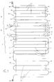
- a static evaporator for the freezing compartment of a household refrigeration appliance is made starting from a pipe 10, which is made of an iron alloy material and has a circular cross-section, wherein such a pipe is bent so as to obtain a desired flat-coil configuration that is formed by a plurality of substantially rectilinear and parallel sections 20 and union elbows 30 provided between each one of said sections and the next one.
- the coiled pipe 1 is arranged on a quadrilateral plate 50 that is also made of an iron alloy material, is substantially coplanar with the pipe 10 and is provided with a plurality of parallel grooves 60 extending between two mutually opposing side edges 70 and 80 thereof.
- evaporators 41 and 42 each one of which is made starting from semi-finished products with the above described materials and manufacturing operations.
- the evaporators 41 and 42 (hereinafter called simply freezer evaporator and cold storage evaporator, respectively) are made starting from and consist of a single pipe 10 and comprise two plates that are generally indicated at 51 and 52, respectively.
- the freezer evaporator 41 comprises three zones A, B, C that are made up by substantially rectilinear and parallel sections 21 of the pipe 10, with the related union elbows 31, and the therewith associated portions of the plate 51.
- it is the substantially rectilinear of the pipe 10 which are indicated with the reference numerals 15 and 16, and whose longitudinal axes are indicated with X-X and Y-Y, respectively, that are particularly highlighted in the drawings.
- the cold storage evaporator 42 is on the contrary formed by a single group of substantially rectilinear, parallel sections 22 and related union elbows 32 of the pipe 10, as well as by the therewith associated plate 52.
- the hydraulic connection of the two evaporators 41 and 42 with each other is brought about by a pipe union 17 arranged outside the outer contour of the plates 51 and 52, for instance perpendicularly to the above mentioned rectilinear sections 21 and 22 of the pipe 10.
- the zones A, B and C of the freezer evaporator 41 are therefore so shaped as to be able to more fittingly conform to the outer surface (not exposed to view) of the walls 91, 92 and 93 of the freezing compartment 90 of a household combined freezer-fridge refrigeration appliance.
- the above mentioned substantially rectilinear, parallel sections 15 and 16 of the pipe 10 are so arranged as to be eventually positioned along the corners of the compartment 90 that are formed by the walls 91, 92 and 92, 93, respectively.
- the torques used to clamp the pipe end portions in the vices 12 and 14 are of course so selected as to prevent the pipe 10 from being damaged, ie.
- the mechanical properties of the iron alloys and the wall thicknesses of both the pipe 10 and the plate 50 are so selected as to prevent the freezer evaporator 41 from showing any tendency to lose its C-shaped configuration, ie. to resume its original flat shape, alter the above mentioned operations of torsional deformation and right-angle bending.
- the operation can be started to bend in the required manner the sections of the pipe 10 that are not associated with the plates 51 and 52, and in particular the pipe union 17, so as to conform them to the particular requirements placed by the other parts that make up the refrigeration apparatus.
- this phase of the manufacturing process is a substantially conventional one, so that no further explanation is felt to be necessary here.
- the zones A, B, C of the freezer evaporator 41 are attached by adhesive-bonding to the unexposed (ie. not in view) surface of the afore mentioned walls 91, 92 and 93 of the freezing compartment 90, while the cold storage evaporator 42 is attached by adhesive-bonding to the rear wall 96 of the cold storage compartment 95 (see Figure 4), wherein also these adhesive-bonding operations are carried out in accordance with techniques that are well-known to those skilled in the art.
Landscapes
- Engineering & Computer Science (AREA)
- Physics & Mathematics (AREA)
- Mechanical Engineering (AREA)
- Thermal Sciences (AREA)
- General Engineering & Computer Science (AREA)
- Geometry (AREA)
- Heat-Exchange Devices With Radiators And Conduit Assemblies (AREA)
- Separation By Low-Temperature Treatments (AREA)
Applications Claiming Priority (2)
| Application Number | Priority Date | Filing Date | Title |
|---|---|---|---|
| ITPN960065 | 1996-11-26 | ||
| ITPN960065 IT1289400B1 (it) | 1996-11-26 | 1996-11-26 | Metodo per produrre uno scambiatore di calore per un apparecchio refrigerante e scambiatore di calore cosi' prodotto |
Publications (2)
| Publication Number | Publication Date |
|---|---|
| EP0844447A2 true EP0844447A2 (de) | 1998-05-27 |
| EP0844447A3 EP0844447A3 (de) | 2000-04-12 |
Family
ID=11395201
Family Applications (1)
| Application Number | Title | Priority Date | Filing Date |
|---|---|---|---|
| EP97118032A Withdrawn EP0844447A3 (de) | 1996-11-26 | 1997-10-17 | Verfahren zur Herstellung eines Wärmetauschers und damit hergestellter Wärmetauscher |
Country Status (2)
| Country | Link |
|---|---|
| EP (1) | EP0844447A3 (de) |
| IT (1) | IT1289400B1 (de) |
Cited By (6)
| Publication number | Priority date | Publication date | Assignee | Title |
|---|---|---|---|---|
| EP0917919A3 (de) * | 1997-11-06 | 2001-04-11 | Whirlpool Corporation | Herstellungsverfahren eines einteiligen Verdampfers, und der hergestellte Verdampfer |
| WO2002053371A1 (de) * | 2001-01-08 | 2002-07-11 | Flamm Aktiengesellschaft | Verfahren zum herstellen von verdampferplatten |
| WO2003001135A1 (es) * | 2001-05-01 | 2003-01-03 | Romero Beltran Julian | Intercambiador de calor del tipo placa-tubo |
| WO2006069783A1 (de) * | 2004-12-28 | 2006-07-06 | Liebherr-Hausgeräte Ochsenhausen GmbH | Kühl- und gefriergerät |
| EP1746366A1 (de) * | 2005-07-22 | 2007-01-24 | Liebherr-Hausgeräte Ochsenhausen GmbH | Rohr-/Blechverflüssiger für Kühl- und/oder Gefriergeräte |
| DE102016003547A1 (de) * | 2016-03-22 | 2017-09-28 | Liebherr-Hausgeräte Ochsenhausen GmbH | Kühl- und/oder Gefriergerät |
Citations (6)
| Publication number | Priority date | Publication date | Assignee | Title |
|---|---|---|---|---|
| US2297219A (en) * | 1938-02-03 | 1942-09-29 | Hintze Rudolf | Evaporator for refrigerating apparatus of the compression type |
| US2306772A (en) * | 1940-03-12 | 1942-12-29 | Mullins Mfg Corp | Sheet and tube evaporator |
| US2562638A (en) * | 1947-05-02 | 1951-07-31 | Nash Kelvinator Corp | Refrigerated tank |
| US2741095A (en) * | 1952-10-07 | 1956-04-10 | Gen Motors Corp | Refrigeratior having multiple section evaporator |
| US2940737A (en) * | 1955-04-08 | 1960-06-14 | Houdaille Industries Inc | Heat exchanger |
| FR2631688A3 (fr) * | 1988-05-04 | 1989-11-24 | Whirlpool Int | Evaporateur pour un refrigerateur |
-
1996
- 1996-11-26 IT ITPN960065 patent/IT1289400B1/it active IP Right Grant
-
1997
- 1997-10-17 EP EP97118032A patent/EP0844447A3/de not_active Withdrawn
Patent Citations (6)
| Publication number | Priority date | Publication date | Assignee | Title |
|---|---|---|---|---|
| US2297219A (en) * | 1938-02-03 | 1942-09-29 | Hintze Rudolf | Evaporator for refrigerating apparatus of the compression type |
| US2306772A (en) * | 1940-03-12 | 1942-12-29 | Mullins Mfg Corp | Sheet and tube evaporator |
| US2562638A (en) * | 1947-05-02 | 1951-07-31 | Nash Kelvinator Corp | Refrigerated tank |
| US2741095A (en) * | 1952-10-07 | 1956-04-10 | Gen Motors Corp | Refrigeratior having multiple section evaporator |
| US2940737A (en) * | 1955-04-08 | 1960-06-14 | Houdaille Industries Inc | Heat exchanger |
| FR2631688A3 (fr) * | 1988-05-04 | 1989-11-24 | Whirlpool Int | Evaporateur pour un refrigerateur |
Cited By (8)
| Publication number | Priority date | Publication date | Assignee | Title |
|---|---|---|---|---|
| EP0917919A3 (de) * | 1997-11-06 | 2001-04-11 | Whirlpool Corporation | Herstellungsverfahren eines einteiligen Verdampfers, und der hergestellte Verdampfer |
| WO2002053371A1 (de) * | 2001-01-08 | 2002-07-11 | Flamm Aktiengesellschaft | Verfahren zum herstellen von verdampferplatten |
| WO2003001135A1 (es) * | 2001-05-01 | 2003-01-03 | Romero Beltran Julian | Intercambiador de calor del tipo placa-tubo |
| US7140425B2 (en) | 2001-05-01 | 2006-11-28 | Julian Romero-Beltran | Plate-tube type heat exchanger |
| CN1297795C (zh) * | 2001-05-01 | 2007-01-31 | 朱利安·罗梅罗-贝尔特伦 | 管板型热交换器 |
| WO2006069783A1 (de) * | 2004-12-28 | 2006-07-06 | Liebherr-Hausgeräte Ochsenhausen GmbH | Kühl- und gefriergerät |
| EP1746366A1 (de) * | 2005-07-22 | 2007-01-24 | Liebherr-Hausgeräte Ochsenhausen GmbH | Rohr-/Blechverflüssiger für Kühl- und/oder Gefriergeräte |
| DE102016003547A1 (de) * | 2016-03-22 | 2017-09-28 | Liebherr-Hausgeräte Ochsenhausen GmbH | Kühl- und/oder Gefriergerät |
Also Published As
| Publication number | Publication date |
|---|---|
| ITPN960065A1 (it) | 1998-05-26 |
| EP0844447A3 (de) | 2000-04-12 |
| IT1289400B1 (it) | 1998-10-02 |
Similar Documents
| Publication | Publication Date | Title |
|---|---|---|
| US6928833B2 (en) | Finned tube for heat exchangers, heat exchanger, process for producing heat exchanger finned tube, and process for fabricating heat exchanger | |
| US1987422A (en) | Method of making heat exchange apparatus | |
| KR20070065887A (ko) | 열 교환기 | |
| JP2009133500A (ja) | 空気調和機 | |
| US2514469A (en) | Method of fabricating heat exchangers | |
| US2567716A (en) | Heat exchange unit | |
| EP0844447A2 (de) | Verfahren zur Herstellung eines Wärmetauschers und damit hergestellter Wärmetauscher | |
| RU2350872C2 (ru) | Теплообменник и способ его изготовления | |
| EP1974851A2 (de) | Verfahren zur Herstellung von Wärmetauschern, die als statische Gestellverdampfer in Kühl- oder Gefrierschränken benutzt werden können | |
| US7181929B2 (en) | Finned tube for heat exchangers, heat exchanger, apparatus for fabricating heat exchanger finned tube and process for fabricating heat exchanger finned tube | |
| US2354131A (en) | Refrigerating apparatus | |
| HU212748B (en) | Method of making evaporator for compressor-type refrigerating machine | |
| US2779168A (en) | Refrigerating apparatus | |
| EP0866289A2 (de) | Wärmetauscher wie ein Verflüssiger und/oder Verdampfer für Kältegerät | |
| CN107702388B (zh) | 一种冷凝器及其制造工装和制造方法 | |
| JP6797304B2 (ja) | 熱交換器及び空気調和機 | |
| US2773301A (en) | Method of making heat exchange unit | |
| US1996808A (en) | Refrigerating apparatus | |
| JP2001091180A (ja) | プレートフィンチューブ型熱交換器およびその製造方法とそれを用いた冷蔵庫 | |
| WO2004053414A1 (en) | Finned tube for heat exchangers, heat exchanger, apparatus for fabricating heat exchanger finned tube and process for fabricating heat exchanger finned tube | |
| US2157127A (en) | Evaporator | |
| US2067208A (en) | Refrigerating apparatus | |
| KR100402883B1 (ko) | 냉장고용 일체형 증발기 지지구조 | |
| JPH028666A (ja) | 冷媒分配器 | |
| US1929952A (en) | Cooling units for refrigeration purposes and method of making same |
Legal Events
| Date | Code | Title | Description |
|---|---|---|---|
| PUAI | Public reference made under article 153(3) epc to a published international application that has entered the european phase |
Free format text: ORIGINAL CODE: 0009012 |
|
| AK | Designated contracting states |
Kind code of ref document: A2 Designated state(s): DE ES FR GB IT |
|
| AX | Request for extension of the european patent |
Free format text: AL;LT;LV;RO;SI |
|
| PUAL | Search report despatched |
Free format text: ORIGINAL CODE: 0009013 |
|
| AK | Designated contracting states |
Kind code of ref document: A3 Designated state(s): AT BE CH DE DK ES FI FR GB GR IE IT LI LU MC NL PT SE |
|
| AX | Request for extension of the european patent |
Free format text: AL;LT;LV;RO;SI |
|
| 17P | Request for examination filed |
Effective date: 20000621 |
|
| AKX | Designation fees paid |
Free format text: DE ES FR GB IT |
|
| 17Q | First examination report despatched |
Effective date: 20010306 |
|
| STAA | Information on the status of an ep patent application or granted ep patent |
Free format text: STATUS: THE APPLICATION IS DEEMED TO BE WITHDRAWN |
|
| 18D | Application deemed to be withdrawn |
Effective date: 20020221 |