EP0843182B1 - Hindernis-Sensor mit Kollimation und Fokussierung der emittierten Wellen - Google Patents
Hindernis-Sensor mit Kollimation und Fokussierung der emittierten Wellen Download PDFInfo
- Publication number
- EP0843182B1 EP0843182B1 EP97119777A EP97119777A EP0843182B1 EP 0843182 B1 EP0843182 B1 EP 0843182B1 EP 97119777 A EP97119777 A EP 97119777A EP 97119777 A EP97119777 A EP 97119777A EP 0843182 B1 EP0843182 B1 EP 0843182B1
- Authority
- EP
- European Patent Office
- Prior art keywords
- obstacle sensor
- sensor according
- lens
- diode
- anyone
- Prior art date
- Legal status (The legal status is an assumption and is not a legal conclusion. Google has not performed a legal analysis and makes no representation as to the accuracy of the status listed.)
- Expired - Lifetime
Links
- 230000005670 electromagnetic radiation Effects 0.000 claims description 10
- 230000033228 biological regulation Effects 0.000 claims description 9
- 239000003989 dielectric material Substances 0.000 claims description 8
- 238000004458 analytical method Methods 0.000 claims description 7
- 230000003287 optical effect Effects 0.000 claims description 6
- 230000001427 coherent effect Effects 0.000 claims description 3
- 229910000831 Steel Inorganic materials 0.000 claims description 2
- 229910052782 aluminium Inorganic materials 0.000 claims description 2
- XAGFODPZIPBFFR-UHFFFAOYSA-N aluminium Chemical compound [Al] XAGFODPZIPBFFR-UHFFFAOYSA-N 0.000 claims description 2
- 239000006185 dispersion Substances 0.000 claims description 2
- 239000010959 steel Substances 0.000 claims description 2
- 230000005855 radiation Effects 0.000 description 13
- 229910052751 metal Inorganic materials 0.000 description 8
- 239000002184 metal Substances 0.000 description 8
- 230000005540 biological transmission Effects 0.000 description 6
- 238000010586 diagram Methods 0.000 description 6
- 239000000463 material Substances 0.000 description 4
- 239000004033 plastic Substances 0.000 description 3
- 229920003023 plastic Polymers 0.000 description 3
- 238000004891 communication Methods 0.000 description 2
- 230000000694 effects Effects 0.000 description 2
- 230000003094 perturbing effect Effects 0.000 description 2
- 239000000243 solution Substances 0.000 description 2
- 229910001218 Gallium arsenide Inorganic materials 0.000 description 1
- VVQNEPGJFQJSBK-UHFFFAOYSA-N Methyl methacrylate Chemical compound COC(=O)C(C)=C VVQNEPGJFQJSBK-UHFFFAOYSA-N 0.000 description 1
- 229920005372 Plexiglas® Polymers 0.000 description 1
- 239000004698 Polyethylene Substances 0.000 description 1
- 239000004809 Teflon Substances 0.000 description 1
- 229920006362 Teflon® Polymers 0.000 description 1
- 238000009825 accumulation Methods 0.000 description 1
- 239000004411 aluminium Substances 0.000 description 1
- 230000003321 amplification Effects 0.000 description 1
- 230000015572 biosynthetic process Effects 0.000 description 1
- 239000000919 ceramic Substances 0.000 description 1
- 239000012141 concentrate Substances 0.000 description 1
- 238000007405 data analysis Methods 0.000 description 1
- 239000000428 dust Substances 0.000 description 1
- 230000008030 elimination Effects 0.000 description 1
- 238000003379 elimination reaction Methods 0.000 description 1
- 238000005516 engineering process Methods 0.000 description 1
- 238000001914 filtration Methods 0.000 description 1
- 239000011521 glass Substances 0.000 description 1
- 230000017525 heat dissipation Effects 0.000 description 1
- 239000012535 impurity Substances 0.000 description 1
- 238000002347 injection Methods 0.000 description 1
- 239000007924 injection Substances 0.000 description 1
- 238000001746 injection moulding Methods 0.000 description 1
- 238000009413 insulation Methods 0.000 description 1
- 230000005499 meniscus Effects 0.000 description 1
- 238000000034 method Methods 0.000 description 1
- 238000003199 nucleic acid amplification method Methods 0.000 description 1
- 229920000728 polyester Polymers 0.000 description 1
- -1 polyethylene Polymers 0.000 description 1
- 229920000573 polyethylene Polymers 0.000 description 1
- 239000010453 quartz Substances 0.000 description 1
- 230000001105 regulatory effect Effects 0.000 description 1
- VYPSYNLAJGMNEJ-UHFFFAOYSA-N silicon dioxide Inorganic materials O=[Si]=O VYPSYNLAJGMNEJ-UHFFFAOYSA-N 0.000 description 1
Images

Classifications
-
- H—ELECTRICITY
- H01—ELECTRIC ELEMENTS
- H01Q—ANTENNAS, i.e. RADIO AERIALS
- H01Q19/00—Combinations of primary active antenna elements and units with secondary devices, e.g. with quasi-optical devices, for giving the antenna a desired directional characteristic
- H01Q19/06—Combinations of primary active antenna elements and units with secondary devices, e.g. with quasi-optical devices, for giving the antenna a desired directional characteristic using refracting or diffracting devices, e.g. lens
- H01Q19/08—Combinations of primary active antenna elements and units with secondary devices, e.g. with quasi-optical devices, for giving the antenna a desired directional characteristic using refracting or diffracting devices, e.g. lens for modifying the radiation pattern of a radiating horn in which it is located
-
- G—PHYSICS
- G01—MEASURING; TESTING
- G01S—RADIO DIRECTION-FINDING; RADIO NAVIGATION; DETERMINING DISTANCE OR VELOCITY BY USE OF RADIO WAVES; LOCATING OR PRESENCE-DETECTING BY USE OF THE REFLECTION OR RERADIATION OF RADIO WAVES; ANALOGOUS ARRANGEMENTS USING OTHER WAVES
- G01S17/00—Systems using the reflection or reradiation of electromagnetic waves other than radio waves, e.g. lidar systems
-
- G—PHYSICS
- G01—MEASURING; TESTING
- G01S—RADIO DIRECTION-FINDING; RADIO NAVIGATION; DETERMINING DISTANCE OR VELOCITY BY USE OF RADIO WAVES; LOCATING OR PRESENCE-DETECTING BY USE OF THE REFLECTION OR RERADIATION OF RADIO WAVES; ANALOGOUS ARRANGEMENTS USING OTHER WAVES
- G01S13/00—Systems using the reflection or reradiation of radio waves, e.g. radar systems; Analogous systems using reflection or reradiation of waves whose nature or wavelength is irrelevant or unspecified
- G01S13/88—Radar or analogous systems specially adapted for specific applications
- G01S13/93—Radar or analogous systems specially adapted for specific applications for anti-collision purposes
- G01S13/931—Radar or analogous systems specially adapted for specific applications for anti-collision purposes of land vehicles
-
- G—PHYSICS
- G01—MEASURING; TESTING
- G01S—RADIO DIRECTION-FINDING; RADIO NAVIGATION; DETERMINING DISTANCE OR VELOCITY BY USE OF RADIO WAVES; LOCATING OR PRESENCE-DETECTING BY USE OF THE REFLECTION OR RERADIATION OF RADIO WAVES; ANALOGOUS ARRANGEMENTS USING OTHER WAVES
- G01S7/00—Details of systems according to groups G01S13/00, G01S15/00, G01S17/00
- G01S7/02—Details of systems according to groups G01S13/00, G01S15/00, G01S17/00 of systems according to group G01S13/00
- G01S7/03—Details of HF subsystems specially adapted therefor, e.g. common to transmitter and receiver
- G01S7/032—Constructional details for solid-state radar subsystems
-
- G—PHYSICS
- G01—MEASURING; TESTING
- G01S—RADIO DIRECTION-FINDING; RADIO NAVIGATION; DETERMINING DISTANCE OR VELOCITY BY USE OF RADIO WAVES; LOCATING OR PRESENCE-DETECTING BY USE OF THE REFLECTION OR RERADIATION OF RADIO WAVES; ANALOGOUS ARRANGEMENTS USING OTHER WAVES
- G01S13/00—Systems using the reflection or reradiation of radio waves, e.g. radar systems; Analogous systems using reflection or reradiation of waves whose nature or wavelength is irrelevant or unspecified
- G01S13/88—Radar or analogous systems specially adapted for specific applications
- G01S13/93—Radar or analogous systems specially adapted for specific applications for anti-collision purposes
- G01S13/931—Radar or analogous systems specially adapted for specific applications for anti-collision purposes of land vehicles
- G01S2013/9325—Radar or analogous systems specially adapted for specific applications for anti-collision purposes of land vehicles for inter-vehicle distance regulation, e.g. navigating in platoons
Definitions
- the present invention relates to an obstacle sensor operating by collimation and focusing of the emitted wave, which is substantially constituted by: a unit suitable for the generation and reception of electromagnetic radiations, a data analyser/discriminator and by an antenna suitable for the collimation and focusing of the transceived waves. Said antenna performs on the reflected waves, before sending them to the receiving/transmitting part, the same operations carried out on the transmitted waves.
- the invention concerns the micro-wave and millimetric wave devices, and in particular the compact solid-state micro-wave and millimetric wave devices. By the term “millimetric waves" there is intended to indicate the whole millimetric and sub-millimetric system.
- the transceiving unit comprises a transmission part and a receiving part directly connected to the sign analysis part.
- the transmission part generates the radiation while the reception part receives the radiation reflected by the obstacle, generating output signal wherefrom it is possible to determine useful information for the applications of interest, such as, for instance, the speed and the position of the identified objects, the position of a plane, a level, and so on.
- the latter task is performed by the data analysis and processing electronic circuit.
- the microwaves emitted omnidirectionally are transmitted, focused and concentrated in only one coherent and phased beam, while the reflected or echo unidirectional wave, due to the presence of a still or moving obstacle is sensed by the system, and analysed and quantified with respect to the typical behaviour of the diode utilised as a microwave generator, or, and for instance, depending on the difference in frequency shifting typical of GUNN diodes, as energy and temperature change.
- the radars to be used on road vehicles must have well defined requirements suitable to satisfy some basic needs, namely: a radar for motor-vehicles must be small, in order to allow an easy and economical disassembly onboard; it must be able of sensing exactly objects located before the vehicle within a range comprised between 0 and at least 150 m of distance; the total power absorbed for its working must be contained, of the order of some watts; the diameter of the radiation beam emitted must be, at a certain distance, sufficiently small to identify with the utmost precision the position of the object sensed, independently on its being still or moving; it must supply a number of false alarms as small as possible. Besides, the system must be mass-produceable at a low cost.
- the invention solves the problem by means of an obstacle sensor operating by collimation and focusing of the emitted wave, through which the following results are achieved:
- the system is a millimetric small size system of adequate range, with a low power consumption, a very low, substantially insignificant percent of false alarms, which can operate as a signal transceiving antenna with an optimum image definition even at extremely reduced distances (in the order of 1 mm); it may be mass-produced to low costs, with the adoption of one or more lenses, wherein the longitudinal dimension of the antenna is shorter than the focal length of the same optic apparatus, and with the realisation of transceving and analysis electronic circuits of the so-called feed-assembly type, provided with a heat dissipation system for the circuit part.
- the intrinsic advantages of the invention comprise substantially the reduced size of the general structure of the obstacle sensor, its extreme compactness and effectiveness both in normal atmospheric conditions and in particularly severe climate conditions. More specifically, the system can be adopted in the motor-car field for a greater safety of the vehicles and their passengers in the road traffic, and to lighten and facilitate the activity of drivers in particular road conditions, such as: poor visibility during the night, presence of fog, rain, snow, and so on.
- the invention acts, by means of signals or automatic intervention measures, in the presence of obstacles or in case of a too close drive with respect to other vehicles.
- the same invention may be advantageously used also for watch and traffic control systems.
- the systems operates always and in any case within the frame and in the respect of the safety norms in force at present for the electronic systems.
- the figures refer to an obstacle sensor operating by collimation and focusing of the emitted wave, substantially constituted by a microwave generator represented by an IMPATT or GUNN in GaAs or InP technology diode, kept at a constant temperature and protected by means of adequate insulations.
- GUNN diode After a first coordination stage, the waves generated by said diode pass through one or several lenses from dielectric material, or artificial dielectric, of high dielectric constant, permeable to electromagnetic radiation and resistant against weathering.
- such lenses may have a hemispheric, aspherical, elliptic, concave, convex, biconvex, stepped shape.
- the optical apparatus is realisable from plastic material, plexiglass, ceramic, quartz, glass, polyethylene, polyester, teflon and the like, and in any case from dielectric material or artificial dielectric with a high dielectric constant, permeable to electromagnetic radiation and resistant against weathering, very homogeneous and compact, free from impurities and/or inclusions.
- the function of the optical apparatus is to concentrate and focus the beam generated and emitted by the system, so as to lend it the utmost intensity and power.
- the reflected wave, or echo, obtained by the bounce produced by the presence of an obstacle, can be sensed by the same device by exploiting the intrinsic property of the diode, in order to discriminate the different nature of the object encountered and its relative velocity.
- the microwaves omnidirectionally emitted by the antenna are focused and concentrated in one only coherent and phased beam.
- the unidirectional reflected wave is sensed by the system and analysed and quantified with respect to the typical behaviour of the diode utilised as microwave generator, or as function of the shifting difference which is typical of GUNN diodes as energy and temperature change.
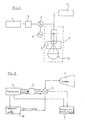
- a stabilised feeding unit (1) through a lowpass filter (2) and a square wave multiplier (3) or a wave multiplier of any suitable form (4), such as for instance: sinusoid, triangular, swath and so on, is connected, together with an analysis and processing circuit (7), to a lens antenna (5) having a generating cavity (8) containing the GUNN (9) diode feeding anode (19).
- the obstacle sensor is substantially constituted by an external envelope (10) in whose lower part there is provided a body (11) preferably from metal, provided with a regulation system that operates also as c polarisation circuit bearer (12). Body (11) has also a shield function against the intereferences due to the external magnetic fields.
- the seat (13) containing the generating diode (9) and anode (19) feeding the former, and wherein the generation cavity is configurated (8).
- Such containing seat (13) is also a cathode for the generating diode.
- the microwave generating GUNN diode is coupled to and fed by an anode connected to the feeding/receiving circuit.
- such anode may have solely the function of connecting GUNN diode (9) to feeding, or longitudinally develop above said diode for a length equal to 1 ⁇ 4 wave, and may be therefore protected and supported by an insulating core provided with the suitable electric connections necessary to the anode (19).
- Said core circumscribes in the upper part and coaxially the generating cavity (8); besides, it may comprise the necessary electric connections and possibly a partial metal covering for the connection with the underlying cylinder.
- the microwave generating GUNN diode (9), anode (19) and the frequency regulator (24) may be located in the cavity (8) generating the same waves emitted by said GUNN diode.
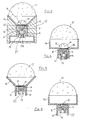
- the cavity may also be realised in a metal body or a seat (28) closed by a flange (26) having a suitable shape, in communication with the outside through an iris (27).
- an anti-dispersion empty space 25
- a device is located (6) for the automatic regulation of the temperature of antenna (5), as well as the necessary connection electronic components or electric elements.
- the temperature regulation system (6) may be of the retroactivated type or of the thermal drift electronic compensation type.
- the passive reflector is enclosed by a second external (17) from dielectric or artificial dielectric material, permeable to electromagnetic radiations and weathering-resistant, whose size is greater than the internal one (14).
- the obstacle sensor may be provided with several axially arranged lenses, or one only external lens (17).
- the antenna comprises at least one lens (17) from dielectric or artificial dielectric material, permeable to electromagnetic radiations and weathering-resistant, a polarisation apparatus (12), a microwave selection cavity (8), a system for regulating and keeping constant the temperature or of compensation of the thermal drift (6) and an external envelope (10), protected by a shock-proof layer (10') from rubber, shock-proof plastic material, or the like.
- the lens serves for the concentration of the electromagnetic waves emitted according to the main axis of the antenna (15).
- a reduction in the axial overall dimensions of the antenna may be obtained by adopting a lens having a short focal length, which may be realised as a stepped lens (20) which allows to reduce both the losses and the geometric proportions, with a reduction in its thickness.
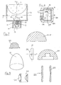
- the profile of the lens, or lenses affects the direction characteristics of the antenna (5), the width of the lobes of the radiation diagram being either equal or almost equal in all of the section planes, or very different in two orthogonal section planes.
- the lens only provide to the focusing of the beam in a plane, while, if necessary, a wave generation device provides to the beam generation in the second plane orthogonal to the first one.
- a lens having a hemispherical profile (14-17) irradiates in the xz plane in such a way that a spherical wave coming from its focus is converted into a wave having uniform phase fronts, while a lens having a differently shape profile, such as for instance a spherical sector lens with a cylindrical extension (29), causes the spherical wave, that has gone through the hemispherical lens, to have non uniform phase fronts.
- lenses may be realised that have different profiles in two section planes; a non limiting example may be that of the lens indicated by (30).
- the adopted lenses may be individual lenses having different configurations or coupled lenses having configurations either equal or different from one another.
- stepped or Fresnel lenses known to be little suitable for the practical use, as they have a very narrow band, may be exploited, in this specific case, in an optimum way as the transmission band iv very narrow in itself.
- types having openings of different shape, for instance rectangular or elliptic, may be used in the different embodiments, depending on the different focusing desired in the horizontal and the vertical planes.
- the lenses are used with different orientations: the hemispherical ones, with the meniscus oriented towards the outside or the inside of the antenna; the Fresnel ones, with the steps oriented towards the inside or the outside.
- the hemispherical ones with the meniscus oriented towards the outside or the inside of the antenna
- the Fresnel ones with the steps oriented towards the inside or the outside.
- no shadow zones appear which cause an increase in the secondary lobes of the radiation diagrams.
- dust and/or dirt accumulation in correspondence of the steps: this involves the need of utilising a further transparent protection permeable to electromagnetic radiation and resistant against weathering, located outside the system.
- optical apparatus is constituted at least by a lens
- the polarisation apparatus (12) allows only the passage of radiations having a specific polarisation, while it blocks those having an orthogonal polarisation as, in the very case of radars used for the remote sensing of vehicles, there might also be sensed, on the side of the main lobe or the secondary lobes of the radiation diagram, perturbing radiations ascribable to vehicles running laterally and frontally and in the contrary direction, and that use the same sensing system.
- the elimination of the perturbing radiations is solved in an optimum way by rotating the linear polarisation by 45°.
- the generation cavity may be for instance advantageously and economically obtained from aluminium, precision injection moulded parts or the like; it is substantially constituted by a metal body or seat (13) supported by the regulation and support body (11) or, in another solution, by a metal plate (26) and housing (28), in communication with the outside through a iris (27).
- Housing (28) contains the frequency selection apparatus (24), the GUNN diode feeding anode (19) and the same diode.
- the metal body or seat (13) as well as flange (26) and housing (28) may be obtained from steel or any other material suitable for the desired aim.
- the retroaction system of regulation of the temperature or of compensation of the thermal drift (6) has the function of keeping antenna (5) always at a constant temperature, or at least at a temperature comprised between specific prefixed boundaries.
- the external envelope (10) protects and insulates the system from the external environment; it is constituted by a housing, preferably from metal, produced by an injection moulding process or other adequate processes, and by a shock-proof envelope (10') preferably from rubber, shock-proof plastic material or the like.
- the electronic part is constituted by a stabilised feeding (1), a generator of square wave pulses or pulses of any other suitable form, such as for instance: sinusoid, triangular, saw-tooth, and so on, which generator acts as a modulator, and by a reception, processing and analysis circuit (7).
- the whole focal plane is rendered impermeable to electromagnetic waves by means of a metal surface, so that the frequencies higher or lower than the network frequency cannot reach the electronic circuit.
- the feeding, modulation, filtering, amplification and transception circuit, as well as the analysis circuit may also be of an integrated and miniaturised type.
Claims (18)
- Hindernissensor, der durch Kollimation und Fokussierung von emittierten Mikrowellen arbeitet, wobei der Hindemissensor umfasst:wobei die von der Antenne emittierten Mikrowellen durch die zumindest eine optische Vorrichtung in nur einem kohärenten und phasengleichen Strahl fokussiert und konzentriert werden und wobei in gleicher Richtung reflektierte Mikrowellen oder Echo, welche(s) auf der Erfassung eines Hindernisses beruhen (beruht) durch die Linsenantenne erfasst werden (wird);a) eine stabilisierte Zuführeinrichtung (1);b) eine Linsenantenne (5), die operativ an der stabilisierten Zuführeinrichtung (1) angeschlossen ist, Mikrowellen entlang einer Achse der Antenne emittiert und mit zumindest einer optischen Vorrichtung versehen ist, die zumindest eine fokussierende und konzentrierende Linse (14, 17) enthält;c) einen Analyse- und Arbeitsschaltkreis (7), der operativ an der stabilisierten Zuführeinrichtung (1) angeschlossen ist, undd) einen Wellenpulsgenerator (18), der operativ an der Zuführeinrichtung (1) und der Linsenantenne (5) angeschlossen ist,
dadurch gekennzeichnet, dass:die Linsenantenne eine äussere Umhüllung (10), einen Rumpf (11), der in der äusseren Umhüllung (10) vorgesehen ist, einen frequenzselektiven Erzeugungshohlraum (8), der eine Mikrowellenerzeugungsdiode (9) und eine Diodenzuführanode (19) aufnimmt, die in einem Sitz (13) angeordnet ist, der als Kathode für die Erzeugungsdiode (9) dient, die eine IMPATT- oder eine GUNN-Diode ist, enthält, wodurch der Erzeugungshohlraum (8), eine Polarisierungsvorrichtung (12), ein passiver Zwischenreflektor (15, 16) und von der zumindest einen Fokussierungs- und Konzentrationslinse eine erste Linse (17) in einer koaxialen Reihenfolge und entlang ihrer gemeinsamen Achse der Reihe nach vorgesehen sind; unddie reflektierten Mikrowellen oder das Echo, das auf der Erfassung eines Hindernisses beruht, durch die Mikrowellenerzeugungsdiode (9) analysiert und quantifiziert werden (wird). - Hindernissensor gemäss Anspruch 1, dadurch gekennzeichnet, dass die Mikrowellenerzeugungsdiode (9) eine IMPATT- Mikrowellenerzeugungsdiode ist.
- Hindernissensor gemäss Anspruch 1, dadurch gekennzeichnet, dass die Mikrowellenerzeugungsdiode (9) eine GUNN-Diode ist und die in gleicher Richtung reflektierten Mikrowellen oder das Echo dadurch in Abhängigkeit von dem Unterschied in der Frequenzverschiebung der GUMM-Diode als Energie- und Temperaturänderung analysiert und quantifiziert werden.
- Hindernissensor gemäss einem der vorhergehenden Ansprüche, dadurch gekennzeichnet, dass der Rumpf (11) und der Sitz (13) durch ein Gehäuse (28) gebildet sind, das durch einen Flansch (26) geschlossen ist und eine Frequenzauswahlvorrichtung (24), die Mikrowellenerzeugungsdiode (9) und die Anode (19), welche die Mikrowellenerzeugungsdiode (9) speist, beinhaltet, wobei das Gehäuse (28) den Hohlraum (8) bildet und durch eine Iris (27) nach aussen geöffnet ist.
- Hindernissensor gemäss einem der vorhergehenden Ansprüche, dadurch gekennzeichnet, dass ein Antidispersionsleerraum (25) zwischen dem Rumpf (11) und dem Sitz (13) vorgesehen ist, wobei eine Einrichtung (6) zur automatischen Temperaturregelung der Linsenantenne und optional elektrische und elektronische Verbindungselemente in dem Leerraum (25) angeordnet sind.
- Hindernissensor gemäss Anspruch 5, dadurch gekennzeichnet, dass die Einrichtung (6) zur automatischen Temperaturregelung von rückgekoppelter Art ist.
- Hindernissensor gemäss Anspruch 5, dadurch gekennzeichnet, dass die Einrichtung (6) zur automatischen Temperaturregelung von thermische Drift elektronisch kompensierender Art ist.
- Hindernissensor gemäss einem der vorhergehenden Ansprüche, dadurch gekennzeichnet, dass die Anode (19), welche die Mikrowellenerzeugungsdiode (9) speist, sich oberhalb der Diode (9) auf einer Länge gleich einer Viertelwelle longitudinal entwickelt und durch einen Isolierkern geschützt und getragen wird, der mit elektrischen Verbindungen für die Anode (19) versehen ist, wobei der Kern in dem oberen Teil und koaxial den Erzeugungshohlraum (8) begrenzt und die elektrischen Verbindungen umfasst.
- Hindernissensor gemäss einern der vorhergehenden Ansprüche, dadurch gekennzeichnet, dass eine zweite Linse (14), die aus dielektrischem Material hergestellt ist, für elektromagnetische Strahlung durchlässig und wetterbeständig ist, an der Basis des passiven Zwischenreflektors (15, 16) in dem oberen Abschnitt und koaxial zu dem Erzeugungshohlraum (8) angeordnet ist.
- Hindernissensor gemäss einem der vorhergehenden Ansprüche, dadurch gekennzeichnet, dass der passive Zwischenreflektor (16) eine zylindrische Form aufweist.
- Hindernissensor gemäss einem der vorhergehenden Ansprüche, dadurch gekennzeichnet, dass der passive Zwischenreflektor (15) eine abgeschnittene Konusform aufweist.
- Hindernissensor gemäss Anspruch 9, dadurch gekennzeichnet, dass die erste Linse (17) mit einer Grösse, die grösser als die der zweiten Linse (14) ist und aus dielektrischem Material hergestellt ist, das für elektromagnetische Strahlung durchlässig und wetterbeständig ist, an dem oberen Teil des passiven Zwischenreflektors (15, 16) angeordnet ist.
- Hindernissensor gemäss einem der vorhergehenden Ansprüche, dadurch gekennzeichnet, dass die äussere Umhüllung (10) durch eine stossfeste Schicht (10') bedeckt ist.
- Hindernissensor gemäss einem der vorhergehenden Ansprüche, dadurch gekennzeichnet, dass die erste Linse eine kleine Brennweite aufweist und von gestufter Art (20) ist.
- Hindernissensor, gemäss einem der vorhergehenden Ansprüche; dadurch gekennzeichnet, dass die Form der ersten Linse aus der Gruppe ausgewählt ist, die aus hemisphärischen, sphärischen, elliptischen, konkaven, konvexen, bikonvexen und Fresnellinsen besteht.
- Hindernissensor gemäss einem der vorhergehenden Ansprüche, dadurch gekennzeichnet, dass dieser erste und zweite Linsen mit unterschiedlicher Form enthält.
- Hindernissensor gemäss einem der vorhergehenden Ansprüche, dadurch gekennzeichnet, dass die äussere Umhüllung (10) und der Sitz (13) aus Aluminium hergestellt sind.
- Hindernissensor gemäss Anspruch 4, dadurch gekennzeichnet, dass der Sitz (13), das Gehäuse (28) und der Flansch (26) aus Stahl hergestellt sind.
Applications Claiming Priority (4)
| Application Number | Priority Date | Filing Date | Title |
|---|---|---|---|
| ITRE960089 | 1996-11-18 | ||
| IT96RE000089 IT1287826B1 (it) | 1996-11-18 | 1996-11-18 | Rilevatore d'ostacoli a concentrazione d'energia |
| IT97RE000080 IT1297992B1 (it) | 1997-10-28 | 1997-10-28 | Rilevatore di ostacoli a collimazione e focalizzazione dell'onda emessa |
| ITRE970080 | 1997-10-28 |
Publications (3)
| Publication Number | Publication Date |
|---|---|
| EP0843182A2 EP0843182A2 (de) | 1998-05-20 |
| EP0843182A3 EP0843182A3 (de) | 1999-05-26 |
| EP0843182B1 true EP0843182B1 (de) | 2003-10-22 |
Family
ID=26331979
Family Applications (1)
| Application Number | Title | Priority Date | Filing Date |
|---|---|---|---|
| EP97119777A Expired - Lifetime EP0843182B1 (de) | 1996-11-18 | 1997-11-12 | Hindernis-Sensor mit Kollimation und Fokussierung der emittierten Wellen |
Country Status (11)
| Country | Link |
|---|---|
| US (1) | US5991474A (de) |
| EP (1) | EP0843182B1 (de) |
| JP (1) | JPH10206536A (de) |
| KR (1) | KR19980042409A (de) |
| CN (1) | CN1118711C (de) |
| AR (1) | AR010613A1 (de) |
| AT (1) | ATE252735T1 (de) |
| BR (1) | BR9705387A (de) |
| DE (1) | DE69725679T2 (de) |
| ES (1) | ES2208805T3 (de) |
| PL (1) | PL323217A1 (de) |
Cited By (2)
| Publication number | Priority date | Publication date | Assignee | Title |
|---|---|---|---|---|
| DE102004044073A1 (de) * | 2004-09-11 | 2006-03-16 | Volkswagen Ag | Vorrichtung und Verfahren zur automatischen Geschwindigkeits- und/oder Abstandsregelung für ein Fahrzeug |
| DE102009042285A1 (de) | 2009-09-22 | 2011-03-31 | Volkswagen Ag | Schirmung von Radarsensorik |
Families Citing this family (19)
| Publication number | Priority date | Publication date | Assignee | Title |
|---|---|---|---|---|
| EP0978729A3 (de) * | 1998-08-07 | 2002-03-20 | Hitachi, Ltd. | Hochfrequenz-Sende-Empfangsvorrichtung für Fahrzeug-Radarsysteme |
| JP2002257932A (ja) * | 2001-03-06 | 2002-09-11 | Nippon Telegr & Teleph Corp <Ntt> | 反射電磁波検出型イメージング装置 |
| US7456803B1 (en) * | 2003-05-12 | 2008-11-25 | Hrl Laboratories, Llc | Large aperture rectenna based on planar lens structures |
| DE102004063574A1 (de) * | 2004-12-30 | 2006-07-13 | Osram Opto Semiconductors Gmbh | Leuchtvorrichtung mit mehreren Halbleiterlichtquellen |
| ITRE20060152A1 (it) | 2006-12-15 | 2008-06-16 | Franco Baldi | Perfezionamenti a rilevatore di ostacoli a collimazione e focalizzazione dell'onda emessa. |
| DE102007036262A1 (de) * | 2007-08-02 | 2009-02-05 | Robert Bosch Gmbh | Radarsensor für Kraftfahrzeuge |
| US8797207B2 (en) * | 2011-04-18 | 2014-08-05 | Vega Grieshaber Kg | Filling level measuring device antenna cover |
| ITMI20111643A1 (it) | 2011-09-13 | 2013-03-14 | Franco Baldi | Generatore lenticolare di corrente elettrica a concentrazione di fotoni con reazione termica ibrido e compatto a differenti focalizzazioni della luce visibile e invisibile |
| DE102012202913A1 (de) * | 2012-02-27 | 2013-08-29 | Robert Bosch Gmbh | Radarsensor |
| ES2435797B1 (es) * | 2012-05-30 | 2015-04-06 | Electrónica Falcón, S.A. | Equipo de seguridad de caza, y procedimiento de funcionamiento de dicho equipo |
| US9293815B1 (en) | 2013-09-24 | 2016-03-22 | The United States Of America As Represented By The Secretary Of The Navy | Ultra-wideband hemispherical teardrop antenna with a conical ground |
| ES2546784B1 (es) * | 2014-03-28 | 2016-07-04 | Adartia Servicios, S.L. | Dispositivo amplificador para antenas de radar |
| JP6298715B2 (ja) * | 2014-05-30 | 2018-03-20 | 日立オートモティブシステムズ株式会社 | アンテナ装置およびそれを用いた速度センサ |
| US10215852B1 (en) | 2015-10-05 | 2019-02-26 | Google Llc | Robotic radar assistance |
| DE102015015034B4 (de) * | 2015-11-23 | 2023-04-27 | Baumer Electric Ag | Sensoranordnung |
| JP2018198380A (ja) * | 2017-05-24 | 2018-12-13 | 新日本無線株式会社 | アンテナ装置 |
| EP3534173B1 (de) * | 2018-02-28 | 2023-08-02 | Baumer Electric AG | Gehäuseanordnung für einen radarsensor |
| CN111429623A (zh) * | 2020-05-12 | 2020-07-17 | 贵州国卫信安科技有限公司 | 一种防止无线钥匙信号被破解干扰的系统及其使用方法 |
| CN113050038A (zh) * | 2021-03-23 | 2021-06-29 | 上海交通大学 | 一种基于虚拟阵列扩展的变电站声源定位方法及系统 |
Family Cites Families (7)
| Publication number | Priority date | Publication date | Assignee | Title |
|---|---|---|---|---|
| US4517566A (en) * | 1982-09-07 | 1985-05-14 | John H. Bryant | True ground speed sensor |
| US5202692A (en) * | 1986-06-16 | 1993-04-13 | Millitech Corporation | Millimeter wave imaging sensors, sources and systems |
| US4845422A (en) * | 1986-12-24 | 1989-07-04 | General Electric Company | Microwave proximity sensor |
| US5227800A (en) * | 1988-04-19 | 1993-07-13 | Millitech Corporation | Contraband detection system |
| FR2669115B1 (fr) * | 1990-11-09 | 1993-04-23 | Thomson Csf | Systeme radar en ondes millimetriques pour le guidage d'un robot mobile au sol. |
| US5455589A (en) * | 1994-01-07 | 1995-10-03 | Millitech Corporation | Compact microwave and millimeter wave radar |
| DE4412770A1 (de) * | 1994-04-13 | 1995-10-19 | Siemens Ag | Mikrowellen-Linsenantennenanordnung für Kraftfahrzeug-Abstandswarnradar |
-
1997
- 1997-11-12 EP EP97119777A patent/EP0843182B1/de not_active Expired - Lifetime
- 1997-11-12 AT AT97119777T patent/ATE252735T1/de not_active IP Right Cessation
- 1997-11-12 DE DE69725679T patent/DE69725679T2/de not_active Expired - Lifetime
- 1997-11-12 ES ES97119777T patent/ES2208805T3/es not_active Expired - Lifetime
- 1997-11-13 US US08/970,074 patent/US5991474A/en not_active Expired - Lifetime
- 1997-11-14 KR KR1019970059899A patent/KR19980042409A/ko not_active Application Discontinuation
- 1997-11-17 JP JP9315190A patent/JPH10206536A/ja active Pending
- 1997-11-17 BR BR9705387A patent/BR9705387A/pt not_active Application Discontinuation
- 1997-11-17 AR ARP970105364A patent/AR010613A1/es unknown
- 1997-11-18 CN CN97120178A patent/CN1118711C/zh not_active Expired - Fee Related
- 1997-11-18 PL PL97323217A patent/PL323217A1/xx unknown
Cited By (3)
| Publication number | Priority date | Publication date | Assignee | Title |
|---|---|---|---|---|
| DE102004044073A1 (de) * | 2004-09-11 | 2006-03-16 | Volkswagen Ag | Vorrichtung und Verfahren zur automatischen Geschwindigkeits- und/oder Abstandsregelung für ein Fahrzeug |
| DE102009042285A1 (de) | 2009-09-22 | 2011-03-31 | Volkswagen Ag | Schirmung von Radarsensorik |
| DE102009042285B4 (de) | 2009-09-22 | 2023-05-17 | Volkswagen Ag | Schirmung von Radarsensorik |
Also Published As
| Publication number | Publication date |
|---|---|
| JPH10206536A (ja) | 1998-08-07 |
| CN1118711C (zh) | 2003-08-20 |
| DE69725679T2 (de) | 2004-07-29 |
| US5991474A (en) | 1999-11-23 |
| AR010613A1 (es) | 2000-06-28 |
| DE69725679D1 (de) | 2003-11-27 |
| KR19980042409A (ko) | 1998-08-17 |
| EP0843182A2 (de) | 1998-05-20 |
| ATE252735T1 (de) | 2003-11-15 |
| BR9705387A (pt) | 1999-06-29 |
| CN1186245A (zh) | 1998-07-01 |
| ES2208805T3 (es) | 2004-06-16 |
| EP0843182A3 (de) | 1999-05-26 |
| PL323217A1 (en) | 1998-05-25 |
Similar Documents
| Publication | Publication Date | Title |
|---|---|---|
| EP0843182B1 (de) | Hindernis-Sensor mit Kollimation und Fokussierung der emittierten Wellen | |
| JP2670422B2 (ja) | ミリ波レーダセンサのための組付け放射構造体 | |
| US7408500B2 (en) | Automotive radar | |
| JP2690271B2 (ja) | 3次元画像ミリメートル波の追跡および誘導システム | |
| JP3302849B2 (ja) | 車載用レーダーモジュール | |
| EP1416292B1 (de) | Geschwenktes optisches Radar System | |
| US11509045B2 (en) | Vehicle body part comprising at least one directional antenna | |
| EP0498524A2 (de) | Detektorsystem | |
| US20120133547A1 (en) | Automotive Radar System and Method for Using Same | |
| US6057797A (en) | Radar sensor for use in motor vehicles | |
| CA2166110A1 (en) | Radiation sensor | |
| US20210296764A1 (en) | Continuously steering phased array and headlight radars | |
| Vizard et al. | Antenna range evaluations of low THz imagers for automotive applications | |
| WO2003016943A1 (en) | Near object detection system | |
| WO2000079647A1 (en) | Steerable transponders | |
| Najm | Comparison of alternative crash-avoidance sensor technologies | |
| JP2626839B2 (ja) | 車載レーダ装置 | |
| RU2790456C2 (ru) | Элемент кузова транспортного средства, содержащий по меньшей мере одну направленную антенну | |
| Hani | LiDAR vs RADAR: Detection, Tracking, and Imaging | |
| ITRE970080A1 (it) | Rilevatore di ostacoli a collimazione e focalizzazione dell'onda emess a | |
| Lowbridge | Low-cost mm-wave radar for cruise control | |
| CN2106756U (zh) | 车辆防撞、或报警自动检测器 | |
| Pergande et al. | Passive millimeter wave imaging | |
| CN117538862A (zh) | 一种弯曲道路上基于智能超表面的非视距目标检测方法 | |
| Compans et al. | MM-wave radar sensor with proven capabilities of enhanced vision |
Legal Events
| Date | Code | Title | Description |
|---|---|---|---|
| PUAI | Public reference made under article 153(3) epc to a published international application that has entered the european phase |
Free format text: ORIGINAL CODE: 0009012 |
|
| AK | Designated contracting states |
Kind code of ref document: A2 Designated state(s): AT BE CH DE DK ES FI FR GB GR IE LI LU MC NL PT SE |
|
| AX | Request for extension of the european patent |
Free format text: AL;LT;LV;RO;SI |
|
| PUAL | Search report despatched |
Free format text: ORIGINAL CODE: 0009013 |
|
| AK | Designated contracting states |
Kind code of ref document: A3 Designated state(s): AT BE CH DE DK ES FI FR GB GR IE IT LI LU MC NL PT SE |
|
| AX | Request for extension of the european patent |
Free format text: AL;LT;LV;RO;SI |
|
| 17P | Request for examination filed |
Effective date: 19991007 |
|
| AKX | Designation fees paid |
Free format text: AT BE CH DE DK ES FI FR GB GR IE LI LU MC NL PT SE |
|
| 17Q | First examination report despatched |
Effective date: 20020729 |
|
| GRAH | Despatch of communication of intention to grant a patent |
Free format text: ORIGINAL CODE: EPIDOS IGRA |
|
| GRAS | Grant fee paid |
Free format text: ORIGINAL CODE: EPIDOSNIGR3 |
|
| GRAA | (expected) grant |
Free format text: ORIGINAL CODE: 0009210 |
|
| AK | Designated contracting states |
Kind code of ref document: B1 Designated state(s): AT BE CH DE DK ES FI FR GB GR IE LI LU MC NL PT SE |
|
| PG25 | Lapsed in a contracting state [announced via postgrant information from national office to epo] |
Ref country code: NL Free format text: LAPSE BECAUSE OF FAILURE TO SUBMIT A TRANSLATION OF THE DESCRIPTION OR TO PAY THE FEE WITHIN THE PRESCRIBED TIME-LIMIT Effective date: 20031022 Ref country code: FI Free format text: LAPSE BECAUSE OF FAILURE TO SUBMIT A TRANSLATION OF THE DESCRIPTION OR TO PAY THE FEE WITHIN THE PRESCRIBED TIME-LIMIT Effective date: 20031022 Ref country code: BE Free format text: LAPSE BECAUSE OF FAILURE TO SUBMIT A TRANSLATION OF THE DESCRIPTION OR TO PAY THE FEE WITHIN THE PRESCRIBED TIME-LIMIT Effective date: 20031022 Ref country code: AT Free format text: LAPSE BECAUSE OF FAILURE TO SUBMIT A TRANSLATION OF THE DESCRIPTION OR TO PAY THE FEE WITHIN THE PRESCRIBED TIME-LIMIT Effective date: 20031022 |
|
| REG | Reference to a national code |
Ref country code: GB Ref legal event code: FG4D |
|
| REG | Reference to a national code |
Ref country code: CH Ref legal event code: EP |
|
| PG25 | Lapsed in a contracting state [announced via postgrant information from national office to epo] |
Ref country code: LU Free format text: LAPSE BECAUSE OF NON-PAYMENT OF DUE FEES Effective date: 20031112 Ref country code: IE Free format text: LAPSE BECAUSE OF NON-PAYMENT OF DUE FEES Effective date: 20031112 |
|
| REG | Reference to a national code |
Ref country code: IE Ref legal event code: FG4D |
|
| REF | Corresponds to: |
Ref document number: 69725679 Country of ref document: DE Date of ref document: 20031127 Kind code of ref document: P |
|
| PG25 | Lapsed in a contracting state [announced via postgrant information from national office to epo] |
Ref country code: MC Free format text: LAPSE BECAUSE OF NON-PAYMENT OF DUE FEES Effective date: 20031130 |
|
| PG25 | Lapsed in a contracting state [announced via postgrant information from national office to epo] |
Ref country code: GR Free format text: LAPSE BECAUSE OF FAILURE TO SUBMIT A TRANSLATION OF THE DESCRIPTION OR TO PAY THE FEE WITHIN THE PRESCRIBED TIME-LIMIT Effective date: 20040122 Ref country code: DK Free format text: LAPSE BECAUSE OF FAILURE TO SUBMIT A TRANSLATION OF THE DESCRIPTION OR TO PAY THE FEE WITHIN THE PRESCRIBED TIME-LIMIT Effective date: 20040122 |
|
| REG | Reference to a national code |
Ref country code: SE Ref legal event code: TRGR |
|
| NLV1 | Nl: lapsed or annulled due to failure to fulfill the requirements of art. 29p and 29m of the patents act | ||
| REG | Reference to a national code |
Ref country code: CH Ref legal event code: PL |
|
| REG | Reference to a national code |
Ref country code: CH Ref legal event code: AEN Free format text: PROSEGUIMENTO DELLA PROCEDURA APPROVATO |
|
| REG | Reference to a national code |
Ref country code: CH Ref legal event code: PK Free format text: PROSEGUIMENTO DELLA PROCEDURA APPROVATO. |
|
| REG | Reference to a national code |
Ref country code: ES Ref legal event code: FG2A Ref document number: 2208805 Country of ref document: ES Kind code of ref document: T3 |
|
| ET | Fr: translation filed | ||
| REG | Reference to a national code |
Ref country code: IE Ref legal event code: MM4A |
|
| PLBE | No opposition filed within time limit |
Free format text: ORIGINAL CODE: 0009261 |
|
| STAA | Information on the status of an ep patent application or granted ep patent |
Free format text: STATUS: NO OPPOSITION FILED WITHIN TIME LIMIT |
|
| 26N | No opposition filed |
Effective date: 20040723 |
|
| PG25 | Lapsed in a contracting state [announced via postgrant information from national office to epo] |
Ref country code: PT Free format text: LAPSE BECAUSE OF NON-PAYMENT OF DUE FEES Effective date: 20040322 |
|
| PGFP | Annual fee paid to national office [announced via postgrant information from national office to epo] |
Ref country code: GB Payment date: 20101117 Year of fee payment: 14 |
|
| PGFP | Annual fee paid to national office [announced via postgrant information from national office to epo] |
Ref country code: SE Payment date: 20111122 Year of fee payment: 15 Ref country code: FR Payment date: 20111115 Year of fee payment: 15 Ref country code: ES Payment date: 20111123 Year of fee payment: 15 |
|
| PGFP | Annual fee paid to national office [announced via postgrant information from national office to epo] |
Ref country code: DE Payment date: 20111213 Year of fee payment: 15 |
|
| PGFP | Annual fee paid to national office [announced via postgrant information from national office to epo] |
Ref country code: CH Payment date: 20120525 Year of fee payment: 15 |
|
| REG | Reference to a national code |
Ref country code: CH Ref legal event code: PL |
|
| GBPC | Gb: european patent ceased through non-payment of renewal fee |
Effective date: 20121112 |
|
| PG25 | Lapsed in a contracting state [announced via postgrant information from national office to epo] |
Ref country code: CH Free format text: LAPSE BECAUSE OF FAILURE TO SUBMIT A TRANSLATION OF THE DESCRIPTION OR TO PAY THE FEE WITHIN THE PRESCRIBED TIME-LIMIT Effective date: 20121130 Ref country code: SE Free format text: LAPSE BECAUSE OF NON-PAYMENT OF DUE FEES Effective date: 20121113 Ref country code: LI Free format text: LAPSE BECAUSE OF FAILURE TO SUBMIT A TRANSLATION OF THE DESCRIPTION OR TO PAY THE FEE WITHIN THE PRESCRIBED TIME-LIMIT Effective date: 20121130 |
|
| REG | Reference to a national code |
Ref country code: FR Ref legal event code: ST Effective date: 20130731 |
|
| REG | Reference to a national code |
Ref country code: DE Ref legal event code: R119 Ref document number: 69725679 Country of ref document: DE Effective date: 20130601 |
|
| PG25 | Lapsed in a contracting state [announced via postgrant information from national office to epo] |
Ref country code: DE Free format text: LAPSE BECAUSE OF NON-PAYMENT OF DUE FEES Effective date: 20130601 |
|
| PG25 | Lapsed in a contracting state [announced via postgrant information from national office to epo] |
Ref country code: GB Free format text: LAPSE BECAUSE OF NON-PAYMENT OF DUE FEES Effective date: 20121112 Ref country code: FR Free format text: LAPSE BECAUSE OF NON-PAYMENT OF DUE FEES Effective date: 20121130 |
|
| REG | Reference to a national code |
Ref country code: ES Ref legal event code: FD2A Effective date: 20140304 |
|
| PG25 | Lapsed in a contracting state [announced via postgrant information from national office to epo] |
Ref country code: ES Free format text: LAPSE BECAUSE OF NON-PAYMENT OF DUE FEES Effective date: 20121113 |