EP0843161B1 - Flaschenaufsatzdispenser - Google Patents
Flaschenaufsatzdispenser Download PDFInfo
- Publication number
- EP0843161B1 EP0843161B1 EP97119508A EP97119508A EP0843161B1 EP 0843161 B1 EP0843161 B1 EP 0843161B1 EP 97119508 A EP97119508 A EP 97119508A EP 97119508 A EP97119508 A EP 97119508A EP 0843161 B1 EP0843161 B1 EP 0843161B1
- Authority
- EP
- European Patent Office
- Prior art keywords
- limiter
- volume
- bottle cap
- volume indicator
- cap according
- Prior art date
- Legal status (The legal status is an assumption and is not a legal conclusion. Google has not performed a legal analysis and makes no representation as to the accuracy of the status listed.)
- Expired - Lifetime
Links
Images
Classifications
-
- G—PHYSICS
- G01—MEASURING; TESTING
- G01F—MEASURING VOLUME, VOLUME FLOW, MASS FLOW OR LIQUID LEVEL; METERING BY VOLUME
- G01F15/00—Details of, or accessories for, apparatus of groups G01F1/00 - G01F13/00 insofar as such details or appliances are not adapted to particular types of such apparatus
- G01F15/007—Details of, or accessories for, apparatus of groups G01F1/00 - G01F13/00 insofar as such details or appliances are not adapted to particular types of such apparatus comprising means to prevent fraud
-
- G—PHYSICS
- G01—MEASURING; TESTING
- G01F—MEASURING VOLUME, VOLUME FLOW, MASS FLOW OR LIQUID LEVEL; METERING BY VOLUME
- G01F11/00—Apparatus requiring external operation adapted at each repeated and identical operation to measure and separate a predetermined volume of fluid or fluent solid material from a supply or container, without regard to weight, and to deliver it
- G01F11/02—Apparatus requiring external operation adapted at each repeated and identical operation to measure and separate a predetermined volume of fluid or fluent solid material from a supply or container, without regard to weight, and to deliver it with measuring chambers which expand or contract during measurement
- G01F11/021—Apparatus requiring external operation adapted at each repeated and identical operation to measure and separate a predetermined volume of fluid or fluent solid material from a supply or container, without regard to weight, and to deliver it with measuring chambers which expand or contract during measurement of the piston type
- G01F11/023—Apparatus requiring external operation adapted at each repeated and identical operation to measure and separate a predetermined volume of fluid or fluent solid material from a supply or container, without regard to weight, and to deliver it with measuring chambers which expand or contract during measurement of the piston type with provision for varying the stroke of the piston
-
- G—PHYSICS
- G01—MEASURING; TESTING
- G01F—MEASURING VOLUME, VOLUME FLOW, MASS FLOW OR LIQUID LEVEL; METERING BY VOLUME
- G01F11/00—Apparatus requiring external operation adapted at each repeated and identical operation to measure and separate a predetermined volume of fluid or fluent solid material from a supply or container, without regard to weight, and to deliver it
- G01F11/02—Apparatus requiring external operation adapted at each repeated and identical operation to measure and separate a predetermined volume of fluid or fluent solid material from a supply or container, without regard to weight, and to deliver it with measuring chambers which expand or contract during measurement
- G01F11/021—Apparatus requiring external operation adapted at each repeated and identical operation to measure and separate a predetermined volume of fluid or fluent solid material from a supply or container, without regard to weight, and to deliver it with measuring chambers which expand or contract during measurement of the piston type
- G01F11/025—Apparatus requiring external operation adapted at each repeated and identical operation to measure and separate a predetermined volume of fluid or fluent solid material from a supply or container, without regard to weight, and to deliver it with measuring chambers which expand or contract during measurement of the piston type with manually operated pistons
- G01F11/028—Apparatus requiring external operation adapted at each repeated and identical operation to measure and separate a predetermined volume of fluid or fluent solid material from a supply or container, without regard to weight, and to deliver it with measuring chambers which expand or contract during measurement of the piston type with manually operated pistons the dosing device being provided with a dip tube and fitted to a container, e.g. to a bottleneck
-
- G—PHYSICS
- G01—MEASURING; TESTING
- G01F—MEASURING VOLUME, VOLUME FLOW, MASS FLOW OR LIQUID LEVEL; METERING BY VOLUME
- G01F25/00—Testing or calibration of apparatus for measuring volume, volume flow or liquid level or for metering by volume
- G01F25/10—Testing or calibration of apparatus for measuring volume, volume flow or liquid level or for metering by volume of flowmeters
Definitions
- the invention relates to a bottle top dispenser with a digital volume display with the features of the preamble of claim 1.
- the known bottle-top dispenser from which the invention proceeds (US 4,159,784 A) has for digital volume display a mechanical counter, the with a serving as a limiter of the piston-cylinder stroke adjustment stop connected via a mechanical transmission.
- the transmission connection is rigid. Therefore, it is not possible for the user to adjust the dispenser. to the displayed and actually dispensed volume of liquid in To bring agreement.
- a zero point adjustment of the limiter which in turn has a fixed stop and an adjustment stop, provided by the fact that the position of the fixed stop by means of a calibration screw can be changed slightly and permanently. At the fixed gear connection the volume display with the adjustment stop of the limiter nothing changes.
- a bottle top dispenser (US 4,074,831 A), in which the Adjustment stop is connected to the piston by means of a rack. Of the Adjustment stop can thus be adjusted in stages. A zero point adjustment takes place here by an adjusting screw, which is assigned to the cylinder fixed counter-stop is arranged and the attachment point of the adjustment stop allowed to change the piston minimally.
- the teaching is based on the problem, the above-mentioned bottle top dispenser with digital volume display in such a way that the displayed and the actual volume dispensed by adjustment in accordance can be brought.
- limiter should not be limited to an adjustment stop, mind you but denote any functional element that has the maximum axial input and Ausfahrhubrange of the piston and cylinder relative to each other limited in one direction or another direction or both directions.
- the limiter is therefore a Hubumblenbegrenzer.
- the limiter acts mechanically.
- the volume display is mechanical. Between limiter and volume indicator There is a mechanical transmission connection, which is used for adjustment decouple and reconnect.
- the limiter for the maximum stroke of the piston and cylinder can also electrically, electronically, optically or acoustically and his attitude detected electrically, electronically, optically or acoustically and digitally displayed become.
- the adjustment in an independent state of Limiter and digital volume display is accordingly also electrical, electronic, to understand visually or acoustically.
- the case is included here be an electronic volume indicator on the actually issued Volume readjust by the display value by data entry z. B. is changed via a keyboard, without it being a mechanical decoupling limiter and volume display would be needed as these are not mechanically coupled are.
- the limiter preferably has a first one Stop, which limits the piston-cylinder stroke when sucking, and a second stop, which limits the piston-cylinder stroke when dispensing.
- a first one Stop which limits the piston-cylinder stroke when sucking
- a second stop which limits the piston-cylinder stroke when dispensing.
- For adjustment can be in the decoupled state of limiter and volume display the first stop or the second stop or the volume indicator can be adjusted.
- one of the stops an adjustment stop for volume adjustment.
- For adjustment is in the decoupled state of limiter and volume display held the adjustable stop and adjusted the volume display. This is especially handy as the user actually does Measure output volumes and in just one step can adjust the volume display accordingly.
- Holding the adjustable stop ensures that at the setting when adjusting nothing changes. It will So only the volume display to the actually issued Volume adjusted.
- the dispenser for Volume adjustment a knob on which a sprocket arranged is.
- the volume indicator is behind one Close, which must be opened for adjustment.
- opening the clasp drives a nose or the like into the ring gear of the knob to block it.
- the volume display is performed by means of a counter whose counter shaft via a bevel gear is coupled to a threaded spindle, the one of the limiter setting is subject to proportional rotation.
- the counter shaft is a detachable spacer blocked in engagement position of the bevel gears. She lets after disengaging the spacer disengaged from the bevel gears back and turn on a knob.
- the dispenser has a Seal up, which will be broken when first adjusting.
- the breaking of the seal should be a striking mark in the Volume display panel of the dispenser will be visible to the user to signal that the volume indication from the manufacturer Basic adjustment, for which there is a certificate of conformity gives. This is among other things for possible warranty claims significant.
- the spacer is secured with a plastic strip when first loosening of the spacer is torn off and the marking visible can be.
- the plastic strip is located in the volume display field in front of the spacer, so he covers this up. After tearing off the plastic strip The spacer itself is visible as a marker. To achieve the desired signal effect, there is the Distanx piece preferably made of a material whose color is clear from that of the volume display panel and plastic strip different.
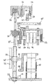
- the bottle top dispenser has a cylinder 10 and a therein axially displaceably arranged piston 12.
- extending of the piston 12 from the cylinder 10 is liquid from a Bottle, on which the dispenser sits, sucked into the cylinder 10.
- retracting the piston 12 into the cylinder 10 is Liquid from the cylinder 10 transported to an outlet and spent. The piston movement is done by hand. It is given a certain stroke of the piston 12, the desired output volume of liquid corresponds.
- the stroke of the piston 12 is limited by stops 14, 16, with a fixed to the piston 12 counter-stop 18 cooperate.
- the retraction of the piston 12 in the Cylinder 10 for the purpose of dispensing liquid limiting stop 14 is a fixed stop connected to the cylinder 10 14.
- the extension of the piston 12 from the cylinder 10 in order Suction of liquid limiting stop 16 is a Verstellanschlag, for its adjustment and thus adjustment the output volume, a threaded spindle 20 is used.
- the threaded spindle 20 extends parallel to the cylinder axis. It is in axially fixed position with respect to the cylinder 10 rotatably mounted 22.
- the threaded spindle 20 has an external thread.
- the adjustment stop 16 is provided with a threaded bushing 26, which has a matching internal thread, on the threaded spindle 20 screwed and twist-30 guided 32. The adjustment stop 16 is axially adjusted by turning the threaded spindle 20.
- the knob 34 For rotating the threaded spindle 20 and thus adjusting the output volume serves a knob 34 at the upper end of the threaded spindle 20.
- the knob 34 has a cylindrical pot shape with opening down. He is around a central cylinder axis 36 rotatably mounted and has on its inner shell an axial Gearing 38, with a corresponding axial toothing 40 at the upper end of the threaded spindle 20 meshes.
- the hand-operated Rotation of the knob 34 is in a rapid rotation of Threaded spindle 20 translated.
- the dispenser has a digital volume display by means of a Counter 42, via a gear to the threaded spindle 20th is coupled.
- the gearbox is a bevel gearbox.
- a first bevel gear 44 On the threaded spindle 20 is rigidly seated a first bevel gear 44, and on the counter shaft 46 rigidly a second bevel gear 48, between which a normally rigid torque transmitting Connection exists. If the knob 34 is rotated and the adjustment stop 16 and thus the dispensing volume of the dispenser adjusted, there is a proportional adjustment of the Counter 42 for displaying the output volume.
- the dispenser has a basic adjustment by the manufacturer the volume of fluid displayed and actually dispensed for deionized water under normal conditions. There is a certificate of conformity of the Manufacturer.
- the knob 34 has at the bottom of the inner shell a sprocket 52, and the slider 50 a nose 54 which enters the sprocket 52 and thereby blocked the knob 34. It is so certain that the Knob 34 and the adjustment stop 16 during the adjustment process no position change experienced.
- a spacer 56 When the slide 50 is open, a spacer 56 is accessible, that engages the bevel gear 48 on the counter shaft 46 blocked with the bevel gear 44 on the threaded spindle 20.
- the spacer 56 is made of colored plastic. It lies behind a plastic strip serving as a seal 58, on one of the bearing blocks 64 for the counter shaft 46th is attached and the spacer 56 hidden.
- the plastic strip 58 takes a spacer 56 concealing Position behind a window 60, through which the Volume display of the counter 42 is visible.
- the first removal of the spacer 56 from the counter shaft 46 is the plastic strip 58 demolished and the colored spacer 56 visible through the window 60.
Landscapes
- Physics & Mathematics (AREA)
- Fluid Mechanics (AREA)
- General Physics & Mathematics (AREA)
- Containers And Packaging Bodies Having A Special Means To Remove Contents (AREA)
Description
- 10
- Zylinder
- 12
- Kolben
- 14
- Festanschlag
- 16
- Verstellanschlag
- 18
- Gegenanschlag
- 20
- Gewindespindel
- 22
- Lager
- 26
- Gewindebuchse
- 30
- Verdrehsicherung
- 32
- Führung
- 34
- Drehknopf
- 36
- Zylinderachse
- 38
- Verzahnung
- 40
- Verzahnung
- 42
- Zählwerk
- 44
- Kegelzahnrad
- 46
- Zählwerkswelle
- 48
- Kegelzahnrad
- 50
- Schieber
- 52
- Zahnkranz
- 54
- Nase
- 56
- Distanzstück
- 58
- Kunststoffstreifen
- 60
- Fenster
- 62
- Stellknopf
- 64
- Lagerbock
Claims (10)
- Flaschenaufsatzdispenser mit einer Kolben-Zylinder-Einheit, deren Kolben (12) und Zylinder (10) in einer axialen Hubbewegung relativ zueinander betätigbar sind, um Flüssigkeit aus einer Flasche, auf der der Dispenser sitzt, anzusaugen und auszugeben, mit einem einstellbaren Begrenzer für den maximalen Hub von Kolben (12) und Zylinder (10) relativ zueinander, mit einem Stellelement (34) zum Ändern der Begrenzereinstellung und mit einer digitalen Volumenanzeige (42), die bei Änderung der Begrenzereinstellung selbsttätig proportional dazu mit geändert wird,
dadurch gekennzeichnet, daß Begrenzer (14, 16) und Volumenanzeige (42) voneinander entkoppelbar sind und daß die Volumenanzeige (42) in ihrem von dem Begrenzer (14, 16) entkoppelten Zustand veränderbar ist, ohne daß sich die Begrenzereinstellung ändert, um so das angezeigte und das tatsächlich ausgegebene Volumen in Übereinstimmung zu bringen. - Flaschenaufsatzdispenser nach Anspruch 1, dadurch gekenntzeichnet, daß die Volumenanzeige (42) in ihrem von dem Begrenzer (14, 16) entkoppelten Zustand electronisch per Dateneingabe veränderbar ist.
- Flaschenaufsatzdispenser nach Anspruch 1 oder 2, dadurch gekennzeichnet, daß der Begrenzer (14, 16) mechanisch wirkt, daß die Volumenanzeige(42) mechanisch erfolgt, und daß zwischen Begrenzer (14, 16) und Volumenanzeige(42) eine entkoppelbare und wieder koppelbare mechanische Getriebeverbindung (44, 4b, 48) besteht.
- Flaschenaufsatzdispenser nach einem der Anspruche 1 bis 3, dadurch gekennzeichnet, daß der Begrenzer (14, 16) einen Verstellanschlag (16) zur Volumenverstellung aufweist und daß zur Justierung im entkoppelten Zustand von Begrenzer (14, 16) und Volumenanzeige (42) der Verstellanschlag (16) festgehalten wird, während die Volumenanzeige (42) unabhängig verstellbar ist.
- Flaschenaufsatzdispenser nach Anspruch 4, dadurch gekennzeichnet, daß zur Volumenverstellung ein Drehknopf (34) vorgesehen ist, an dem ein Zahnkranz (52) angeordnet ist, daß sich die Volumenanzeige (42) hinter einer Schließe (50) befindet, die zur Justierung geöffnet werden muß, und daß beim Öffnen der Schließe (50) eine daran sitzende Nase (54) o. ä. in den Zahnkranz (52) einfährt und den Drehknopf (34) blockiert.
- Flaschenaufsatzdispenser nach Anspruch 3 und ggf. Anspruch 4 oder 5, dadurch gekennzeichnet, daß die Volumenanzeige (42) als Zählwerk ausgeführt ist, dessen Zählwerkswelle (46) über ein Kegelzahnradgetriebe (44, 48) an eine Gewindespindel (20) angekoppelt ist, die einer der Begrenzereinstellung proportionalen Drehung unterliegt, und daß die Zählwerkswelle (46) durch ein lösbares Distanzstück (56) in Eingriffsstellung das Kegelzahnrad (44, 48) blockiert und nach Lösen des Distanzstücks (56) außer Eingriff der Kegelzahnräder (44, 48) rückbar und an einem Stellknopf (62) drehbar ist.
- Flaschenaufsatzdispenser nach einem der Ansprüche 1 bis 6, dadurch gekennzeichnet, daß eine Plombe (58) vorgesehen ist, die beim ersten Justieren gebrochen wird.
- Flaschenaufsatzdispenser nach Anspruch 7, dadurch gekennzeichnet, daß nach dem Brechen der Plombe (58) eine auffällige Markierung in der Volumenanzeige (42) sichtbar wird.
- Flaschenaufsatzdispenser nach den Ansprüchen 6 bis 8, dadurch gekennzeichnet, daß das Distanzstück (56) mit einem Kunststoffstreifen (58) gesichert ist, der beim ersten Lösen des Distanzstücks (56) abgerissen wird und die Markierung sichtbar werden läßt.
- Flaschenaufsatzdispenser nach Anspruch 9, dadurch gekennzeichnet, daß sich der Kunststoffstreifen (58) in der Volumenanzeige (42) vor dem Distanzstück (56) befindet und dieses verdeckt und nach dem Abreißen das Distanzstück (56) selbst als Markierung sichtbar werden läßt.
Applications Claiming Priority (2)
| Application Number | Priority Date | Filing Date | Title |
|---|---|---|---|
| DE19647491A DE19647491A1 (de) | 1996-11-16 | 1996-11-16 | Flaschenaufsatzdispenser |
| DE19647491 | 1996-11-16 |
Publications (2)
| Publication Number | Publication Date |
|---|---|
| EP0843161A1 EP0843161A1 (de) | 1998-05-20 |
| EP0843161B1 true EP0843161B1 (de) | 2005-03-16 |
Family
ID=7811894
Family Applications (1)
| Application Number | Title | Priority Date | Filing Date |
|---|---|---|---|
| EP97119508A Expired - Lifetime EP0843161B1 (de) | 1996-11-16 | 1997-11-07 | Flaschenaufsatzdispenser |
Country Status (3)
| Country | Link |
|---|---|
| US (1) | US5957330A (de) |
| EP (1) | EP0843161B1 (de) |
| DE (2) | DE19647491A1 (de) |
Families Citing this family (3)
| Publication number | Priority date | Publication date | Assignee | Title |
|---|---|---|---|---|
| FR2825797B1 (fr) * | 2001-06-07 | 2003-12-26 | Schlumberger Ind Sa | Dispositif de detection de fraude pour compteur de fluide |
| US6868992B2 (en) | 2002-08-13 | 2005-03-22 | Jacob Lasry | Liquid-dispensing device |
| CN104528103B (zh) * | 2014-11-28 | 2016-09-14 | 苏州速腾电子科技有限公司 | 一种间距可调的储物架 |
Family Cites Families (6)
| Publication number | Priority date | Publication date | Assignee | Title |
|---|---|---|---|---|
| US4074831A (en) * | 1976-02-12 | 1978-02-21 | William John Roach | Liquid metering device with adjustable stops |
| JPS5892Y2 (ja) * | 1976-02-19 | 1983-01-05 | 株式会社ニチリョ− | 液体分注器 |
| FR2362371A1 (fr) * | 1976-08-18 | 1978-03-17 | Marteau Autry Eric | Dispositif distributeur de volumes reglables de liquide |
| US4395921A (en) * | 1981-06-26 | 1983-08-02 | Scientific Manufacturing Industries, Inc. | Adjustable volume liquid dispenser |
| DE8208367U1 (de) * | 1982-02-05 | 1982-12-09 | Jencons (Scientific) Ltd., Leighton Buzzard, Bedfordshire | Dosiergeraet zur abgabe von fluessigkeit aus einem behaelter |
| DE3814076A1 (de) * | 1988-04-26 | 1989-11-09 | Walu Apparatetechnik Gmbh | Flaschendispenser |
-
1996
- 1996-11-16 DE DE19647491A patent/DE19647491A1/de not_active Ceased
-
1997
- 1997-11-07 EP EP97119508A patent/EP0843161B1/de not_active Expired - Lifetime
- 1997-11-07 DE DE59712231T patent/DE59712231D1/de not_active Expired - Lifetime
- 1997-11-11 US US08/967,514 patent/US5957330A/en not_active Expired - Lifetime
Also Published As
| Publication number | Publication date |
|---|---|
| DE19647491A1 (de) | 1998-05-20 |
| US5957330A (en) | 1999-09-28 |
| EP0843161A1 (de) | 1998-05-20 |
| DE59712231D1 (de) | 2005-04-21 |
Similar Documents
| Publication | Publication Date | Title |
|---|---|---|
| EP0649678B1 (de) | Kolbenhubpipette | |
| EP2427275B1 (de) | Spritzpistole mit abnehmbarer druckmesseinrichtung | |
| WO1981002093A1 (fr) | Dispositif de reglage pour les appuis de dos dans les dossier de chaises et analogues | |
| DE2857423C2 (de) | ||
| DE60312096T2 (de) | Behälter und Auftragelement für flüssige Erzeugnisse insbesondere zu kosmetischen oder pharmazeutischen Zwecken | |
| DE3307049C2 (de) | Vorrichtung zum Verstellen eines Gegenstandes | |
| DE3242862C2 (de) | ||
| DE60314516T2 (de) | Mechanische Kolbenpipette | |
| EP3538272B1 (de) | Handdosiervorrichtung | |
| EP0475094A1 (de) | Flüssigkeitsbehälter mit Abgabekopf und Betätigungshebel | |
| DE2735967C3 (de) | Vorrichtung zum Verteilen einstellbarer Flüssigkeitsvolumina | |
| DE19958802C2 (de) | Aufnahme- und Antriebsvorrichtung für ein Rotationsmesser | |
| DE60004240T2 (de) | Elektrisch betriebener handschläger und rührer | |
| DE3520502C2 (de) | Antriebsvorrichtung für Ventile | |
| DE69222866T2 (de) | Kindersicherer verschluss mit schutzrand und geneigter oberen wand | |
| EP0503442B1 (de) | Vorrichtung zur genauen Justage von Schaltschranktüren | |
| EP0843161A1 (de) | Flaschenaufsatzdispenser | |
| DE202007017095U1 (de) | Flaschenaufsatzgerät zur Handhabung von Flüssigkeiten | |
| DE10158987B4 (de) | Gewürzspender | |
| DE20321525U1 (de) | Mechanische Kolbenpipette | |
| DE3814076C2 (de) | ||
| EP2198697A1 (de) | Regner | |
| DE3833907A1 (de) | Zapfhahn zum ausschenken von schaeumenden getraenken | |
| DE19627117A1 (de) | Vorrichtung zur dosierten Abgabe von Silikonmasse, Spachtelmasse und Klebermasse | |
| DE10155578B4 (de) | Verschlussvorrichtung mit Originalitätsring |
Legal Events
| Date | Code | Title | Description |
|---|---|---|---|
| PUAI | Public reference made under article 153(3) epc to a published international application that has entered the european phase |
Free format text: ORIGINAL CODE: 0009012 |
|
| AK | Designated contracting states |
Kind code of ref document: A1 Designated state(s): CH DE FI FR GB LI |
|
| AX | Request for extension of the european patent |
Free format text: AL;LT;LV;MK;RO;SI |
|
| 17P | Request for examination filed |
Effective date: 19980504 |
|
| AKX | Designation fees paid |
Free format text: CH DE FI FR GB LI |
|
| RBV | Designated contracting states (corrected) |
Designated state(s): CH DE FI FR GB LI |
|
| 17Q | First examination report despatched |
Effective date: 20021105 |
|
| GRAP | Despatch of communication of intention to grant a patent |
Free format text: ORIGINAL CODE: EPIDOSNIGR1 |
|
| RAP1 | Party data changed (applicant data changed or rights of an application transferred) |
Owner name: BRAND GMBH + CO KG |
|
| GRAS | Grant fee paid |
Free format text: ORIGINAL CODE: EPIDOSNIGR3 |
|
| GRAA | (expected) grant |
Free format text: ORIGINAL CODE: 0009210 |
|
| AK | Designated contracting states |
Kind code of ref document: B1 Designated state(s): CH DE FI FR GB LI |
|
| REG | Reference to a national code |
Ref country code: GB Ref legal event code: FG4D Free format text: NOT ENGLISH |
|
| REG | Reference to a national code |
Ref country code: CH Ref legal event code: NV Representative=s name: KELLER & PARTNER PATENTANWAELTE AG Ref country code: CH Ref legal event code: EP |
|
| REF | Corresponds to: |
Ref document number: 59712231 Country of ref document: DE Date of ref document: 20050421 Kind code of ref document: P |
|
| GBT | Gb: translation of ep patent filed (gb section 77(6)(a)/1977) |
Effective date: 20050510 |
|
| ET | Fr: translation filed | ||
| PLBE | No opposition filed within time limit |
Free format text: ORIGINAL CODE: 0009261 |
|
| STAA | Information on the status of an ep patent application or granted ep patent |
Free format text: STATUS: NO OPPOSITION FILED WITHIN TIME LIMIT |
|
| 26N | No opposition filed |
Effective date: 20051219 |
|
| PGFP | Annual fee paid to national office [announced via postgrant information from national office to epo] |
Ref country code: FI Payment date: 20071115 Year of fee payment: 11 |
|
| PG25 | Lapsed in a contracting state [announced via postgrant information from national office to epo] |
Ref country code: FI Free format text: LAPSE BECAUSE OF NON-PAYMENT OF DUE FEES Effective date: 20081107 |
|
| REG | Reference to a national code |
Ref country code: DE Ref legal event code: R082 Ref document number: 59712231 Country of ref document: DE Representative=s name: VON ROHR PATENTANWAELTE PARTNERSCHAFT MBB, DE |
|
| PGFP | Annual fee paid to national office [announced via postgrant information from national office to epo] |
Ref country code: FR Payment date: 20131120 Year of fee payment: 17 |
|
| REG | Reference to a national code |
Ref country code: CH Ref legal event code: PCAR Free format text: NEW ADDRESS: EIGERSTRASSE 2 POSTFACH, 3000 BERN 14 (CH) |
|
| REG | Reference to a national code |
Ref country code: FR Ref legal event code: ST Effective date: 20150731 |
|
| PG25 | Lapsed in a contracting state [announced via postgrant information from national office to epo] |
Ref country code: FR Free format text: LAPSE BECAUSE OF NON-PAYMENT OF DUE FEES Effective date: 20141201 |
|
| PGFP | Annual fee paid to national office [announced via postgrant information from national office to epo] |
Ref country code: GB Payment date: 20161122 Year of fee payment: 20 Ref country code: DE Payment date: 20161121 Year of fee payment: 20 Ref country code: CH Payment date: 20161121 Year of fee payment: 20 |
|
| REG | Reference to a national code |
Ref country code: DE Ref legal event code: R071 Ref document number: 59712231 Country of ref document: DE |
|
| REG | Reference to a national code |
Ref country code: CH Ref legal event code: PL |
|
| REG | Reference to a national code |
Ref country code: GB Ref legal event code: PE20 Expiry date: 20171106 |
|
| PG25 | Lapsed in a contracting state [announced via postgrant information from national office to epo] |
Ref country code: GB Free format text: LAPSE BECAUSE OF EXPIRATION OF PROTECTION Effective date: 20171106 |